Most reliable "best" radio
-
@NeverDie Soldier on, my friend. I love reading, but I've got nothing to add other than to report that I'm moving on to the radio portion of the barebones design. Maybe I do have something to add: I found that having JLCPCB/LCSC fabricate parts was really easy and not very expensive. The required EasyEDA design environment, I recall, linked LCSC inventory with JLCPCB quite seemlessly. As usual, for me, the learning curve took a long time. I think there were limits that wouldn't allow for exotic parts. That is not a problem for me and my simple ways. But shipping confusion did not exist as it was a combo thing. The minimum order of 5 and the single-sided fabrication were limitations that I could work with. Manually soldering SMD's is really hard and JLCPCB makes it so easy.
@Larson Thanks for your post. With parts getting ever more tiny, I think that would be a nice resource to leverage.
I'm presently learning more about buzzers than I ever wanted to know, but I'm having to discover the critical knowledge by experiment because the datasheets don't really adequately characterize them. In the end I think it's going to be a tradeoff between form factor, sound level, battery life, and the number of components needed to assemble the objective, as well as ease of assembly. My first design was this:
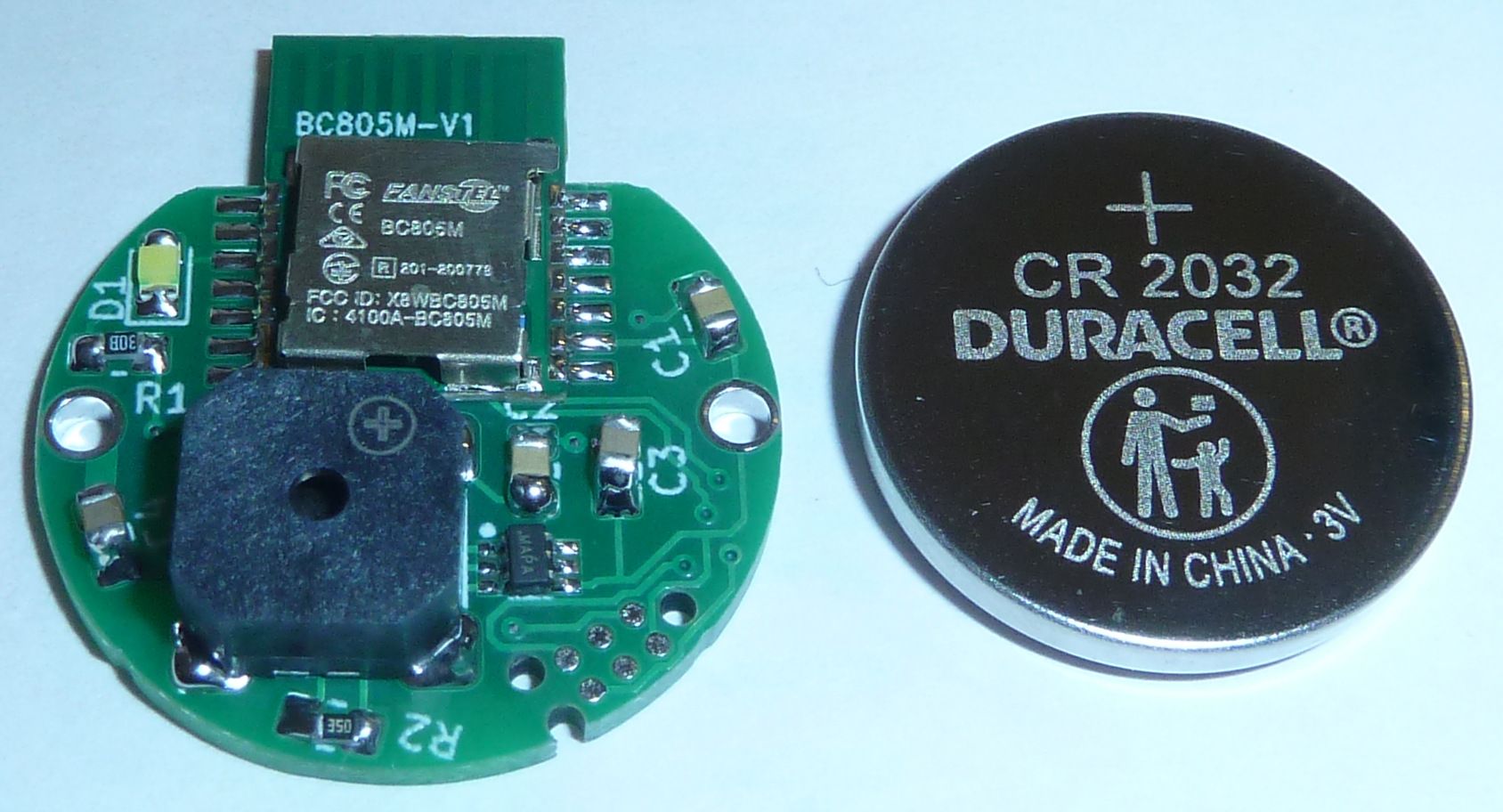
and I have a lot of alternate designs in the pipeline that I'll want to compare against it before picking a winner. Because of the buzzer dynamics, I have to actually build them in order to do a proper job of comparing them. For instance, the buzzer on this prototype is rated at 100dB at 10cm, but, as I've learned, that really only means 80dB at 1 meter if powered at 5v. But what is the SPL if powered at 3v or even 2v? Those are in the acceptable voltage range, but the datasheet doesn't say, so I have to buy buzzers and try them out in order to find out that kind of info. And it's not as straightforward as you might think, because the resonate frequency seems to change depending on the voltage. So, I have to discover that as well in order to do a proper apples-to-apples comparison.Further complicating matters is: how much current can a coincell really be counted on to deliver, especially as it ages and as its voltage drops. It turns out that answer isn't straightforward either, because it depends on how long you draw it for, and then there's a recovery period after which you can draw more current than if you don't wait for a recovery period. And how long do you need to wait, and so forth. Try figuring that out from a datasheet. That type of essential info just isn't there, and yet I need to know it if I'm going to compare the design in the photo against another design which might use, say, a CR2477 or a CR2450 or a CR123A, etc. Probably somewhere someone has built a coincell simulator to answer these types of questions. I presume that Durael or Energizer have the info but decided not to include it in their datasheets, maybe for marketing reasons.
So, to cut through all that, I'm taking the empirical route of build-and-test for a number of different design concepts, and I'll use the results to zero-in more quickly on the winner.
-
@Larson Thanks for your post. With parts getting ever more tiny, I think that would be a nice resource to leverage.
I'm presently learning more about buzzers than I ever wanted to know, but I'm having to discover the critical knowledge by experiment because the datasheets don't really adequately characterize them. In the end I think it's going to be a tradeoff between form factor, sound level, battery life, and the number of components needed to assemble the objective, as well as ease of assembly. My first design was this:
and I have a lot of alternate designs in the pipeline that I'll want to compare against it before picking a winner. Because of the buzzer dynamics, I have to actually build them in order to do a proper job of comparing them. For instance, the buzzer on this prototype is rated at 100dB at 10cm, but, as I've learned, that really only means 80dB at 1 meter if powered at 5v. But what is the SPL if powered at 3v or even 2v? Those are in the acceptable voltage range, but the datasheet doesn't say, so I have to buy buzzers and try them out in order to find out that kind of info. And it's not as straightforward as you might think, because the resonate frequency seems to change depending on the voltage. So, I have to discover that as well in order to do a proper apples-to-apples comparison.Further complicating matters is: how much current can a coincell really be counted on to deliver, especially as it ages and as its voltage drops. It turns out that answer isn't straightforward either, because it depends on how long you draw it for, and then there's a recovery period after which you can draw more current than if you don't wait for a recovery period. And how long do you need to wait, and so forth. Try figuring that out from a datasheet. That type of essential info just isn't there, and yet I need to know it if I'm going to compare the design in the photo against another design which might use, say, a CR2477 or a CR2450 or a CR123A, etc. Probably somewhere someone has built a coincell simulator to answer these types of questions. I presume that Durael or Energizer have the info but decided not to include it in their datasheets, maybe for marketing reasons.
So, to cut through all that, I'm taking the empirical route of build-and-test for a number of different design concepts, and I'll use the results to zero-in more quickly on the winner.
@NeverDie said in Most reliable "best" radio:
because the resonate frequency seems to change
Ahhh, I have something to offer. I remember way back when playing with piezo buzzers (something that is part of my mole project and in use today unfortunately) I remember incrementally changing the PWM frequency and duty cycle in the loop. I may be off base because I really don't understand what you are doing. But I remember that there is a sweet spot (resonant frequency, perhaps) where the sound would just pop. I've seen this in vocal quartets too (we are talking humans) when they hit some vibe some kind of God's amplifier gets invoked. It is really cool unless one has hyperaccousis, as I do. So I run an hide, but marvel at the science.
@NeverDie said in Most reliable "best" radio:
compare the design in the photo against another design which might use, say, a CR2477 or a CR2450 or a CR123A, etc. Probably somewhere someone has built a coincell simulator to answer these types of questions.
During dev, I try to overpower with big batteries, or lines to sort it all out before playing with the smaller cells. Understand the demands first, then find the cell that can deliver. The LIR2450 seemed to deliver a good punch of curent that can carry radio transmission peaks of a ESP8266, 400uF caps helped. Nice thing is that you can control the timing of the peak audio with any other peak load... like a radio or something and prevent an overload.
-
@NeverDie said in Most reliable "best" radio:
because the resonate frequency seems to change
Ahhh, I have something to offer. I remember way back when playing with piezo buzzers (something that is part of my mole project and in use today unfortunately) I remember incrementally changing the PWM frequency and duty cycle in the loop. I may be off base because I really don't understand what you are doing. But I remember that there is a sweet spot (resonant frequency, perhaps) where the sound would just pop. I've seen this in vocal quartets too (we are talking humans) when they hit some vibe some kind of God's amplifier gets invoked. It is really cool unless one has hyperaccousis, as I do. So I run an hide, but marvel at the science.
@NeverDie said in Most reliable "best" radio:
compare the design in the photo against another design which might use, say, a CR2477 or a CR2450 or a CR123A, etc. Probably somewhere someone has built a coincell simulator to answer these types of questions.
During dev, I try to overpower with big batteries, or lines to sort it all out before playing with the smaller cells. Understand the demands first, then find the cell that can deliver. The LIR2450 seemed to deliver a good punch of curent that can carry radio transmission peaks of a ESP8266, 400uF caps helped. Nice thing is that you can control the timing of the peak audio with any other peak load... like a radio or something and prevent an overload.
@Larson said in Most reliable "best" radio:
But I remember that there is a sweet spot (resonant frequency, perhaps) where the sound would just pop.
Yup, I've noticed the same, if by "pop" you mean becomes noticeably louder. It's not free though, as the current consumption also hits a peak at that frequency, which is yet another way to identify where the "pop" happens. But, anyway, yes, I agree, that is the magic sweet spot, and it's absolutely worth the extra current.
-
I ran into a "gotcha" with the larger piezo buzzer. It turns out that they have high enough inherent capacitance that you need either a resistor or something else to "drain" them during the off-phase of a square wave. Otherwise, the sound is minuscule. According to my Fluke multimeter, the large piezo's have only about 24nF of capacitance. I haven't yet checked with an LCR meter to confirm.
It turns out you can use an inductor instead of a resistor and setup a resonant circuit, which is more energy efficient than just using a resistor. So, I may try that, even though it's a more complex circuit to construct, because this way it will also increase the voltage (and hence volume) of the buzzer:

https://www.digikey.com/en/articles/design-techniques-to-increase-a-piezo-transducer-buzzer-audio-outputWhat's also interesting is that for buzzer's with a feedback terminal, you can use a simple circuit to automagically drive them at their resonate frequency:
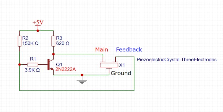
https://www.hackster.io/taunoerik/self-drive-piezo-buzzer-e9786f
Evidently this also serves the purpose of "draining" the buzzer without using a resistor directly across Main and Ground.Well, by trial and error, I've determined that it takes about a 100 ohm resistor to adequately "drain" the buzzer during the low phase of a square wave. Assuming 3V, that means 300ma wasted current during the high phase. On it's face, that seems excessive.
The small buzzers seem to neither need nor benefit from these drain resistors. I guess their inherent capacitance is simply too low to matter.
[Reporting back: I tried out the self driving buzzer circuit, and 1. it works at higher voltages of around 9-10v, and 2. even then it isn't as loud as a proper square wave at 3v. So... I'm nixing that idea. Besides, it's rather fiddly as to getting the component values just right in order to work, and who knows how much variation there might be in the manufactured piezo buzzers.]
-
Fun to see what hobbyists can achieve when they stick to it long enough:
https://www.youtube.com/watch?v=SH3lR2GLgT0 -
Fun to see what hobbyists can achieve when they stick to it long enough:
https://www.youtube.com/watch?v=SH3lR2GLgT0@NeverDie Yep, that rocket stuff, and that dedication-to-task stuff, is pretty cool. Thanks for sharing - very inspirational.
At a more modest level ... I received the Atmega 328P programming harness/clamp you recommended long ago. Nice. And your barebones board loaded with my RFM69HCW jig are working nicely. Also received: a bunch of your suggested radios and the carrying boards. Time, I need time. Can't thank you and @alphaHotel enough for the encouragement. I look forward to reporting if only to chronical for my own record and possible use for others.
I hope it doesn't take me 7 years, but it may. Now all I need is a bunch of 48 hour days.
-
What I've learned lately about buzzers, through experimentation, is that to get maximum loudness I need to drive a buzzer within about plus-or-minus 5Hz of its optimum resonance frequency. More than that and the loudness drops off precipitously. Unfortunately, manufacturing variance is probably more than plus-or-minus 5Hz, so that's a potential problem. The voltage supplied on the feedback pin of a piezo is only around 50mv, which is too low for an for an MCU to measure accurately without some kind of extra circuitry to help. It would be nice if the system could self-calibrate the driving frequency to match the inherent resonance frequency of the buzzer.
Meanwhile, I'm switching over to an H-bridge for driving buzzers, because an H-bridge not only efficiently drains the charge that builds up on the piezo buzzer but it also effectively doubles the peak-to-peak voltage seen by the buzzer. At these low voltages, more apparent voltage means more loudness.
When I started this project, I really didn't expect that the buzzer part of it would turn-out to require as much attention as it has! Sure, getting some amount of loudness is not a problem, but really maximizing loudness at these low voltages, while maintaining a tiny footprint and ease-of-assembly, isn't as easy as you'd think a priori.
@NeverDie said in Most reliable "best" radio:
It would be nice if the system could self-calibrate the driving frequency to match the inherent resonance frequency of the buzzer.
Perhaps an initialization User Interface selection? If the big picture is arranged and the region is only 5 Hz, then maybe a centeral default with an user option would be acceptable. Start slow, then rise in 0.25 Hz increments? If the user doesn't repond, then the default is mid-range. As in life, you can only help people so far. I think my mother tried to tell me that once.
Caveat User (Emptor).
-
@NeverDie said in Most reliable "best" radio:
It would be nice if the system could self-calibrate the driving frequency to match the inherent resonance frequency of the buzzer.
Perhaps an initialization User Interface selection? If the big picture is arranged and the region is only 5 Hz, then maybe a centeral default with an user option would be acceptable. Start slow, then rise in 0.25 Hz increments? If the user doesn't repond, then the default is mid-range. As in life, you can only help people so far. I think my mother tried to tell me that once.
Caveat User (Emptor).
@Larson said in Most reliable "best" radio:
@NeverDie said in Most reliable "best" radio:
It would be nice if the system could self-calibrate the driving frequency to match the inherent resonance frequency of the buzzer.
Perhaps an initialization User Interface selection? If the big picture is arranged and the region is only 5 Hz, then maybe a centeral default with an user option would be acceptable. Start slow, then rise in 0.25 Hz increments? If the user doesn't repond, then the default is mid-range. As in life, you can only help people so far. I think my mother tried to tell me that once.
Caveat User (Emptor).
You mean make it user selectable?
I'm toying with the idea of an initial calibration using equipment not on the PCB. That's how I arrived at the optimal frequency on my prototype. However, it's unpleasant listening to the frequency sweeps. Even my wife complained about it, and she was in a different room entirely. The only upside is that it's sure to work.
I found a good size for a shell, using a Govee temperature-humidity sensor:

It runs on a CR2477, so it has plenty of depth to it. Nobody seems to shell the shells though, and it would be a shame to canibalize their sensor just for the shell alone. I guess I'll have to 3D print something.... -
@Larson said in Most reliable "best" radio:
@NeverDie said in Most reliable "best" radio:
It would be nice if the system could self-calibrate the driving frequency to match the inherent resonance frequency of the buzzer.
Perhaps an initialization User Interface selection? If the big picture is arranged and the region is only 5 Hz, then maybe a centeral default with an user option would be acceptable. Start slow, then rise in 0.25 Hz increments? If the user doesn't repond, then the default is mid-range. As in life, you can only help people so far. I think my mother tried to tell me that once.
Caveat User (Emptor).
You mean make it user selectable?
I'm toying with the idea of an initial calibration using equipment not on the PCB. That's how I arrived at the optimal frequency on my prototype. However, it's unpleasant listening to the frequency sweeps. Even my wife complained about it, and she was in a different room entirely. The only upside is that it's sure to work.
I found a good size for a shell, using a Govee temperature-humidity sensor:
It runs on a CR2477, so it has plenty of depth to it. Nobody seems to shell the shells though, and it would be a shame to canibalize their sensor just for the shell alone. I guess I'll have to 3D print something....@NeverDie said in Most reliable "best" radio:
The only upside is that it's sure to work.
Very, very funny. Fell off my chair, funny. I had a similar experience with testing buzzers only I failed to recognize the upside/benefit. I ended up putting a switch on the speaker effect to maintain domestic tranquility.
Yes, frequency user selection was my thought. It sounded like the mV range detection/optimization was too complicated. If the design gets close enough to the expected range, then punt to the user for fine tuning.
Shells: Unless a resonant cavity is important, how about a simple tic-tac container with a pre-drilled speaker hole and some hot glue? Maybe a pezz container, if they make those any more? Even a Gatorade bottle cap filled with epoxy might work (use cellophane to cover/embed the mechanical parts of the speaker.) Failure has taught me many things, and this is one of them.
-
Good suggestion on using a tic-tac container. It never would have dawned on me. Too bad I'm on a Keto diet, but I guess I could give the tic-tacs to my son, who doesn't need to diet.
I may have spoke too soon that the nRF52 isn't sensitive enough to read the feedback voltage precisely enough. It turns out to have a 0.6v internal voltage reference, and it has a 12-bit ADC, so in theory it could measure in increments of as little as 0.6v/4096=0.146millivolts. Is that good enough? I really don't know, but I'm going to give it a try. The closer the piezo gets to resonance, the more the feedback voltage should shoot up. I'd be counting on it shooting up by a lot when it hits resonance. So, I just now uploaded the files to a fab for a PCB which can do those measurements, and hopefully I'll receive it in about a week. :-)
-
Check out the Hammond 1551V1gY (vented) or 1151SNAP1GY (unvented).
They look like they are about the same size. I've been using the vented ones for temp/humidity sensors. Not as ugly as most project boxes.@nagelc said in Most reliable "best" radio:
Check out the Hammond 1551V1gY (vented) or 1151SNAP1GY (unvented).
They look like they are about the same size. I've been using the vented ones for temp/humidity sensors. Not as ugly as most project boxes.Good find! I like the vented ones, as it look like they would let out a lot of sound.
-
Check out the Hammond 1551V1gY (vented) or 1151SNAP1GY (unvented).
They look like they are about the same size. I've been using the vented ones for temp/humidity sensors. Not as ugly as most project boxes.@nagelc said in Most reliable "best" radio:
Check out the Hammond 1551V1gY (vented) or 1151SNAP1GY (unvented).
They look like they are about the same size. I've been using the vented ones for temp/humidity sensors. Not as ugly as most project boxes.@nagelc I ordered the white version of the vented model you referred to so that I can give it an up-close looky-loo. I also found an interesting "similar but different" vented enclosure from New Age Enclosures, though at twice the price, which I also ordered for comparison:

https://www.mouser.com/ProductDetail/789-P1A-151510
With benefit of hindsight, maybe I should have started to look at possible enclosures from the get-go, because, depending on what's available, that may very well determine what form factors are even worth considering. :face_palm: i.e. the project will end-up needing to fit the enclosure, probably not the other way around. -
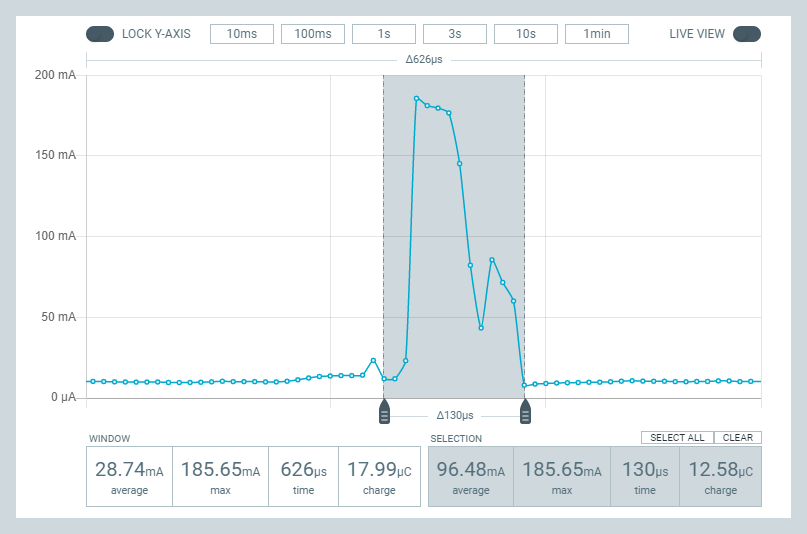
I think I may now finally understand the purpose of the optional S0, LENGTH, and S1 fields in the nRF52 packet frame. The datasheet gives very little insight into them, so I had previously disabled those fields just to avoid the topic altogether because it seemed so obscure. However, in trying to figure out how to send/receive packets between an nRF52 and an old-style nRF24L01+, the puzzle finally makes sense: they are there to either 1. provide a means of compatability with the nRF24L01's Enhanced Shockburst, which puts a 9-bit field in the middle of the frame:
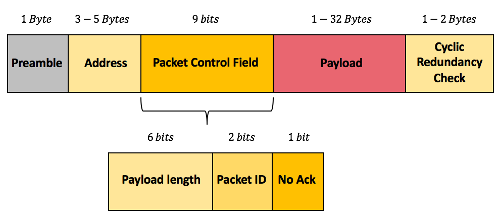
or 2. allows you to roll-your-own super Enhanced Shockburst with extra bits (in which case standard nRF24L01P ESB compatibility goes out the window). Well, for a host of reasons, I think nRF24L01p compatability is worth enduring an extra 9 bits of airtime, so I'll go that route and configure the nRF52 accordingly now that I've inferred what those fields are meant for. :face_with_cowboy_hat: -
I like your ideas. Is there a circuit for common mode rejection? It would be worth exploring. And using a test port for different pull-up resistors, better yet a variable resistor, would allow for testing.
-
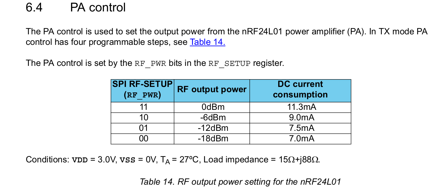
Reporting back on the E01-2G4M27D radio's that I had referenced earlier. For those who don't remember, these are nRF24L01P radios that have been upgraded to use a 27dBa PA and, allegedly, other higher quality components (https://www.ebyte.com/en/product-view-news.aspx?id=450). 27dBa = 0.5 watt. For comparison, the maximum Tx power of a plain nRF24L01 is just 0dB. I had occasion to try them out today, and they appear to perform extremely well, even at 2mbps while transmitting over the worst-case transmission path in my house that I've been using to test all the radios on.
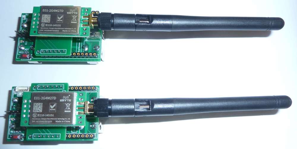
I'd venture to say that in terms of reliably getting a packet through to its destination, they outperform all other enhanced nRF24L01P's that I've ever tried previously. If you opt to try them on the test platform, as I have done, I recommend you upgrade your BoB capacitor to 100uF or 200uF, because 10uF doesn't seem to be enough when transmitting from somewhat weak batteries. Nonetheless , 10uF is sufficient if powering it from a really stiff power source. Ironically, they vastly outperform the 2.4Ghz LoRa radios that got me started on this whole mini-blog in the first place.Looks as though you can buy them on sale at $4.59 each: https://www.aliexpress.com/item/2255800350626109.html?gatewayAdapt=4itemAdapt
No, they don't come with the antennas. You'll have to source those separately.I'd say the main downside to these modules is that there does not appear to be any way to dial-down the transmission power, so that you only use as much power as you really need to fit your circumstances. There's no reason that such a module couldn't be designed and built (just as the RFM69HW allows), but, AFAIK, there aren't any on the market like that for the nRF24L01P. It's such an obvious enhancement that I'm surprised none of the vendors have offered it, even if it requires extra pins. Maybe someone reading this knows of one? If so, please post.
-
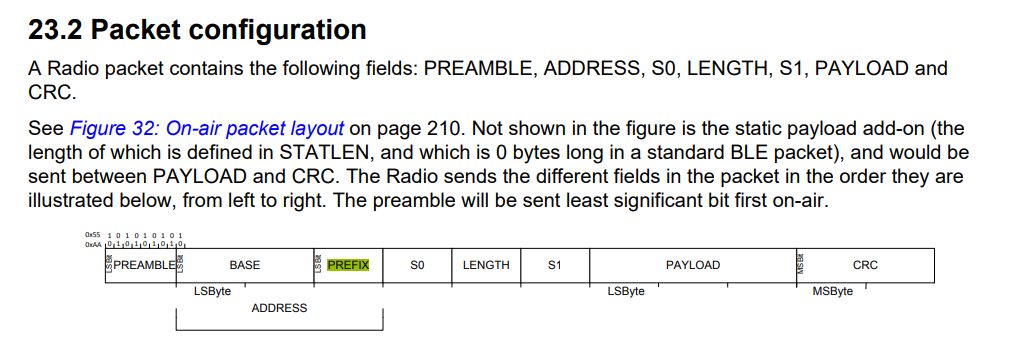
:face_palm: Doh! It just occured to me that rather than being a fixed output power, maybe these modules actually do have adjustable gain via adjusting the power output of the nRF24L01P:
That would perhaps mean that you could adjust the power output to be 27dB minus 18dB = 9dB? i.e. they effectively offer a gain of 27dB to whatever output power your radio chip already has? Is that how PA's work? Or, instead, would it just be blasting out mostly noise at 27dB if I were to set the nRF24L01P's output power to -18dBm? I'm guessing the former and not the latter, but unfortunately I don't have any radiated RF power measuring equipment that might tell me the answer. Anyone know? Perhaps measuring the current consumed during transmission would tell the tale, as one could infer the output power from that. Hmmmm...... Worth a try. Might be able to approximate the answer from that. If it turns out that they are adjustable in this manner, then I would think they are pretty awesome as a default "go to" module for just about anything. i.e. you'd have good communication even on the low-end of 9dB, but you would also have plenty of headroom to notch it up to a higher output power if it were truly necessary to cover whatever contingency you might run into, provided it remains within the legal limits of whatever your jurisdiction is.
I once tried (and reported on) a 4watt 2.4Ghz amplifier that you can buy on amazon, and it had a "sweet spot" for input power that it could amplify from, but below that sweet spot it didn't do much good at all. Perhaps that's a more accurate model of how this works in real life?
Looking at the manual, it does say the output power is multi-level software adjustable, so there's hope. https://www.ebyte.com/en/downpdf.aspx?id=450 I don't see that it offers any hints beyond that though.
-
Well, attempting to answer my own question above, here is the power profile of the E01-SG4M27D when the nRF24L01P is set to 0db (plus whatever power the PA on module boosts that to):
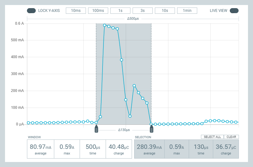
Here it is when the nRF24L01P is set to -18dBm ( (plus whatever power the PA on module boosts that to):
So, it looks as though the latter is the current is roughly 1/3 of the former, and since the voltage is the same, that would imply that the power is about 1/3 also. However, if my earlier theory was right, then the second chart should be showing a maximum of about 7.4mw, as compared to the theoretical 500mw of the first chart.
So, really, neither chart makes much sense. 3.3v x 580ma = 1.9 watts and 3.3v x 180ma = 0.594 watts. Well, I guess that's wrong if the radio module converts the 3.3v to a lower voltage for running the radio at via an LDO, which means it disappates the difference as heat. Still, the ratio between high and low Tx power is something like 3 to 1, whereas in theory it should be more like 67 to 1. So, I really don't know what to make of all that, other than the PA doesn't have much dynamic range to it. Does that extra power at the low end translate into proportioinately more radiated RF? I have no way of knowing, as this is the limit of what I can test with the equipmet that I have. I'd need something which can measure actual radiated RF.
This guy demonstrates how that might be done:
https://www.youtube.com/watch?v=FVaiWzJSvNUIn a nutshell, it would require both the power meter and, in this intance, an attenuator to go along with it.
I suppose an alternate, non-elegant way to solve the problem would be to have an array of different nRF24L01 modules, each optimized for a different power level. Then, by selecting the right CE pin, you could switch among them for the desired power level for a transmission. Not completely outlandish if size doesn't matter so much, because nRF24L01P modules, in whatever flavor, are generally fairly cheap--perhaps cheaper than buying the $80+ worth equipment needed to measure RF power that would probably be only one-time use. So, for a gateway, that might be a possibility. For a sensor node, probably not.
-
I think I may now finally understand the purpose of the optional S0, LENGTH, and S1 fields in the nRF52 packet frame. The datasheet gives very little insight into them, so I had previously disabled those fields just to avoid the topic altogether because it seemed so obscure. However, in trying to figure out how to send/receive packets between an nRF52 and an old-style nRF24L01+, the puzzle finally makes sense: they are there to either 1. provide a means of compatability with the nRF24L01's Enhanced Shockburst, which puts a 9-bit field in the middle of the frame:
or 2. allows you to roll-your-own super Enhanced Shockburst with extra bits (in which case standard nRF24L01P ESB compatibility goes out the window). Well, for a host of reasons, I think nRF24L01p compatability is worth enduring an extra 9 bits of airtime, so I'll go that route and configure the nRF52 accordingly now that I've inferred what those fields are meant for. :face_with_cowboy_hat:@NeverDie said in Most reliable "best" radio:
I think I may now finally understand the purpose of the optional S0, LENGTH, and S1 fields in the nRF52 packet frame. The datasheet gives very little insight into them, so I had previously disabled those fields just to avoid the topic altogether because it seemed so obscure. However, in trying to figure out how to send/receive packets between an nRF52 and an old-style nRF24L01+, the puzzle finally makes sense: they are there to either 1. provide a means of compatability with the nRF24L01's Enhanced Shockburst, which puts a 9-bit field in the middle of the frame:
or 2. allows you to roll-your-own super Enhanced Shockburst with extra bits (in which case standard nRF24L01P ESB compatibility goes out the window). Well, for a host of reasons, I think nRF24L01p compatability is worth enduring an extra 9 bits of airtime, so I'll go that route and configure the nRF52 accordingly now that I've inferred what those fields are meant for. :face_with_cowboy_hat:It worked! :smile: :smiley: :slightly_smiling_face: Well, sort-of. I have it working using the five byte address 0xE7E7E7E7E7, which dodges the question of how the address bytes are ordered over the air in one scheme versus the other. That's the next puzzle to solve. You might think this would be easy to solve, as I did, but so far not.
Here's part of what's weird (this is taken from the nRF52 datasheet):
Can you see the disconnect? On the nRF52 the LENGTH field comes in the middle of the 9 bits, whereas on the nRF24L01 ESB it comes at the front of the 9 bits.
Also, I haven't been able to get any non-repeating address to work yet. e.g. x0101010101 works, and so does 0xE7E7E7E7E7, but that's a rather limiting type of address to rely upon, though I suppose I could live with it if I had to. Go figure.