Most reliable "best" radio


  • Hero Member

    @Larson said in Most reliable "best" radio:

    @NeverDie said in Most reliable "best" radio:

    By the way, when I checked the voltage remaining on the coincell taken from this keyfinder receive, it measures about 3mv. So, it got drained practically all the way to zero.

    I've seen this when playing with 328's and 8266's. When voltages drop to the min threshold, the devices fail into a funky state drawing big current. For that reason, my current designs give out a yelp at a moderately low voltage, if there is a radio attached. Then go into deep sleep hoping that a rescue arrives. Deep discharges are really problematic for rechargeable liOn batteries. The advice is to abandon the battery because of potential changes to chemistry and the risk of fire on recharge.

    What kind of device/component do you use to make the yelp sound? I've looked for tiny piezo's that could maybe do this, but they all seem to be different degrees of large. I know it should be possible to be tiny, becaue, for example, a digital wristwatch is able to make audible beeps. On the other hand, after looking at some teardowns, I guess digital watches uses piezo disks that are at least 1/2" in diameter. Hmmmm.... Is that really as small as it gets? Anyone here know? What about hearing aids? Surely they have something smaller. The smallest thing I've found so far has been this: https://owolff.com/page140.aspx?recordid140=534&output=pdf&delay=3000&margin=1cm which is 5mm in diameter. So, I guess forget mounting anything directly to the PCB board: wired discs are the way it's done apparently and then just tuck it somewhere inside the project enclosure.


  • @NeverDie said in Most reliable "best" radio:

    What kind of device/component do you use to make the yelp sound?

    My present "Yelp" design comes from a Thingspeak script that sends an email. Yelp may have been the wrong word, but I was thinking of smoke detectors that beep to say, "I'm dying, replace my battery". Previously, I built a WiFi mouse trap that sent email/text/phonecall via SMTP2GO if the trap was tripped (mouse, or no mouse). That was fun! That code could easily be modified to trigger on a voltage threshold, or any other variable.
    8eb77c79-9a5e-47aa-9d04-64e6c23d01e5-image.png image url)


  • Hero Member

    @Larson That's a nice, clean looking, elegant design. If you have any idea on how to kill skunks, let me know. They are destroying my lawn. Live capture doesn't seem practical for skunks, for obvious reasons. I've seen one youtube that demonstrates a deadfall device--and proves it works--but it's the only example I've managed to find. There do exist professional services, but they charge a couple hundred bucks per animal removed, but after removal they can't legally release them (because they are officially pests), so the pro's just end up killing them anyway.


  • @NeverDie For skunks, and racoons I use an electric fence. I string a wire around the lawns & ferns about 6" up from grade using non-conducting stakes. I think it works and is non-lethal. The e-fence was the smallest Coastal Farm offers. Our cat has 'figured' it out and knows to stay away.

    In the spirit of radio electronics, I did build a system for mole elimination. It was complicated. I use a vibration detector/WiFi (ESPNOW) that sends notice to a piezo beeper inside the house. The detector is planted in the last active mole pile. If I hear the beeper I jump to action to hit a button (Transmit/Recieve pair) to ignite an electronic firecracker that would be burried in the last visited mole pile. I could have automated that button-pushing task, but the extra human control made it safer and more entertaining. The firecracker is be fitted with a nicrome wire fork, inplace of the normal fuse. The firecrackers I prepared were painted in some waterproof paint to keep them from degrading in the moist soil. An 18V Ryobi tool battery is used for the power source in the relay circuit because that gives enough juice to burn the nicrome wire. I tested it but have yet to deploy it. Here is the circuit for the igniter.![alt text](ad273793-db9e-4419-bcaf-1fcf9a914265-20200721_194254.jpg image url)


  • Hero Member

    @Larson Will a firecracker actually kill a mole? This guy shows off his simple contraption that uses 500v to instantly kill rodents:
    RID-O-RAT Homemade Electronic Pest Control Device – 12:16
    — electronicsNmore

    The key seems to be charging high voltage capacitors, so that enough current is released at 500v when triggered. I know: dangerous as hell, but maybe this is where your wireless human-in-the-loop firing trigger could come into play so that it doesn't kill anything that it's not supposed to.

    He says it's highly effective.

    I don't know whether something like that would work for moles or not. I guess it depends on whether they ever leave their holes to look for food or whether they stay underground all the time.

    I wouldn't feel comfortable walking up to something charged to 500v, but maybe that's where radio electronics could completely disarm it down to zero volts when commanded before you even think of touching it. His is more basic and doesn't have that added feature. I would want redundant everything on the safety features so that there's no chance of it going wrong.

    As for charging it up, I think one of these would work for fairly cheap:
    https://www.amazon.com/gp/product/B07JG4K6S6/ref=ppx_yo_dt_b_search_asin_title?ie=UTF8&psc=1
    as long as you terminate the charge when it gets to 500v and not let it continue on to 15,000 volts, which would destroy your charge capacitor. Since it comes in a pack of two, maybe the other one could be used to energize an electric fence? I know nothing about electric fences or what voltage they use, but I would hazard a guess that the circuitry is similar (flyback transformer design), and then all you would need is the right kind of wire and some insulated stakes.

    An electric fence is an interesting idea, provided it doesn't ignite dead leaves and create a fire. Not sure whether or not that's even a risk. I presume that professional electric fences wouldn't do that.


  • @Larson Do you have any links to this please? I found next doors 2 new cats killing 2 young birds they had paicked out of the tree and onto my lawn. The owners are un-cooperative on the issue and the cats have been using my garden as their own litter tray..... Garlic, chilli powder and vinegar have had no effect so I need to up the game!


  • Hero Member

    @skywatch We had a neighbor with a cat like that once. Same liter box behavior as what you describe. I was sooooo glad when they finally moved to somewhere far away.


  • @NeverDie said in Most reliable "best" radio:

    Will a firecracker actually kill a mole?

    I'm not sure. But the MoleCat100 uses the blast from a 22 blank, and that has to be close to the concussive force of a firecracker. Being under the dirt by about 4" has to also help in rendering an effective shock wave since dirt is far less compressible than air.

    @NeverDie said in Most reliable "best" radio:

    The key seems to be charging high voltage capacitors, so that enough current is released at 500v when triggered.

    Smoking Cool, and yea, probably dangerous. I was playing with flash bulb circuits from disposable cameras as a potential igniter. I accidently shorted a loaded circuit, and the thing burned a hole in my screw driver. Stunned and temporarily blinded, I put it away immediately and haven't gone back since. I don't think the 500 V device would work on moles; they do their foraging in their tunnels. Probably grubs and worms. Maybe they come out at night?

    MouseTrapMonday has probably featured this 500 V device. He has quite a collection.

    The Comidox 15KV looks like fun, and again dangerous. Glad to see that the thing comes disassembled. Assembly provides some knowledge requirement at least.

    My electric fence is this one. It seems to have internal circuitry that limits grounding problems. The thing sends pulses at about 1Hz. Using a blade of grass, or green straw one can feel the pulses. I've had branches fall on the fence and pin it to the ground without resulting in problems so far. It would be fun to do a tear-down to learn how they work... but I've got these radios to play with.


  • @skywatch said in Most reliable "best" radio:

    Do you have any links to this please?

    Sure, Here it is on Amazon. I got mine at Coastal Farm and Ranch. While I'm now using it for skunks and racoons, I initially used it on the swim platform of my old wooden boat that was a party scene for sea otters. They can really stink up the boat after a winter.


  • Hero Member

    @Larson Since it's fed by AC from the wall, I'm guessing it's a relatively straight forward transformer based design rather than a flyback circuit, but I'm no expert in such things. I presume there's some kind of circuit in addition which renders it safe and non-lethal. Probably best to go with something known to work safely like that for an electric fence and not go the flyback transformer route, especially since the price is so low to begin with.


  • @NeverDie I wouldn't know as I haven't studied power supplies outside of the engineering fundaments, yet. There is a version of these fences that use car batteries & solar charging. So they probably use different transformers.

    I sure hope we didn't stink-up your thread with all this rodent-talk.


  • Hero Member

    @Larson said in Most reliable "best" radio:

    I sure hope we didn't stink-up your thread with all this rodent-talk

    No worries. I'm not a stickler for staying on topic. I always say go where the interest is.


  • Hero Member

    @Larson said in Most reliable "best" radio:

    MouseTrapMonday has probably featured this 500 V device. He has quite a collection.

    He's the one who demonstrated the dead fall skunk killer. He's also demoed some no-spray catch-and-release traps, but I don't see those as practical for anyone but the pro's. The way they work is interesting though: supposedly a skunk has to be able to raise its tail to spray, and the no-spray traps don't give them enough room to do that. The downside is that once you release a skunk from the no-kill trap, it can raise its tail and spray you, which is what happened to him in one of his videos.


  • @NeverDie Hilarious.

    Release problem: Nothing that a remote, a servo, a relay, and a radio couldn't solve. All of which would get sprayed anyway. Hmmm...


  • @Larson said in Most reliable "best" radio:

    Hilarious

    Uh... after finding and watching the dead fall video, I downgrade my "Hilarious" comment to "Interesting". Back to the joy of radios!


  • Hero Member

    @Larson said in Most reliable "best" radio:

    @Larson said in Most reliable "best" radio:

    Hilarious

    Uh... after finding and watching the dead fall video, I downgrade my "Hilarious" comment to "Interesting". Back to the joy of radios!

    I know what you mean. Not sure why, but even if the crush physics are equivalent, somehow his design does seem more disturbing than having a giant falling bolder do the dirty work. On the other hand, at some level it's no worse than road kill, which happens all the time, and most people seem relatively dismissive about that.

    In any case, thanks for your post and info regarding the electric fence.


  • Hero Member

    As a first pass I tried running the RadiolLlb on these two 20dBm nRF24L01's with the default settings:
    2xnRF24L01_high_power.jpg
    and although they work fine at closer ranges, they delivered zero packets (i.e. total fail) along my worst-case transmission path. Make of that what you will. I'll see if I can possibly tweak some settings for a better result and then re-test, but those are the early results. I thought them worth testing because many people here like the nRF24L01 radios and because those radios do have good support for over-the-air updates on the atmega328p.

    To be fair, there do exist some nRF24L01 modules on Aliexpress with even higher transmission power, so maybe a pair of those would cut the mustard.

    I purchased them on amazon, mainly because I could receive them a lot faster than ordering something from China: https://www.amazon.com/dp/B07QC1SXJ8?psc=1&ref=ppx_yo2ov_dt_b_product_details

    [Edit: same results even if I reduce the datarate to 250kbps. ]

    Well, too bad. They do work for short range. Although this isn't rigorous testing by any means, I'm concluding that long-range for the nRF24L01, or other impairments, is essentially out of consideration Its niche is short-range, and for non-amplified versions preferably line-of-sight short-range. Sorry if that seems harsh, but for a comparison of different radio modules, somebody has to call it--and that's how I'm calling it. If somebody has a better nRF24L01 module that they feel would test better, please make a post and let us know what it is.


  • Hero Member

    Surprise! I'm getting it the nRF24L01 modules to send and receive, even along my worst-case transmission path, though for some reason ack's aren't being received along that worst-case path. Not sure why there would be an asymetry like that. Apparently the RadioLib library didn't default to full transmission power, because when I set transmit power to 0dB (which gets amplified by the PA), I'm now getting great radio communication. And this is the 2.4Ghz band, no less. Who would have thought? I'm flabbergasted. If anyone wants to replicate, I've posted my modified RadioLib sketches to source-code tab of the openhardware.io project for the nRF24L01 adapter.

    Even if I increase the datarate to 1mbps, the majority of the packets are still getting through. This may turn out to be a closer horserace than I had originally thought: it may yet require some careful measruements to separate out the winner.

    [Edit: As a result, I just now ordered some of these E01-2G4M27D: https://www.aliexpress.com/item/3256801616913450.html?spm=a2g0o.order_list.0.0.24f21802jP9dtI
    presently on sale for $4.34 each with free shipping, which allegedly contain TCXO's and, hopefully, should be a further step-up in performance. In fact, these may be the top-end of what's currently available on the market in the nRF24L01 series.

    Now the long wait for them to arrive....]


  • @NeverDie said in Most reliable "best" radio:

    If anyone wants to replicate, I've posted my modified RadioLib sketches to source-code tab of the openhardware.io project for the nRF24L01 adapter.

    That is my aim (to replicate). I've got these radios on order, but from China.

    @NeverDie said in Most reliable "best" radio:

    Not sure why there would be an asymetry like that.

    I'm thinking... maybe because of the compounded probability of the second (ack) transmission? Maybe having a secondary transmision counter for the ack would help? I'll play with it if I'm not too late. As said, you move fast.


  • @NeverDie One other late thought is to have some standard of antennae selection. I was thinking to make the different radios comparable some limit would be needed, I was thinking I'd stick to the bare 1/4 WL wire. But, reality of antenna science is probably far more complex. Thoughts?


  • Hero Member

    @Larson said in Most reliable "best" radio:

    That is my aim (to replicate).

    Great! When you do, be aware that I found a bug in the RadioLib library wrt the nRF24L01, but it's easily patched: replace micros() with millis() in this section of their library code:

    int16_t nRF24::receive(uint8_t* data, size_t len) {
      // start reception
      int16_t state = startReceive();
      RADIOLIB_ASSERT(state);
    
      // wait for Rx_DataReady or timeout
      //uint32_t start = _mod->micros();
      uint32_t start; 
      start = millis();
      while(_mod->digitalRead(_mod->getIrq())) {
        _mod->yield();
    
        // check timeout: 15 retries * 4ms (max Tx time as per datasheet)
        //if(_mod->micros() - start >= 60000) {
        if((millis() - start) >= 60000) {
          standby();
          clearIRQ();
          return(RADIOLIB_ERR_RX_TIMEOUT);
        }
      }
    

    I commented out their erroneous code and put my corrected code beneath it. Doing this will allow the radio to listen in Rx mode for a minute before timing out. If you don't make the change, it will time out after 60ms, which I can't imagine is what they intended.

    Of course, you may choose to use/try a different nRF24L01 library entirely. There are plenty to chose from.


  • Hero Member

    @Larson said in Most reliable "best" radio:

    I'll play with it if I'm not too late

    I imagine you'll have plenty of time. I'll try again when the E01-2G4M27D's (see edited comment above) arrive, but unfortunately those may not arrive until the end of July according to aliexpress.


  • Hero Member

    @Larson said in Most reliable "best" radio:

    @NeverDie One other late thought is to have some standard of antennae selection. I was thinking to make the different radios comparable some limit would be needed, I was thinking I'd stick to the bare 1/4 WL wire. But, reality of antenna science is probably far more complex. Thoughts?

    You raise a good point. Not really sure. I'll have to marinate on that one. For better or worse, some modules more or less force the use of different antennas than just a wire-whip or spring, because they come equipped with SMA connectors or u.fl connectors or they have trace antennas. As near as I can tell, dipole antennas are generally the best overall, unless you're deliberately trying to do something directional. So, one could maybe argue that we should test with dipole antennas, although that's easier said than done because it's easier with some modules than others.

    I started this radio testing with the expectation that one radio, or at least one type of radio, would stand head-and-shoulders above the rest, regardless of antenna type. However, maybe that won't turn out to be the case, which will in itself be be an interesting result if that's how it plays out. For instance, by picking the E01-2G4M27D to test with, I'm certainly giving the nRF24L01 far more advantage than it ever would have if I were using just regular dirt cheap nRF24L01 modules without any PA or LNA. Those by themselves would have no chance of competing, except at very short range. However, for very short range applications, they may very well be winners because of their 2mbps data rate.


  • @NeverDie said in Most reliable "best" radio:

    Of course, you may choose to use/try a different nRF24L01 library entirely. There are plenty to chose from.

    As I say to my physician, dentist, and probably my mother: you lead, and I will follow. Your library is my library.


  • @NeverDie said in Most reliable "best" radio:

    I started this radio testing with the expectation that one radio, or at least one type of radio, would stand head-and-shoulders above the rest, regardless of antenna type.

    Yep. And that is why I was thrilled with your earlier conclusions about the SX1262. Andreas Spiess convinced me that maximizing design parameters depend on the needs. Bit rate, bandwidth, power demands, range, and other factors are all working against each other, or with each other. Wish I knew the fundamentals and that is my aim. It would be fun to stay with one radio and just change the parameters and antennae. That has probably been done in academic circles. Imagine what led to the progressive development of different radios. I'm sure it wasn't random. We are left to discover why.

    Back to school for me.


  • Hero Member

    It seems that I was able to get an improvemet from no ACKs to a majority of ACKs just by installing fresh batteries on the receiver. That was an improvement from 2.9v with the old batteries to 3.2v with the new fresh AA's. So... it makes me wonder whether there'd be even more improvement if it were running at the maximum allowed 3.6v. So, I tried powering it with an external power supply, but performance went down dramatically even at the 3.2v level. I guess probably from longer wires or maybe some other source of noise. Anyhow, just memorializing these findings here as a reminder in case it's worth exploring this topic further in the future.


  • @NeverDie Maybe just ripple on the DC? Did you scope it to see? Maybe try with 10n , 100n and 470uF caps across the DC power line? - Or if there is an onboard regulator on the RF module, then maybe that gets more noisey as the voltage drop across it increases?


  • @Larson Thanks- they are a LOT more expensive here, but cheaper versions are available - sorry for diverting the thread a little.


  • Hero Member

    @skywatch said in Most reliable "best" radio:

    @NeverDie Maybe just ripple on the DC? Did you scope it to see? Maybe try with 10n , 100n and 470uF caps across the DC power line? - Or if there is an onboard regulator on the RF module, then maybe that gets more noisey as the voltage drop across it increases?

    It does already have 100n (=0.1uF) across the DC power line, extremely near the inputs to the nRF24L01. I didn't check those other things though. However, given how widespread the use of the nRF24L01 is on this forum, if anyone happens to know whether powering it with voltage at the higher end of its range improves performance, please post. I think for the LoRa chips it doesn't matter, because they all down-convert anyway. Maybe the nRF24L01 does as well? I really hadn't expected the nRF24L01, boosted as it was with PA and LNA, to do as well as it did. So, there's that added layer of PA + LNA complexity that may have something to do with it, not just the nRF24L01 chip itself. If I was focused on just one particular chip or module, I could do those tests. But multiply that workload by six or so other radio modules, all with different idiosyncrasies, and I quickly run out of time. I may have bitten off more than I can chew. So, I just have to draw the line and either come back to it in the future or not, depending on how the global picture develops. But if someone already happens to know the answer, then hopefully they might make a posting.

    This guy just recently did a video on nRF24L01 problems:
    NRF24 Frustration - Radio module doesn't work? – 12:46
    — Electronoobs

    and the very first thing he talks about is long wires.


  • Hero Member

    @Larson said in Most reliable "best" radio:

    @NeverDie said in Most reliable "best" radio:

    I started this radio testing with the expectation that one radio, or at least one type of radio, would stand head-and-shoulders above the rest, regardless of antenna type.

    Yep. And that is why I was thrilled with your earlier conclusions about the SX1262. Andreas Spiess convinced me that maximizing design parameters depend on the needs. Bit rate, bandwidth, power demands, range, and other factors are all working against each other, or with each other. Wish I knew the fundamentals and that is my aim. It would be fun to stay with one radio and just change the parameters and antennae. That has probably been done in academic circles. Imagine what led to the progressive development of different radios. I'm sure it wasn't random. We are left to discover why.

    Back to school for me.

    I did that once with the RFM69, and the parameters on that radio are numerous and a real challenge to fully understand. The API of the newer LoRa radios is a lot simpler, which is fine by me.

    If it weren't for the 2mbps, or even 1mbps, capability of the nRF24L01 (and related nrf5x modules, of course), I would drop the nRF24L01 like a hot brick. But those high datarates, and especially mysensors support for OTA updates using it, offer a compelling advantage.

    So, now that there's a common test platform--one without long wires--we'll just see how it all develops.

    It would be fun to test the si4468, which looks very capable, but I think I'm already at the limit of what I can consider all at one time.


  • Hero Member

    @Larson Now that you have a PPK2, there's an easy way you can check for whether or not your plain, ordinary nRF24L01 chips are fake or not: looking at the Tx and Rx current draws and comparing them to the datasheet. For instance, on this particular nRF24L01 module:
    alt text

    Here is the Tx and Rx profile from running the RadioLib transmit script I posted in source code section:
    nrf24L01_tx_rx_currents.png

    The first plateau is the transmit current. The second plateau is the Rx current, where it's listening for an ACK. Well, as you can see, the Tx current is about 26-27ma and the Rx current is around 14-15ma. So, next, compare that to the specifications in the nRF24L01 datasheet:
    nrf24L01_datasheet_currents.JPG

    and you can see that the values don't match. Not even close! 26-27ma is way beyond the spec of 11.3ma for maximum current draw,and 14-15ma is above the max of 12.3ma for Rx. So, the chip on this module, even though it says, as you can clearly see in the photo itself, that it is NRF 24L01+, it's a total fake. No question about it. Not only that, but if you want to, you can identify exactly which fake chip that it is, by looking at the datasheets of known fakes and looking for a match.

    When in doubt you can also measure and compare sleep currents, which varies between the real and various fake chips. As you'd probably expect, Nordic has the lowest sleep current of any of them, at least as far as I'm aware.


  • Hero Member

    @Larson In this case, it's almost certainly the si24R1 chip, because if you look at the datasheet here: https://datasheet.lcsc.com/lcsc/1811142211_Nanjing-Zhongke-Microelectronics-Si24R1_C14436.pdf and zoom in on the electrical specification, you see that the specified currents are:
    si24R1_datasheet_currents.JPG

    which is a very close match.

    😄

    I've written about this before (here: https://forum.mysensors.org/topic/1664/which-are-the-best-nrf24l01-modules/285 , where it took me a lot of effort to finally figure all this out), but it's so buried at this point that I doubt anyone new to the game is even aware of it. So, I include it here, as bonus perk for anyone who happens to be reading this thread. Nice, ya?


  • Hero Member

    By the way, if I did end up using the nRF24L01 (or nRF5x series), I'd like to do what I outlined in the last post on that thread (https://forum.mysensors.org/topic/1664/which-are-the-best-nrf24l01-modules/309?_=1654977950928), which is to do channel hopping and time synchronization among motes. There are some interesting demos on distributed time synchronization which are pretty cool:
    Proportional Integral Clock Synchronization in Wireless Sensor Networks – 01:00
    — Kasım Sinan Yıldırım

    One simple (but maybe not the best technique) is to have each node transmit its local time in some kind of sequence, while the other nodes listen and take note. Then by averaging these local times over a few iterations, the group converges onto a single time. Pretty neat, huh? I would imagine that, more efficient and less complex, would be to have a powered wireless time server, and then everything syncs to that.


  • Hero Member

    And this youtube succinctly explains why it's worthwhile:
    Wheel of Blinking LEDs – Wireless Time Synchronization – 02:50
    — Analog Devices, Inc.

    TL;DR: much longer battery life, among other things.


  • @NeverDie You probably already considered this but using a co-ax cable for the power would offer some sheilding and also after watching the video you linked maybe some of those tiny ferrite beads on the data and power at the radio might be of help.

    I had to chuckle when the guy in the video showed how he connected an external antenna without first removing the link to the PCB one!

    If I can I will try one of the cdebyte modules on 3.6V and see if they are still good... Remind me in a week if I don't get it done!


  • Hero Member

    @skywatch said in Most reliable "best" radio:

    those tiny ferrite beads

    Have you tried it before? Exactly which tiny ferrite beads do you recommend? Mouser lists over 4,200 different ones.


  • Hero Member

    Well, the nRF24L01 datasheet says, "The nRF24L01 transmitter PLL operates in open loop when in TX
    mode. It is important to never keep the nRF24L01 in TX mode for more than 4ms at a time."

    Disappointing, but I believe I can work around that limitation.

    Why is there a limitation on Tx time but not Rx time? Is it a thermal issue of some kind?


  • @NeverDie said in Most reliable "best" radio:

    I've written about this before (here: https://forum.mysensors.org/topic/1664/which-are-the-best-nrf24l01-modules/285 , where it took me a lot of effort to finally figure all this out), but it's so buried at this point that I doubt anyone new to the game is even aware of it. So, I include it here, as bonus perk for anyone who happens to be reading this thread. Nice, ya?

    Yes, very nice. But how would you know where to look for the si24R1 chip amongst the others? I haven't read the other thread, just yet - it is the end of a very long sweaty fuse-setting day. Not only just a perk, your writing on these subjects is a library for others. Like today, I'm reading Nick Gammon's posts from 2012. They are there and very relevant still - I spend much of the day reading them. In 2032, should we get that far, folks will be upstudying your material.


  • Hero Member

    @Larson Somewhere I found a list of known clones. I linked to it in the original thread that I referenced above. si24R1 is China's clone of the nRF24L01. Ebyte even explicitly advertises it as a clone on their website and in their aliexpress store. A lot of times if you see an advertisement for an "enhanced power" nRF24L01 that doesn't otherwise contain a PA, it's an si24R1, because it has a 7dBm Tx power, versus a max 0dBm Tx power for the nRF24L01.


  • @NeverDie I have not tried them for this particular application, but have used them for SMPSU and the larger clamp on styles for SDR and other RF devices.

    They used to be quite cheap so trying a size that fits snuggly over the wires you are using should help.

    I see that guy in the video you posted twisting the ground wire with the data wires. This could simply be adding capacitance to the circuit or acting as a common mode rejection against transient interference. I wonder why he didn't try different value pull-up resistors on the data lines to see if that would help.


  • @NeverDie I suspect that in 'open loop' (i.e. no feedback as I understand that to mean) then frequency stability over a longer period might be questionable. So to be safe they recommend a limit across which frequency drift won't be noticable. But as always, I could be completely wrong!


  • Hero Member

    @skywatch said in Most reliable "best" radio:

    @NeverDie I suspect that in 'open loop' (i.e. no feedback as I understand that to mean) then frequency stability over a longer period might be questionable. So to be safe they recommend a limit across which frequency drift won't be noticable. But as always, I could be completely wrong!

    That's what I was thinking also, but if that were the case, why would the 4ms limit apply only to Tx and not to Rx? I guess the only way to find out is to run it longer than recommended and see what happens. In the worst case I burn out a module, but they're so cheap it would be worth the sacrifice.

    What's a bit weird is that it doesn't say anything beyond not keeping it on for more than 4ms. It doesn't indicate that it needs a rest period or anything, so, yeah, I'm guessing you're right: it's some kind of frequency stability thing that mysteriously applies to Tx and not to Rx for some reason.


  • @NeverDie said in Most reliable "best" radio:

    which is to do channel hopping and time synchronization among motes.

    A guy by the name DeKay played with frequence hopping when trying to hack a Davis Pro Vantage Pro Weather station. He has several blogs about this. Here is one: [http://madscientistlabs.blogspot.com/2014/02/build-your-own-davis-weather-station_17.html] but there are others. Kobuki was one of the contributors of note.


  • @NeverDie said in Most reliable "best" radio:

    ...si24R1 is China's clone of the nRF24L01. Ebyte even explicitly advertises it as a clone on their website and in their aliexpress store.

    On reading the comments in one of the refered Electronoobs links, I saw that the si24R1 was celebrated. If the higher TX power demand is effective ... then it it would be good to look at. I do marvel at the value that is delivered from China. It makes it possible for me to explore without worrying too much about smoking a few chips... which I have done.


  • @skywatch said in Most reliable "best" radio:

    I see that guy in the video you posted twisting the ground wire with the data wires. This could simply be adding capacitance to the circuit or acting as a common mode rejection against transient interference. I wonder why he didn't try different value pull-up resistors on the data lines to see if that would help.

    One of the comments I saw about this twisting technique referenced a radio tech from 50 years ago and it worked for them. I like your ideas. Is there a circuit for common mode rejection? It would be worth exploring. And using a test port for different pull-up resistors, better yet a variable resistor, would allow for testing. We have tools today to explore.

    [edit: Now that I've learned from Hartley and Bogatin to think of the return path of signals, the twisting technique looks really appealing for prototype fly-wires. Is the common mode rejection an idea for more final PCB's? Or is it more of a breadboard idea?]


  • Hero Member

    @Larson said in Most reliable "best" radio:

    @NeverDie said in Most reliable "best" radio:

    ...si24R1 is China's clone of the nRF24L01. Ebyte even explicitly advertises it as a clone on their website and in their aliexpress store.

    On reading the comments in one of the refered Electronoobs links, I saw that the si24R1 was celebrated. If the higher TX power demand is effective ... then it it would be good to look at. I do marvel at the value that is delivered from China. It makes it possible for me to explore without worrying too much about smoking a few chips... which I have done.

    Yes, from the standpoint of having an inexpensive transmitter without a PA the si24R1 does very noticeably outperform the Nordic nRF24L01. 7dBm vs 0dBm. I like them. Just saying that it's good to know what you have. There are known to be some imcompatabilities, but I'm forgetting among which chips they arise. IIRC, it has to do with how ACK's are handled. It can be a source of frustration if you aren't aware of it, and it doesn't help that the chip labeling may lie about just exactly what they are. I'd have no complaints if the si24R1 chips were actually labeled si24R1 instead of trying to pass themselves off as nRF24L01's by labeling themselves as such (as in the photo that I posted). Sometimes they are, but more often than not they aren't.


  • Hero Member

    Judging from the "power enhanced" title in this listing: https://www.amazon.com/dp/B082VLQK1M?psc=1&ref=ppx_yo2ov_dt_b_product_details
    I'm guessing that they are probably si24R1's, even though the chip labeling in the photo says that they're nRF24L01's. I ordered some, and with the aid of the PPK2, I'll know soon just what they are.

    On Aliexpress they're even cheaper, but the wait is much, much longer: https://www.aliexpress.com/item/2251801699158809.html?spm=a2g0o.cart.0.0.202b38dax6gRtv&mp=1

    They're so inexpensive that for short-range maybe they're good enough. I'm sure once the chip shortage is over that atmega328p's will be back to around $1 each. A $2 transceiver is pretty amazing. Like you say, the golden age.


  • @NeverDie said in Most reliable "best" radio:

    On Aliexpress they're even cheaper, but the wait is much, much longer: https://www.aliexpress.com/item/2251801699158809.html?spm=a2g0o.cart.0.0.202b38dax6gRtv&mp=1

    At 10 for $5.30, I can wait. I just ordered some!


  • Hero Member

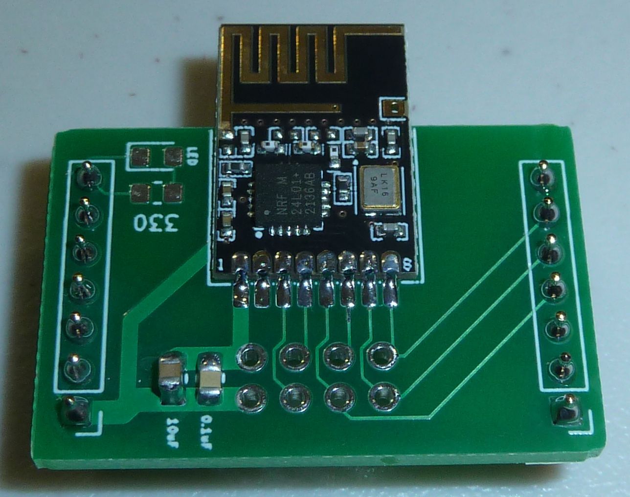
    @Larson What good luck: looks as though the pinout is an exact match for the pinout on my nRF24L01 adapter board for the test platform:
    alt text

    Makes me wonder what those two through-holes are for near the antenna?
    alt text
    Looks as though they are meant for something. Anybody know what those two through-holes are for?


  • Hero Member

    Ignoring the warning about not transmitting for longer than 4ms at a time, I'm presently trying to blast out a continuous stream of packets from the nRF24L01 at 2mbps datarate without pausing between packets. According to the datasheet, one way to do it would be to start sending the first packet while ensuring that the Tx FIFO never empties. However, none of the libraries seem configured for doing that, so it involves working with the nRF24L01 at a lower level. In the worst case, I guess I could settle for a 4ms long packet train if that's the best it can do, but maybe an nRF24L01 equipped with a TCXO could perhaps go longer than 4ms? The 4ms is evidently a PLL limitation, and I'm not sure exactly how the PLL interacts with the crystal, or whether or not a better crystal will lengthen the continuous transmit time.

    Anyone here tried this before? I mean, come on, a lot of people here use the nRF24L01 as their go-to transceiver. Anyone? Anyone? Bueller? Anyone?


  • @NeverDie It has an on-board frequency synthesiser so maybe during tx the temp rises on the substrate and this affects tx frequency stability? So it could be the FS rather than the PLL. Again just guessing here....


  • Hero Member

    I went and did it. I got it to transmit continuously for many seconds before it peters out. And the packets it sends can be received, decoded, and understood. Exactly how long it goes seems to vary from one burst to the next, but a reset gets it going again. Anyhow, it works more than long enough for my purposes. 😄
    tx_continuous.png
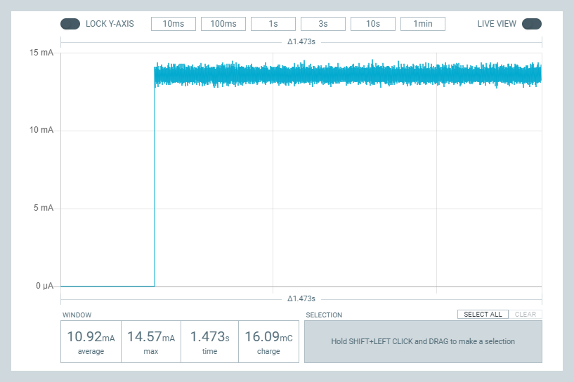
    In case you're wondering why the current draw isn't higher (as it was in earlier pictures), it's because I turned the power all the way down to minimum, since I'm testing at close range.


  • Hero Member

    Also, I'm happy to confirm that the amazon smd nRF24L01 modules that I ordered (see earlier post) have a pinout that matches my nRF24L01 adapters. I've tried it out, and it works:
    smd_nrf24L01.JPG

    That said, what I received is a little bit different than what was pictured in the amazon listing. If you look at the through-holes that are near the antenna, one of them is much smaller on the modules that I received. It's much more like a via than a through-hole.


  • Hero Member

    Lastly, it sounds as though the shortage of legacy chips is going to continue for quite some time:
    Where The Real Chip Shortage Is – 11:53
    — Asianometry

    The TL;DR is that there's little profit in those chips, and so there's no motivation for manufacturers to build expensive new plants to pump out yesterday's technology. I posted recently about the attiny3226, and now I wish I had bought some, because they're now all out of stock everywhere. I'm therefore debating whether to buy some attiny3224's, which lack as many pins, because they're presently in stock but soon will be sold out, jut like the attiny3226's. It might be years before things get back to normal.


  • @NeverDie said in Most reliable "best" radio:

    Makes me wonder what those two through-holes are for near the antenna?

    On ESP8266's, I wondered if the PCB antenna could be cut with a dremel tool and be fitted with an equivalent whip-wire. It would be cheap enough to try. It looks to be that the NRF24's are maybe making that easier? Again, cheap enough to try.

    Thanks for all the updates to https://www.openhardware.io/user/310/projects/NeverDie#view=projects I've been busy updating all the files I've collected. You have been hard at work. All the added *.png and *jpg pictures really help. The *.rar files make it really easy to get into the guts of it all. I got KiCAD downloaded and am looking at the E28 project at the moment. Learning a new CAD tool will be a climb of its own for me.

    For the benefit of others: To extract the *.rar in Windows 10, I downloaded a utility program (WinZip 21-day trial). Maybe everyone already knows that. What I have learned is that getting to the KiCAD files is a three step zip-sandwich procedure:

    1. download and unzip the openhardware *.zip file.
    2. find the *.rar file and use a utility like WinZip to unwrap it.
    3. unzip the resulting *.zip file.

    The resulting four files (*.pcb, *.prl, *.pro, and *.sch) will deliver KiCAD access as a project via the *.pro file. It took me most of the day to learn that. There is probably an easier way.


  • Hero Member

    @Larson said in Most reliable "best" radio:

    unzip the resulting *.zip file.

    Uh, oh. As Bug's Bunnny would say, you may have made a wrong turn at Albuquerque, or, in this case, on step 3.

    There is, I think, a much simpler way. Instead of manually unzipping the .zip file and trying to make sense of the contents, do this instead: in Kicad 6, under the "File..." menu, go to "Unarchive project...." and give it the intact .zip file. It will instantly recreate the entire project on the spot, exactly where I left off with it. It really couldn't be simpler. Try it. You'll like it.

    Regardless, thanks for the feedback. I just now changed the instructions on the openhardware.io projects to make it more clear what to do.


  • Hero Member

    @Larson said in Most reliable "best" radio:

    I wondered if the PCB antenna could be cut with a dremel tool and be fitted with an equivalent whip-wire. It would be cheap enough to try. It looks to be that the NRF24's are maybe making that easier? Again, cheap enough to try.

    No need to guess. It's been done already. Here's one of the mods:
    Cheap DIY NRF24L01 Antenna Modification – 02:48
    — Pete B

    This one looks even better: https://www.instructables.com/Enhanced-NRF24L01/

    I haven't tried either one, but I do believe them when they say it helps improve range a lot.


  • Hero Member

    @Larson said in Most reliable "best" radio:

    You have been hard at work.

    Yup, and although it's jumping the gun, I think I'm ready to reach conclusions. For battery powered nodes, I think for short-range the answer is si24R1, because it offers 2mbps and 7dBm and you can buy tiny, compact modules with in-built PCB antennas for around 50 cents each, as you have already done. Also, mysensors offers over-the-air updates with nRF24L01/si24R1, which is compelling. So, if you have a gateway within range, I see no problem with those radios. For longer range, I think the answer is SX1262 because FCC allegedly allows higher transmit power with spread spectrum, and it has a very large potential link budget. If powered by mains, I'd say ESP8266, which is what I will use to gateway the si24R1 and SX1262 motes. I could test and compare more radios, but I don't have infinite time, so I think that's as far as I'm going to take it for now. If anyone else wants to try more stuff and report back and/or make comparisons, I'd say by all means go for it. For instance, anything that does genuine frequency hopping would be worth looking into. Frequency Hopping would maybe get the best of both worlds, with a combination of high speed, a large link budget, and interference avoidance. This guy does a comparison of LoRa vs Frequency Hopping, and you can see why Frequency Hopping Spread Spectrum seems more compelling than LoRa:

    LoRa Vs Spread Spectrum FHSS 2.4 GHz – 10:13
    — 0033mer

    What's interesting is that the FHSS module he demos actually uses the nRF24L01 chip inside it to accomplish the FHSS! See https://www.ebyte.com/en/new-view-info.html?id=450 So, I take that to mean that with the right software, one could program an MCU to get the nRF24L01 to do FHSS. I do wonder though just how it manages to do it. AFAIK, true FHSS requires psuedo-random changes in frequency while transmitting a single packet, not sending short packets in a pseudo-random sequence of different frequencies. Hmmm.... Maybe it just strips off all the header bytes, and does it that way? Maybe then there would be no difference. I'm guessing maybe that's how they do it. You could compute your own CRC and send the CRC bytes as part of the payload instead of in a separate part of the frame. In fact, that might even be better, because then you could do CRC32, whereas the nRF24L01 hardware encoding seems limited to CRC16. You send what would have been frame bytes as purely payload bytes, creating a kind of virtual Frame. Also, by chopping up the transmission--you could effectively send payloads that are longer than 32 bytes, which is the limit for any single packet on the nRF24L01--by loading and sending more than one pipe's worth of data. This is notionally similar to how I was able to get the nRF24L01 to transmit continuously (see earlier post) without dropping into standby/idle between packets.


  • @NeverDie said in Most reliable "best" radio:

    No need to guess. It's been done already. Here's one of the mods:

    Very interesting. Based on the measurements the author, Pete B, shows, the on-board antenna length is 33.3% the 1/4 Lambda WL. He adds 66.7% for a total 1/4 Lambda. I'll say the same thing is probably true for the ESP8266 antennae lengths. I'm looking forward to trying this with the ESP.

    [Edit: My mistake. I looked at this further. The full 2.4GH WL is 4.92". So, the onboard measured 1.64" WL is a 1/3 WL. The additional 3.28" would bring the total WL to 1.0 * WL. Several simple RSSI tests would show the results. Frist test would be no change for a base case. Then test with the addition. Then one could cut the wire back to 3/4 WL, 1/2 WL, 1/4 WL, then finally remove the antenna to verify the original test, or to inspect for circuit damage.]


  • @NeverDie said in Most reliable "best" radio:

    conclusions

    Yes, I feared that I would be too late to the game to help. I hope to report back with some results after the boat from China arrives. I'd like to do the 2-D map of RSSI values with different radios.


  • @NeverDie said in Most reliable "best" radio:

    Try it. You'll like it.

    I tried about 5 times. I'm able to get to the project files but not through KiCAD (6.0.05) using File/UnarchiveProject so ultimately, I've succeeded. File/UnarchiveProject takes the *.zip file just fine, but it does not deliver the *.pcb, *.prl, *.pro, and *.sch files. File/UnarchiveProject does deliver the *.rar file along with the "design" and "image" directories. File/UnarchiveProject won't take a *.rar file. So ultimately, I use the zip utility to get it. The important part is that I can see the files in KiCAD.

    Reporting from the slow road, Larson.


  • Hero Member

    @Larson said in Most reliable "best" radio:

    @NeverDie said in Most reliable "best" radio:

    conclusions

    Yes, I feared that I would be too late to the game to help. I hope to report back with some results after the boat from China arrives. I'd like to do the 2-D map of RSSI values with different radios.

    Sounds good. The game isn't going anywhere. It'll still be here whenever you're ready. It never ends, and it will outlive both of us.


  • @NeverDie That 'antenna modification' just looks crazy to me, but I have not tried it. However the designers will have spent some time on getting the pcb stripline antenna to be matched to the transmitters impedance. Adding a random bit of wire on the end will screw this up royally.. You never see this on TV antennas or anywhere else for that matter (maybe some nutter with a car aerial made from a coat hanger).

    Also I would expect that the design is to be as wide band as possible but centered on the mid frequency in the range available. So the further you move away from 'centre' frequency (Ch63) then the worse the antenna is likely to perform. But at the power levels used here the effects might be marginal. I have always found moving the RF board a cm or two can make a big difference in link quality.

    Here is the link to the E32 arduino library..... https://www.arduino.cc/reference/en/libraries/ebyte-lora-e32-library/


  • Hero Member

    Regarding the antenna extensions, you raise some good points. The people who posted them seem like they thought it genuinely helped, but maybe I was gullible and was wrong to post the links. If so, I'm sorry. On the other hand, it might take only 5 minutes to try them out and see whether or not they work. A simple trial experiment would maybe settle it one way or the other pretty quickly.

    @skywatch said in Most reliable "best" radio:

    Here is the link to the E32 arduino library..... https://www.arduino.cc/reference/en/libraries/ebyte-lora-e32-library/

    Thanks. What was it you were wanting me to notice about the e32 library? If it was about the FHSS, that was an e34 module in the youtube video.


  • @NeverDie said in Most reliable "best" radio:

    Regarding the antenna extensions, you raise some good points. The people who posted them seem like they thought it genuinely helped, but maybe I was gullible and was wrong to post the links. If so, I'm sorry.

    We are all here to share and learn and help each other out - I was only adding my thoughts on the matter for all to consider.

    On the other hand, it might take only 5 minutes to try them out and see whether or not they work. A simple trial experiment would maybe settle it one way or the other pretty quickly.

    Yes it would, but positioning needs to be carefully maintained to avoid false results.

    @skywatch said in Most reliable "best" radio:
    Thanks. What was it you were wanting me to notice about the e32 library? If it was about the FHSS, that was an e34 module in the youtube video.

    Oh darn it! - I got it mixed up - I am sorry for posting the wrong lib!


  • Hero Member

    @skywatch said in Most reliable "best" radio:

    Yes it would, but positioning needs to be carefully maintained to avoid false results.

    I think for a gateway it could make sense to use two nRF24L01 modules spaced a half wavelength apart. Then for reception you'd get all the benefits of antenna diversity, and for transmission to a particular node you could simply pick the module that receives the most packets out of the two from that node, which should give the better signal path. That could cut down on the sensitivity to positioning by better avoiding null zones.


  • @skywatch said in Most reliable "best" radio:

    That 'antenna modification' just looks crazy to me,

    And that is why it will be fun to test. I corrected my post above and made comments on testing.

    [Edit: It was my bad for drawing people down this dark alley of antenna modifications. I’ve learned much from dark allies and only been beaten-up a few times. Yet, I still go there… to learn. Therefore, I will test it and reply.]


  • Hero Member

    I just now did a current measurement, and, unfortunately, the allegedly smd NRF24L01's on amazon do not appear to be either nRF24L01's nor si24R1's, because the max Tx current is not a match for either:
    Tx_current_smd_nRF24L01.png
    The Tx current is too high to be an nRF24L01, and it's too low to be an si24R1. I'll have to look at some of the alternative datasheets to determine just what it is.


  • @NeverDie I've been playing with KiCAD and working with your BareBones_2AA_Arduino. Given the disucssion on the "Anyone using..." thread about ground planes it jumped out at me that your design uses no ground plane. Of course there isn't any room left either. Does that matter? I see that your radio boards, like the RFM69_900 have solid ground planes.

    To look at further, I looked at the ProMini design by Sparkfun. Pictures are attached of the grounded fills they used. These pictures are of only the top and bottom copper for illustration. I'm thinking this would bother Eric Bogatin and he would say to throw in another layer dedicated to ground signal. Again, do you think it matters?
    TopCu.png BottomCu.png


  • Hero Member

    @Larson I think it probably does matter, but that a dipole antenna may be a good workaround to not having an optimal ground plane. I say that because a number of years ago a group of us on the lowpowerlab forum found that adding a dipole antenna to the rfm69 module resulted in a significant range improvement.

    Part of the problem is that an optimally sized ground plane is actually quite large relative to an otherwise small mote, especially at sub-gigahertz frequencies. So, if you were to build an optimally sized ground plane into your PCB, your mote wouldn't be small anymore. Even a dipole antenna can be so large as to be cumbersome. This antenna: https://lowpowerlab.com/shop/product/193?search=dipole
    was an outgrowth of the discussion and work that the group did, and, as you can see, it's not tiny. However, it might be feasible on a gateway, where size may not matter as much.

    So, short of that, should I try to add more ground plane? I really don't know. More is probably better, but I'm not smart enough to tell you how much difference a marginal increase would make. Adding a dipole antenna very definitely did make a noticeable difference though.

    Maybe somebody reading this who knows more than me can comment.

    Also, part of the reason I didn't add more groundplane was that it would negatively affect the current layout for the two 2.4Ghz horizontal trace antenna readios, which aren't supposed to be mounted over a ground plane. That could be rectified by moving the antenna module to the end of the board, where the trace antenna could hang off the end in empty space, but that's a version 2.0 design. Version 1.0 was just trying to get something ordered from a fab as quickly as possible, and the adapter board placement is something I would change for a v2.0. With that change, there'd be no reason not to do a copper pour and have a nice ground plane--well, within the mote's size constraints.

    There's also more to it than just ground plane. There's the whole matter of impedance, which is hugely important. Smith charts, etc. I don't have more than a superficial grasp on how antennas are supposed to be designed, so I'm really the wrong person to ask about everything that's involved. From what I've read, even the particular dielectric that's used in your PCB can make a meaningful difference. Andreas Speiss did do an episode on how you can use a VNA to tune your antenna better. It might be worth a look. To me it looks like a very deep rabbit hole, and a very steep and very challenging learning curve, so it just depends how far down the rabbit hole you're willing to go. The way I see it, and maybe this is just me, I would hit diminishing returns almost immediately for the amount of effort that's required. That isn't to say that you shouldn't do it though. 😉


  • Hero Member

    @Larson Here's the list of nRF24L01 clones and variants: https://sigrok.org/wiki/Protocol_decoder:Nrf24l01


  • @NeverDie said in Most reliable "best" radio:

    so it just depends how far down the rabbit hole you're willing to go.

    I'm deep in the rabbit hole already and its getting colder and darker. Thank you for your detailed discussion - especially the diminishing-return comment. Yea, I should focus on doing and reporting back - something to show for all I have learned. I remember the 6" dia ground plane idea. Yes, that is a deal-killer. I'd opt for sheet metal befoe building a PCB that big.

    Again, Thank You!


  • Hero Member

    Not completely sure yet, but going down the list of clones/variants datasheets, but it looks as though the amazon smd "nRF24L01" modules may be using the XN297 chip:

    XN297_tx_rx_current_datasheet.png

    I suppose additional measurements, like sleep current and standby current, may either confirm it or not. Also, if it can't support 250kbps, that might also give it away.
    According to the datasheet, it may go as high as 8dBm on Tx, so at least that would be consistent with the "enhanced power mode" advertising in the amazon.com listing.


  • Hero Member

    Well, I checked, and the mystery modules can do 250kbps, so evidently it is not the XN297. That was my best guess, and now I have no idea what it is. The sigrok list of clones and variants hasn't been updated in many years.


  • @NeverDie said in Most reliable "best" radio:

    The sigrok list of clones and variants hasn't been updated in many years.

    Yes, I saw the list of 2 originals and I counted 12 clone/variants. And that list was from 2015 and it is still instructive. If the chips are compatible and deliver value, then it is sufficent for those on the learning curve, like me. Probably not sufficient for market tested commercial products.

    Fun to see the Nordic employee comment about a datasheet error that ended up in a clone. I remember that paper roadmap makers from 50-years ago, like Rand, used to deliberately make mapping errors to catch clones. Times have changed and methods haven't. The die comparisons referenced in links to your link are, again, mind blowing.


  • Hero Member

    @Larson said in Most reliable "best" radio:

    If the chips are compatible and deliver value, then it is sufficent for those on the learning curve, like me

    I think that's the right attitude. The main difference, aside from differences in how they handle ACK (which most software now accommodates for) is that most clones/variants are not as energy efficient as the original. For instance, this particular clone, whatever it is, has a sleep current of something like 1.5ua-1.8ua, as opposed to Nordic's 0.7ua. So, that's worse, but it may not be a deal breaker.

    The newer Nordic nRF5x series chips are definitely a lot more efficient at listening, with receive currents down in the 2.6ma-~5ma range when DCDC conversion is turned on. That compares very favorably to the 15ma and up of the nRF24L01/clones. Of course, a tradeoff is cost and, these days, availability. nRF52805 is "cheap" at around $4, and it's available, so at 4.6ma in RX, it's maybe not a bad choice, considering it includes an RTC and MCU. Its sleep current with RAM retention and RTC is an improvement over the prior nRF52840 flagship. The nRF52805's native Tx power is weak, but for listening it might be adequate. I think I'll order some to try.

    The current flagship is the nRF5340, which is the one that has the 2.6ma Rx current. Presently it is the only one in the nRF53x series.


  • @Larson Will be interested in your results!! 🙂


  • @NeverDie I know what you mean, but "half a wavelength apart would have them in very close proximity with risk of interference. Better if the were 300mm+half a wavelenght apart. But can mysensors cope with 2 gateways on the same frequency? I didn't think that would be possible... Or were you thinking one gateway node with 2x RF modules? Now that would be interesting!


  • Hero Member

    @skywatch said in Most reliable "best" radio:

    @NeverDie I know what you mean, but "half a wavelength apart would have them in very close proximity with risk of interference. Better if the were 300mm+half a wavelenght apart. But can mysensors cope with 2 gateways on the same frequency? I didn't think that would be possible... Or were you thinking one gateway node with 2x RF modules? Now that would be interesting!

    Either way, I suppose.

    Anyway, I ordered the last 10 of the nRF52805's modules from a supplier at just $2.50 each. At that price I would have bought more, but that's all they had. I think that for that price it's a very convenient integrated MCU + radio package for Rx listening and very short-range communication. I look forward to seeing whether the arduino software for the nRF52x arduino library support has noticeably improved since the last time I tried the nRF52x series. I have fond memories of programming it then, and it can only have gotten better since then. Yes? Hopefully? Funny enough a $1 si24R1 will beat it on transmission oomph, but, meh, the nRF52805 wins with 1/3 the Rx current and decently low sleep current, even with built in RTC turned on and full RAM retention.


  • @skywatch Will be interested in your results!

    Here is my proposal for a test of antenna modifications that I will attempt:

    1. Keep it fun, light and fast.
    2. Use ESP8266's (ESP01's or ESP12's) because I've got some to burn.
    3. Antenna modifications only on either receive or transmit (recommendations?)
    4. Based on ESP-NOW protocol - my comfort zone.
    5. Report on RSSI and SNR.
    6. Pick one fixed range so I can keep this close to home and limited in scope.
    7. Most importantly, follow the hack of Pete B. and record
      A. base case original
      B. the 1.0, 0.75, 0.5, 0.25 wave length options
      C. finally test the base case again.

    Any suggestions on other points? I really don't want to burden/distract NeverDie's fine thread here, though I fear I have already. I've never hosted a thread and really don't want to. Perhaps I can post a spreadsheet somewhere.


  • Hero Member

    @Larson said in Most reliable "best" radio:

    I really don't want to burden/distract NeverDie's fine thread here, though I fear I have already.

    No worries. I welcome it. Literally, any content is good content as far as I'm concerned.


  • @NeverDie said in Most reliable "best" radio:

    No worries. I welcome it. Literally, any content is good content as far as I'm concerned.

    You remind me of my favorite teachers/professors. I was lucky to have many.


  • Hero Member

    @Larson Anything that brings more people to the party is a good thing. The more brains brought to bear on any given topic, the better.


  • Hero Member

    @Larson This is kinda bluesky, but I was thinking it would be nice to have not just different radio modules to be pluggable into a test platform, but maybe even different MCU's to be similarly pluggable That way when moving from one version of the test platform to the next, you wouldn't necessarily have to desolder mcu's and other parts. I guess what I'm saying is that maybe the test platform could be either mainly or entirely a backplane that things get plugged into. Especially these days, when finding available MCU's is kinda hit or miss, and you might have to switch to a different MCU because of either price or availability. Anyhow, just putting the idea out there. I'm not at all sure what the best form of such a thing would be, but something that revolves around 2xAA batteries as the form factor makes sense to me.


  • @NeverDie I like the idea. What other mcu's were you thinking of? My limited experience, and supply, is with Atmega328P, Atmega328PB, Attiny 85, Attiny 45, ESP01, and ESP12s. I do have an assortment of PIC chips but can't claim relevant experience as I left that Microchip avenue long ago once I met the easy ArduinoIDE. The downside to multiple mcu’s is, of course, scope creep and even more infinite variations.

    Pluggable? Are you thinking of making a commitment to positions for VCC, GND, several digital pins, maybe an analog pin or two like your Barebones design? Then build PCB's to that footprint for different MCU's? That sounds interesting. Kind of like a MCU/PCB/Radio sandwich.

    I've been studying your Barebones board and enjoy the versatility of the pin locations' multi-functional slots for different projects. Very clever. What brought me to this was that I'm building a radio PCB for yet another radio, the RFM69HCW; the footprint is different than your RFM69HW design. The reason why is that I have 10 HCW's on hand already. I'll share it after I verify that it works. Yesterday, 4 DRF1262's arrived so I'm about to make multiple OSH Park orders. Once they arrive, I'm ready to fab since the flux, the Chipquick, the Keystone AA connectors have all arrived. I've never soldered, or desoldered, a QFN before so I'm anxious about the scavenging of the 328 from a promini. Here we go!

    I am going to have to take a break from my present intensity/study. I’ve got some eldercare things coming up that will dominate my schedule. But I’ll keep in touch.


  • Hero Member

    @Larson said in Most reliable "best" radio:

    What other mcu's were you thinking of?

    Well, that's the thing: not really sure. But tentatively maybe the attiny3224 or the atmega4808/4809. Attiny3324 is very low priced, and presently available, and atmega4808 is more capable than the atmega328p. atmega4808 is same mcu as the atmega4809 (used in the Arduino Nano Every), but with a lower pincount (same as the atmega328p). A counter-argument is to just stick with the atmega328p, since everybody is already familiar with it, and just pay inflated prices for it if you don't already have spares. After all, for a test platform, you don't need many anyway. And scope creep is a very good point.

    [Edit: I just now did a draft. It gives up compactness, because the 14 radio pins have to be run outside of the MCU module to connect with the radio module. Well, it was worth a shot I suppose. To keep it compact, It would need a way to make connections in a very compact way, maybe like the way some of the press-fit connectors on the Pebble watch work. Yet another thing to look into. ]


  • @NeverDie said in Most reliable "best" radio:

    press-fit connectors

    I had to look that up. https://www.connectpositronic.com/en/press-fit-connectors/
    Very interesting. Way too advanced for my Flinstone ways.

    Just today I completed my first KiCAD PCB. It is every bit as challenging as Eagle. Though it does offer some advantages in 'clickability' (my term).


  • Hero Member

    @Larson said in Most reliable "best" radio:

    I had to look that up. https://www.connectpositronic.com/en/press-fit-connectors/

    EEVblog shows an example of one here at time index 6:50:
    EEVblog #761 - Pebble Time Smartwatch Teardown – 32:40
    — EEVblog

    It looks way cool. There must exist something like that which doesn't need ribbon cable, where you can just press two boards together.


  • @NeverDie said in Most reliable "best" radio:

    There must exist something like that which doesn't need ribbon cable, where you can just press two boards together.

    Oh yea, that reminds me of a few teardowns of my own with malfunctioning displays in commercial products like temperature displays. There is some kind of foam boards that are pressed into the display contacts. I figured that they (manufacturers) were doing some complicated LCD pulsing to achieve what was needed much like the POV thing with 7-segment LED displays. Just looked: there are 20 connectors on the ribbon cable, and it was a pretty simple screen on a cheap device. I wanted to dig into it further but there were other shiny-objects that kept getting in the way.


  • Hero Member

    @Larson said in Most reliable "best" radio:

    @NeverDie said in Most reliable "best" radio:

    There must exist something like that which doesn't need ribbon cable, where you can just press two boards together.

    Oh yea, that reminds me of a few teardowns of my own with malfunctioning displays in commercial products like temperature displays. There is some kind of foam boards that are pressed into the display contacts. I figured that they (manufacturers) were doing some complicated LCD pulsing to achieve what was needed much like the POV thing with 7-segment LED displays. Just looked: there are 20 connectors on the ribbon cable, and it was a pretty simple screen on a cheap device. I wanted to dig into it further but there were other shiny-objects that kept getting in the way.

    I think those may be called zebra connectors, if it's what I think you're referring to. I never could re-align those things. Once they're off, it seems like you need some kind of jig to realign them with enough precision. They appear to be pure electrical connectors. You need something else to provide mechanical regidity and hold everything in place.


  • @NeverDie said in Most reliable "best" radio:

    It looks way cool.

    Having a bit more time I watched the entire Dave Jones teardown. Very stunning review. I was feeling quite fancy after my KiCAD design but this 2015 video reminds me who I am. I am Fred Flinstone. only with Youtube. And happy enough with that!


  • Hero Member

    @Larson said in Most reliable "best" radio:

    @NeverDie said in Most reliable "best" radio:

    It looks way cool.

    Having a bit more time I watched the entire Dave Jones teardown. Very stunning review. I was feeling quite fancy after my KiCAD design but this 2015 video reminds me who I am. I am Fred Flinstone. only with Youtube. And happy enough with that!

    Why go half-way? Let's light up some Winston's while we're at it. 😉 Yabba Dabba Doo!


  • @NeverDie said in Most reliable "best" radio:

    I've looked for tiny piezo's that could maybe do this, but they all seem to be different degrees of large. I know it should be possible to be tiny, becaue, for example, a digital wristwatch is able to make audible beeps. On the other hand, after looking at some teardowns, I guess digital watches uses piezo disks that are at least 1/2" in diameter. Hmmmm.... Is that really as small as it gets? Anyone here know? What about hearing aids? Surely they have something smaller. The smallest thing I've found so far has been this: https://owolff.com/page140.aspx?recordid140=534&output=pdf&delay=3000&margin=1cm which is 5mm in diameter. So, I guess forget mounting anything directly to the PCB board: wired discs are the way it's done apparently and then just tuck it somewhere inside the project enclosure.

    I found these recently: https://www.cuidevices.com/micro-buzzers. Digikey seems to carry them but the smallest was listed as "0 quantity in stock" (https://www.digikey.ca/en/product-highlight/c/cui/micro-buzzers). The 4mm square version was available but of course that's just my local digikey, YMMV.


  • @NeverDie said in Most reliable "best" radio:

    As a result, I just now ordered some of these E01-2G4M27D

    Please let us know if they arrive with or without antennas. I've been eyeing them recently but haven't pulled the trigger yet.


  • @NeverDie said in Most reliable "best" radio:

    It does already have 100n (=0.1uF) across the DC power line, extremely near the inputs to the nRF24L01

    Add a 10uF cap there. I found these radios are more stable with enough power to draw on during transmission.


  • @Larson said in Most reliable "best" radio:

    To extract the *.rar in Windows 10, I downloaded a utility program (WinZip 21-day trial).

    7-Zip is an open-source alternative that will do the job equally as well. https://www.7-zip.org/


  • @skywatch said in Most reliable "best" radio:

    @skywatch said in Most reliable "best" radio:
    Thanks. What was it you were wanting me to notice about the e32 library? If it was about the FHSS, that was an e34 module in the youtube video.

    Oh darn it! - I got it mixed up - I am sorry for posting the wrong lib!

    At about 3:12 in the video, he references the Lora E32 and says the pinout is the same and that "the software is compatible". I don't know if he means the library, the code (the module does the frequency hopping) or the Ebyte software for configuring the modules but it would be good to know more about it.


  • Hero Member

    @alphaHotel said in Most reliable "best" radio:

    @NeverDie said in Most reliable "best" radio:

    I've looked for tiny piezo's that could maybe do this, but they all seem to be different degrees of large. I know it should be possible to be tiny, becaue, for example, a digital wristwatch is able to make audible beeps. On the other hand, after looking at some teardowns, I guess digital watches uses piezo disks that are at least 1/2" in diameter. Hmmmm.... Is that really as small as it gets? Anyone here know? What about hearing aids? Surely they have something smaller. The smallest thing I've found so far has been this: https://owolff.com/page140.aspx?recordid140=534&output=pdf&delay=3000&margin=1cm which is 5mm in diameter. So, I guess forget mounting anything directly to the PCB board: wired discs are the way it's done apparently and then just tuck it somewhere inside the project enclosure.

    I found these recently: https://www.cuidevices.com/micro-buzzers. Digikey seems to carry them but the smallest was listed as "0 quantity in stock" (https://www.digikey.ca/en/product-highlight/c/cui/micro-buzzers). The 4mm square version was available but of course that's just my local digikey, YMMV.

    Thanks! Looks as though mouser will be getting some in July: https://www.mouser.com/ProductDetail/CUI-Devices/CMT-322-65-SMT-TR?qs=pBJMDPsKWf2bBoY6kPbMAw%3D%3D


  • Hero Member

    @alphaHotel said in Most reliable "best" radio:

    @NeverDie said in Most reliable "best" radio:

    It does already have 100n (=0.1uF) across the DC power line, extremely near the inputs to the nRF24L01

    Add a 10uF cap there. I found these radios are more stable with enough power to draw on during transmission.

    Yup, already got a 10uF cap on it on the adapter board posted to openhardware.io: https://www.openhardware.io/view/22656/nRF24L01-adapter-board


  • Hero Member

    @alphaHotel said in Most reliable "best" radio:

    @skywatch said in Most reliable "best" radio:

    @skywatch said in Most reliable "best" radio:
    Thanks. What was it you were wanting me to notice about the e32 library? If it was about the FHSS, that was an e34 module in the youtube video.

    Oh darn it! - I got it mixed up - I am sorry for posting the wrong lib!

    At about 3:12 in the video, he references the Lora E32 and says the pinout is the same and that "the software is compatible". I don't know if he means the library, the code (the module does the frequency hopping) or the Ebyte software for configuring the modules but it would be good to know more about it.

    I think what he's saying there is that since the FHSS E34 has a built-in mcu and is operated using AT commands over UART, the comparable UART E32 module uses the same AT commands--which is about the only way I can imagine an E34 could be drop-in compatible as a replacement for the E32. These particular types of modules are advertised and sold as "wireless UARTs", and so the underlying technology is more or less transparent to that kind of solution.


Log in to reply
 

Suggested Topics

  • 4
  • 14
  • 9
  • 5
  • 3
  • 2

36
Online

11.2k
Users

11.1k
Topics

112.5k
Posts