Universal wireless sensor board w/NRF24l01+ and ESP8266 socket - ceech board
-
This board is made for low-power applications and can be used as an universal board for wireless sensor node networks. It can be powered from battery or external source. Dimensions are 2 inch x 2.1 inch.
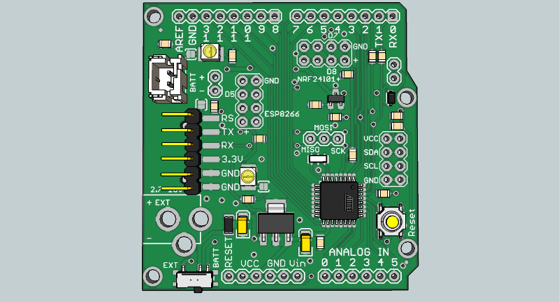
There are three sockets:- for NRF24l01+ module
- for ESP8266 ESP-01
- and an I2C socket
The board is powered with a Microchip MCP1703 3.3V voltage regulator.
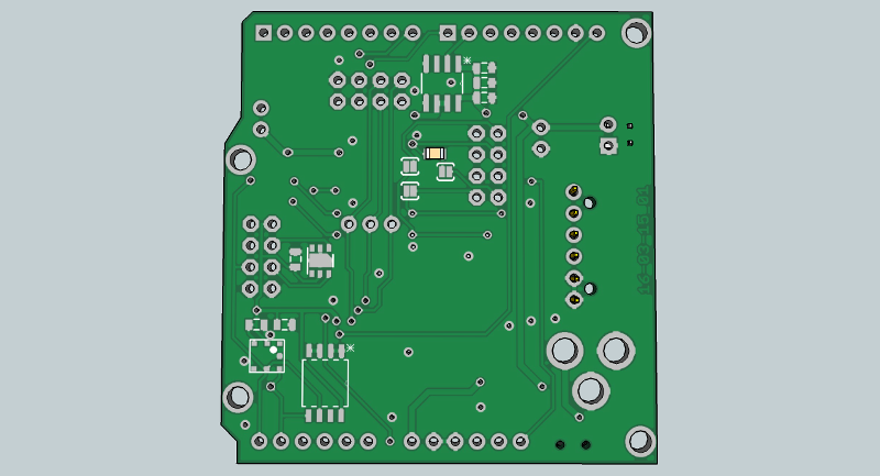
On the back, there is place for BMP180, HTU21, additional EEPROM and for TC series Mosfet driver.
Here is a link to the schematic: http://i.imgur.com/DbALMmf.pngThe board is available here, on http://www.mysensors.org/hardware/ceech
-
@larky Yes, that's right.
It depends. The voltage regulator on this board has lower consumption than the voltage regulator on the one with the solar charger. So this board is more efficient.
However, there is a battery charger on the other board, which charges the battery.
It is a matter of choice, really.
I would say - use this board if you like to keep things simple and do not need high current sensors. Use the board with solar battery charger for sensors that require more power. For example MQ-series air quality sensors tend to use a lot of current. -
Hi @ceech, the link to the board info (above) on the MySensors website still talks about the old board. I assume if we purchase through MySensors we will indeed be getting this updated board? Looks really nice by the way. Thanks very much.
Cheers
Richard -
Hi @ceech, the link to the board info (above) on the MySensors website still talks about the old board. I assume if we purchase through MySensors we will indeed be getting this updated board? Looks really nice by the way. Thanks very much.
Cheers
Richard@hawk_2050 Thank you. Yes, all orders are linked to this, new board. I'll ask @hek to change the description at the next page update.
-
Just received 2 pcs of the board, thanks for quick delivery.
Concerned how to supply them, I don't want to damage them.
What is the voltage range for "BATT" ?
Will power connected to BATT go through the MVP1703 regulator?
I plan to connect BATT to 2 AA batteries (3V) or an separate 3.3 v source on my breadbord.Thanks,
Pär -
The power from either BATT or EXT goes through the voltage regulator. It only consumes 2uA, so it is fairly efficient and its maximum input voltage is 16V. So that is max for BATT as well as EXT. If you would like to power the board directly, then I would suggest connecting the power source via VCC pins on the lower left connector. There are two of them, the second and third from the left. The maximum input voltage for those pins is 5V, or 3V3, if you are going to use radio module.
-
Yes, it can. If you are willing to try, I can send you one board and you can test that if you are up for it. Just post the code here, when you make it work. Send me a message and we can discuss it further if you like.
-
I'm sorry to hear that. Is there something I can do?
The LEDs have solder jumpers next to them. The top one has one to the left, and the bottom one has one to the right. Just pour solder so that both parts of the jumper get connected.
The white connector is Japan Solderless Terminal or JST. I believe it is a XH series with 0.1 inch spacing. The way I connect the wire is I bend the longer ears with pliers over the isolated wire and use solder iron to solder the shorter ears to the stripped wire. -
They are extra. Enjoy.
Hello! It looks like you're interested in this conversation, but you don't have an account yet.
Getting fed up of having to scroll through the same posts each visit? When you register for an account, you'll always come back to exactly where you were before, and choose to be notified of new replies (either via email, or push notification). You'll also be able to save bookmarks and upvote posts to show your appreciation to other community members.
With your input, this post could be even better 💗
Register Login