Skip to content
  • MySensors
  • OpenHardware.io
  • Categories
  • Recent
  • Tags
  • Popular
Skins
  • Light
  • Brite
  • Cerulean
  • Cosmo
  • Flatly
  • Journal
  • Litera
  • Lumen
  • Lux
  • Materia
  • Minty
  • Morph
  • Pulse
  • Sandstone
  • Simplex
  • Sketchy
  • Spacelab
  • United
  • Yeti
  • Zephyr
  • Dark
  • Cyborg
  • Darkly
  • Quartz
  • Slate
  • Solar
  • Superhero
  • Vapor

  • Default (No Skin)
  • No Skin
Collapse
Brand Logo
  1. Home
  2. Hardware
  3. Universal wireless sensor board w/NRF24l01+ and ESP8266 socket - ceech board

Universal wireless sensor board w/NRF24l01+ and ESP8266 socket - ceech board

Scheduled Pinned Locked Moved Hardware
board
41 Posts 9 Posters 22.3k Views 4 Watching
  • Oldest to Newest
  • Newest to Oldest
  • Most Votes
Reply
  • Reply as topic
Log in to reply
This topic has been deleted. Only users with topic management privileges can see it.
  • C Offline
    C Offline
    ceech
    Hardware Contributor
    wrote on last edited by
    #11

    Yes, it can. If you are willing to try, I can send you one board and you can test that if you are up for it. Just post the code here, when you make it work. Send me a message and we can discuss it further if you like.

    1 Reply Last reply
    0
    • S Offline
      S Offline
      shabba
      wrote on last edited by
      #12

      I just want to confirm a few things before I buy :

      1. What is needed to programme this? Can it be done via an FTDI board?
      2. What bootloader is on it?
      3. Besides a sensor and radio (and power) nothing else needs to be added/soldered right?

      Thanks!

      1 Reply Last reply
      0
      • C Offline
        C Offline
        ceech
        Hardware Contributor
        wrote on last edited by ceech
        #13

        @shabba

        1. Yes, it can. With FTDI or similar board. It is the same process as with Arduino Pro mini.
        2. Which is also the bootloader - Arduino Pro or Pro Mini (ATmega328, 8MHz, 3.3V)
        3. Nothing else is needed.
        1 Reply Last reply
        0
        • S Offline
          S Offline
          shabba
          wrote on last edited by
          #14

          Thanks. Ordered a couple.

          1 Reply Last reply
          0
          • S Offline
            S Offline
            shabba
            wrote on last edited by
            #15

            I'm having a slow day so bear with me :-)

            Where do I connect the LEDs? Also what is the name of the white sockets? I want to google procedure for adding wire to the plug part.

            Many thanks :)

            1 Reply Last reply
            0
            • S Offline
              S Offline
              shabba
              wrote on last edited by
              #16

              Warning to others : I blew a radio by connecting a 5V programmer. There seems to be no protection from USB power to the radio.

              1 Reply Last reply
              0
              • C Offline
                C Offline
                ceech
                Hardware Contributor
                wrote on last edited by ceech
                #17

                I'm sorry to hear that. Is there something I can do?
                The LEDs have solder jumpers next to them. The top one has one to the left, and the bottom one has one to the right. Just pour solder so that both parts of the jumper get connected.
                The white connector is Japan Solderless Terminal or JST. I believe it is a XH series with 0.1 inch spacing. The way I connect the wire is I bend the longer ears with pliers over the isolated wire and use solder iron to solder the shorter ears to the stripped wire.

                1 Reply Last reply
                0
                • S Offline
                  S Offline
                  shabba
                  wrote on last edited by shabba
                  #18

                  I see the LEDs and understand now. I had got some loose in the shipping packet and thought I had to solder them onto the board.

                  1 Reply Last reply
                  0
                  • C Offline
                    C Offline
                    ceech
                    Hardware Contributor
                    wrote on last edited by
                    #19

                    They are extra. Enjoy.

                    1 Reply Last reply
                    0
                    • S Offline
                      S Offline
                      shabba
                      wrote on last edited by shabba
                      #20

                      EDITED

                      Nevermind!!

                      "- with CE and CSN pins connected to digital pins 7 and 8 (you must update MyConfig.h with these values). There is a 4.7uF capacitor connected across Vin and GND of the port"

                      AWIA 1 Reply Last reply
                      0
                      • S shabba

                        EDITED

                        Nevermind!!

                        "- with CE and CSN pins connected to digital pins 7 and 8 (you must update MyConfig.h with these values). There is a 4.7uF capacitor connected across Vin and GND of the port"

                        AWIA Offline
                        AWIA Offline
                        AWI
                        Hero Member
                        wrote on last edited by
                        #21

                        @shabba You do not need to update MyConfig.h. Just instantiate MySensor with the right parameters (default is 9, 10).

                        // PIN Radio
                        #define RADIO_CE_PIN    7       // radio chip enable
                        #define RADIO_SS_PIN    8      // CS SS serial select
                        
                        ...
                        
                        MySensor gw(RADIO_CE_PIN, RADIO_SS_PIN);
                        
                        1 Reply Last reply
                        0
                        • epierreE Offline
                          epierreE Offline
                          epierre
                          Hero Member
                          wrote on last edited by
                          #22

                          Hello,

                          I'm trying mine... any idea why the gateway doesn't receive it at 20cm distance ?

                          req node id
                          send: 255-255-255-0 s=255,c=3,t=3,pt=0,l=0,st=fail:
                          sensor started, id 255
                          req node id
                          send: 255-255-255-0 s=255,c=3,t=3,pt=0,l=0,st=fail:
                          req node id
                          send: 255-255-255-0 s=255,c=3,t=3,pt=0,l=0,st=fail:
                          req node id
                          send: 255-255-255-0 s=255,c=3,t=3,pt=0,l=0,st=fail:
                          req node id
                          send: 255-255-255-0 s=255,c=3,t=3,pt=0,l=0,st=fail:
                          

                          z-wave - Vera -> Domoticz
                          rfx - Domoticz <- MyDomoAtHome <- Imperihome
                          mysensors -> mysensors-gw -> Domoticz

                          1 Reply Last reply
                          0
                          • epierreE Offline
                            epierreE Offline
                            epierre
                            Hero Member
                            wrote on last edited by
                            #23

                            @ceech sorry seems the radio was dead ...

                            z-wave - Vera -> Domoticz
                            rfx - Domoticz <- MyDomoAtHome <- Imperihome
                            mysensors -> mysensors-gw -> Domoticz

                            1 Reply Last reply
                            0
                            • epierreE Offline
                              epierreE Offline
                              epierre
                              Hero Member
                              wrote on last edited by
                              #24

                              @ceech I have an issue on a board (lipo+solar) where when I put the programmer it works, when I remove it and leave it on battery it doesn't... battery is 94%, I checked sensors get the energy.. but no more radio it seems, an idea ?

                              z-wave - Vera -> Domoticz
                              rfx - Domoticz <- MyDomoAtHome <- Imperihome
                              mysensors -> mysensors-gw -> Domoticz

                              C 1 Reply Last reply
                              0
                              • epierreE epierre

                                @ceech I have an issue on a board (lipo+solar) where when I put the programmer it works, when I remove it and leave it on battery it doesn't... battery is 94%, I checked sensors get the energy.. but no more radio it seems, an idea ?

                                C Offline
                                C Offline
                                ceech
                                Hardware Contributor
                                wrote on last edited by
                                #25

                                @epierre It is probably a loose contact on the battery connector. Try using a multimeter and check the important connections.

                                1 Reply Last reply
                                0
                                • epierreE Offline
                                  epierreE Offline
                                  epierre
                                  Hero Member
                                  wrote on last edited by
                                  #26

                                  @ceech can you point me to the wirings ? thanks,

                                  z-wave - Vera -> Domoticz
                                  rfx - Domoticz <- MyDomoAtHome <- Imperihome
                                  mysensors -> mysensors-gw -> Domoticz

                                  C 1 Reply Last reply
                                  0
                                  • epierreE epierre

                                    @ceech can you point me to the wirings ? thanks,

                                    C Offline
                                    C Offline
                                    ceech
                                    Hardware Contributor
                                    wrote on last edited by
                                    #27

                                    @epierre Which board are you using?

                                    1 Reply Last reply
                                    0
                                    • epierreE Offline
                                      epierreE Offline
                                      epierre
                                      Hero Member
                                      wrote on last edited by
                                      #28

                                      on this one this is the lipo+solar.

                                      On the other thread, I mistakenly ordered the "standard" version through mysensor website, and had no time till now to test this out... so bard both weren't proposed...

                                      z-wave - Vera -> Domoticz
                                      rfx - Domoticz <- MyDomoAtHome <- Imperihome
                                      mysensors -> mysensors-gw -> Domoticz

                                      C 1 Reply Last reply
                                      0
                                      • epierreE epierre

                                        on this one this is the lipo+solar.

                                        On the other thread, I mistakenly ordered the "standard" version through mysensor website, and had no time till now to test this out... so bard both weren't proposed...

                                        C Offline
                                        C Offline
                                        ceech
                                        Hardware Contributor
                                        wrote on last edited by ceech
                                        #29

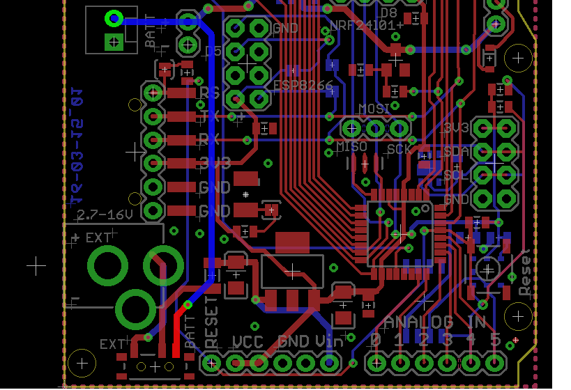
                                        @epierre The battery is connected with the marked trace:
                                        0_1455472919086_board_01.png

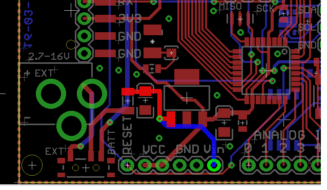
                                        It goes to the switch an over to the voltage regulator:
                                        0_1455473099917_board_02.png

                                        You should measure battery voltage along those lines with respect to the GND. On the other side of the voltage regulator there should be 3V3.

                                        On the side note -- you can use those boards that you've mentioned on the other thread to charge the battery. No problem.

                                        epierreE 1 Reply Last reply
                                        0
                                        • C ceech

                                          @epierre The battery is connected with the marked trace:
                                          0_1455472919086_board_01.png

                                          It goes to the switch an over to the voltage regulator:

                                          0_1455473099917_board_02.png

                                          You should measure battery voltage along those lines with respect to the GND. On the other side of the voltage regulator there should be 3V3.

                                          On the side note -- you can use those boards that you've mentioned on the other thread to charge the battery. No problem.

                                          epierreE Offline
                                          epierreE Offline
                                          epierre
                                          Hero Member
                                          wrote on last edited by epierre
                                          #30

                                          @ceech said:

                                          along those lines with respect to the GND. On the other side of the voltage regulator there should be 3V3.

                                          thanks, but I should not have mixed both, my issue is with the other one.

                                          z-wave - Vera -> Domoticz
                                          rfx - Domoticz <- MyDomoAtHome <- Imperihome
                                          mysensors -> mysensors-gw -> Domoticz

                                          C 1 Reply Last reply
                                          0
                                          Reply
                                          • Reply as topic
                                          Log in to reply
                                          • Oldest to Newest
                                          • Newest to Oldest
                                          • Most Votes


                                          12

                                          Online

                                          11.7k

                                          Users

                                          11.2k

                                          Topics

                                          113.1k

                                          Posts


                                          Copyright 2025 TBD   |   Forum Guidelines   |   Privacy Policy   |   Terms of Service
                                          • Login

                                          • Don't have an account? Register

                                          • Login or register to search.
                                          • First post
                                            Last post
                                          0
                                          • MySensors
                                          • OpenHardware.io
                                          • Categories
                                          • Recent
                                          • Tags
                                          • Popular