Sensebender Micro
-
@Fabien it seems that you have the same problem as me. I ordered a new set of radio modules to test if it is the fault of the radios. I will give feedback here about my progress.
I aleady tried to add capacitors on the radio module but this did not help.
There is also no difference if I power the micro from the FTDI or the battery connector. -
Here are some quite nice repair guides
http://www.circuitrework.com/guides/guides.shtmlMore specifically
http://www.circuitrework.com/guides/5-1.shtml -
looking for some help programming this thing.
I had a pl2303 usb programmer, but it had no DTR, so i orders a new usb programmer
this one is a cp2102 with a DTR line.
but still the same problem. it never uploads the code.
i have the right board, processor and port chosen.
i have tried all the programmers in the IDE but none work.
it just says "uploading" and then eventually errors out.
any suggestions?EDIT: nm i read something about switching tx and rx and i figured what the heck and surprise it worked..
sketch uploaded.. -
Hi @tbowmo
Thanks for bringing this great project to the community.
I'm trying to understand the sensebender's power profile, especially the sleep current.
I have previously done some measurements with the atmega328p (pro mini) + NRF. In addition to that I have also looked at the datasheets for the other components on the sensebender.
It seems the theoretical low sleep current consumption is something like this:
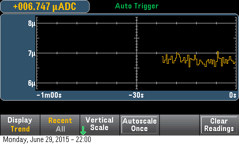
* nrf24l01+    900nA
* atmega328p     5uA (with WD)
* si7021        60nA
* atsha204      30nA
* at23df512c   300nA
  =  Total     6.3uA
The SBMicro seems to draw ~50uA in sleep mode with the default configuration.
I managed to put the flash memory into "ultra deep sleep"(*), causing the total consumption to drop to ~27uA. So there is still around 20uA that is not accounted for.
I've also tried putting the atsha204 into sleep, but that did not make any difference (also confirmed by the specs).
Are there some other settings/sleep modes that have not been enabled yet? What about the atmega itself?
Do any of you have the a sensebender prototype with separate components, and can test sleep current by removing components one
by one? (Before I start cutting traces on my own sensebenders in order to zero in on the target component).Is there something I'm missing?
Datasheets:
ATSHA204
AT25DF512C
Si7021 A20(*) in setup(): flash.initialize(); flash.ultra_deep_sleep() <- From datasheet
-
My NRF's are the same $1 nrf's listed in the mysensors store, so probably fake. But I have still measured them to draw ~900nA in powerDown.
But I think I have found the culprint now. It seems the extra 20uA is caused by Arduino 1.6.5 (it may be that my installation is faulty).
My test setup:
- pro mini
- nrf
- a simple sketch that does gw.sleep(60s)
1st test: sketch compiled & uploaded via Arduino 1.0.5-r2: 6uA
2nd test: sketch compiled & uploaded via Arduino 1.6.5: 24uA -
I'm back with bad news ... My 5th sensebender have a lot of st:fail like the first one. But now I know why !
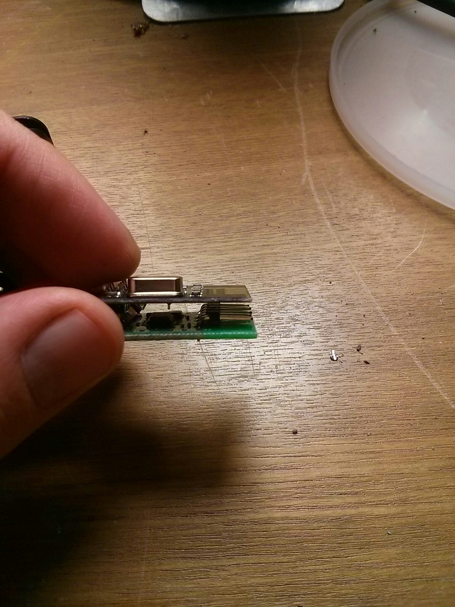
There is only one same things between the two board which fails : The FTDI connector. It's 90° connector and pins are just below the antenna. And I think tunning is not ok.
So, when I go to work I try to remove the FTDI connector and see if connection is better !
-
So now the good news. I "repair" my 1st SenseBender (only two wire but one on the ATMega) and it works (with the same radio wich failed). I remove the FTDI header and everythings is ok. So now I'm sure the problem is the FTDI header near the antenna. And be carefull, we can have the same problem with battery for example. I suppose minimal distance is about 3.2 cm (lambda/4).
But now I have a question : How can I update sketch without header (0° header doesn't fit in case). OTA ? Is ther a tutorial for OTA update with out of the box SenseBenderMicro ?Thank for your help !
-
I tried uploading the sensebender sketch using 1.0.5-r2 with board config "pro mini 328 3.3V 8MHz". The si7021 doesn't work in this configuration, but I managed to get a sleep current of ~6.8uA
I can provide the binary output from the two IDE versions if someone can give me an indication where to find the build binaries.
-
@mvader
I have so far had no problems running my PIR sensors at 3.3v with the following hack.http://techgurka.blogspot.com/2013/05/cheap-pyroelectric-infrared-pir-motion.html
You can not do this with all PIR Sensors from what I understand, but one of the ones listed in the MySensors store is what I've been using. Go down to the bottom of the article.
@gbfromhb said:
@mvader
I have so far had no problems running my PIR sensors at 3.3v with the following hack.http://techgurka.blogspot.com/2013/05/cheap-pyroelectric-infrared-pir-motion.html
You can not do this with all PIR Sensors from what I understand, but one of the ones listed in the MySensors store is what I've been using. Go down to the bottom of the article.
I just wanted to follow up and say thanks for the link/info
i was able to get that working.
surprised that they just don't offer a 3v pin.. it works great the way that link shows
Thanks again!