Sensebender Micro


  • Admin


  • @gloob it's not a radio problem. Same radio works on the others boards.
    @hek I will try to repair the board ...


  • looking for some help programming this thing.
    I had a pl2303 usb programmer, but it had no DTR, so i orders a new usb programmer
    this one is a cp2102 with a DTR line.
    but still the same problem. it never uploads the code.
    i have the right board, processor and port chosen.
    i have tried all the programmers in the IDE but none work.
    it just says "uploading" and then eventually errors out.
    any suggestions?

    EDIT: nm i read something about switching tx and rx and i figured what the heck and surprise it worked..
    sketch uploaded..


  • Hi @tbowmo

    Thanks for bringing this great project to the community.

    I'm trying to understand the sensebender's power profile, especially the sleep current.

    I have previously done some measurements with the atmega328p (pro mini) + NRF. In addition to that I have also looked at the datasheets for the other components on the sensebender.

    It seems the theoretical low sleep current consumption is something like this:

    * nrf24l01+    900nA
    * atmega328p     5uA (with WD)
    * si7021        60nA
    * atsha204      30nA
    * at23df512c   300nA
      =  Total     6.3uA
    

    The SBMicro seems to draw ~50uA in sleep mode with the default configuration.

    I managed to put the flash memory into "ultra deep sleep"(*), causing the total consumption to drop to ~27uA. So there is still around 20uA that is not accounted for.

    I've also tried putting the atsha204 into sleep, but that did not make any difference (also confirmed by the specs).

    Are there some other settings/sleep modes that have not been enabled yet? What about the atmega itself?

    Do any of you have the a sensebender prototype with separate components, and can test sleep current by removing components one
    by one? (Before I start cutting traces on my own sensebenders in order to zero in on the target component).

    Is there something I'm missing?

    Datasheets:
    ATSHA204
    AT25DF512C
    Si7021 A20

    (*) in setup(): flash.initialize(); flash.ultra_deep_sleep() <- From datasheet


  • Admin

    @tlund

    Interesting figures.. are you sure that you've got a genuine nrf24 chip on the radio? Could be a fake with higher power consumption.


  • @tbowmo

    My NRF's are the same $1 nrf's listed in the mysensors store, so probably fake. But I have still measured them to draw ~900nA in powerDown.

    But I think I have found the culprint now. It seems the extra 20uA is caused by Arduino 1.6.5 (it may be that my installation is faulty).

    My test setup:

    • pro mini
    • nrf
    • a simple sketch that does gw.sleep(60s)

    1st test: sketch compiled & uploaded via Arduino 1.0.5-r2: 6uA
    2nd test: sketch compiled & uploaded via Arduino 1.6.5: 24uA


  • Admin

    @tlund

    Hmm could it be some optimization that causes the atmega to not go into deepest sleep mode?

    Maybe someone should have a look at the assembler output from a build with both versions of arduino


  • I'm back with bad news ... My 5th sensebender have a lot of st:fail like the first one. But now I know why !
    There is only one same things between the two board which fails : The FTDI connector. It's 90° connector and pins are just below the antenna. And I think tunning is not ok.
    So, when I go to work I try to remove the FTDI connector and see if connection is better !
    IMG_20150629_160855.jpg


  • Admin

    @Fabien

    That ftdi connector could have some effect on the antenna. I specifically made the area below the antenna empty, so that it wouldn't make any problems with the antenna.


  • So now the good news. I "repair" my 1st SenseBender (only two wire but one on the ATMega) and it works (with the same radio wich failed). I remove the FTDI header and everythings is ok. So now I'm sure the problem is the FTDI header near the antenna. And be carefull, we can have the same problem with battery for example. I suppose minimal distance is about 3.2 cm (lambda/4).
    But now I have a question : How can I update sketch without header (0° header doesn't fit in case). OTA ? Is ther a tutorial for OTA update with out of the box SenseBenderMicro ?

    Thank for your help !


  • I have the FTDI headers on the opposite site and I also get this transmission errors.
    I ordered a new batch of NRF24L01+ modules and will check if the problem still exists.


  • I have my FTDI headers on the other side as well and have no transmission errors.
    I am using genuine NRF+ radios though.
    could be the fakes causing a problem


  • Admin

    I have a male connector on my FTDI thingie, so I just put it in the mounting holes on the micro, and hold it to one of the sides, so it makes contact.


  • @tbowmo

    I tried uploading the sensebender sketch using 1.0.5-r2 with board config "pro mini 328 3.3V 8MHz". The si7021 doesn't work in this configuration, but I managed to get a sleep current of ~6.8uA

    SenseBender.png

    I can provide the binary output from the two IDE versions if someone can give me an indication where to find the build binaries.


  • Admin

    @tlund

    I think it's better if we can get the intermediate asm file from the compiler chain. Will look at it tomorrow evening (I have closed my computer down for the evening today)


  • @gbfromhb said:

    @mvader
    I have so far had no problems running my PIR sensors at 3.3v with the following hack.

    http://techgurka.blogspot.com/2013/05/cheap-pyroelectric-infrared-pir-motion.html

    You can not do this with all PIR Sensors from what I understand, but one of the ones listed in the MySensors store is what I've been using. Go down to the bottom of the article.

    I just wanted to follow up and say thanks for the link/info
    i was able to get that working.
    surprised that they just don't offer a 3v pin.. it works great the way that link shows
    Thanks again!


  • Has anybody built a box for the standard Sensebender Micro with 2 AA batteries yet.
    I would like to get the .stl files if so
    Thanks Doug


  • Hero Member

    @5546dug said:

    Has anybody built a box for the standard Sensebender Micro with 2 AA batteries yet.
    I would like to get the .stl files if so
    Thanks Doug

    Hi Doug,

    @ServiceXP has posted this one: http://forum.mysensors.org/topic/1566/mysensors-sensebender-micro-3dp-case

    Cheers
    Al


  • Has anyone been able to "Include" it to VERA UI7, My Sensebender borad is working fine according to the output from the Arduino terminal window - it request a node id, but will not "include". I'm using the default code already installed in Sensebender Micro board.

    /Kurt


  • Admin

    Yes, it works in UI7. Are you using the correct Vera-branch?

    https://github.com/mysensors/Vera/tree/UI7


  • If somebody is looking for some Sensebenders. They are in sale currently for only 14$

    http://imall.itead.cc/mysensors-micro.html

    Edit:

    I thought I had paid 17$ but they were initially sold for 14$. Sorry.


  • I just order 4 new sensebender, NRF24L01+ (normal and PA+LNA), and Iboard for the gateway. Shiiping is quite expensive (about 31 $)


  • Admin

    @Fabien

    Did you choose DHL as shipping option?


  • I just tried to order something from them and for some reason DHL is now the only available ( US ) shipping option, and it's quite expensive. The sensorbenders I ordered last month were ~$6 shipping, the other components I looked at today via DHL (similar size) were $46, so might be worth holding off a bit until they restore the air-mail option.


  • Admin

    $46 in shipping is a bit hefty. I'll check what's up with their air mail shipping.


  • @hek I have seen it happen once before with them -- wait a few hours, or at most a day and it'll be corrected if history repeats...


  • My last order have cheap shipping costs. But this time I buy lot of things, and shipping price is probably higher du to the weight.


  • Hero Member

    @gloob You fell for the oldest marketing trick in the world. I also missed a heartbeat when pressing on the clearance banner and seeing sensebender there!!!


  • Admin

    @Moshe-Livne @gloob

    The sensebender is shown under the "new stuff" banner 🙂

    (At least in the email I got from Itead :))


  • Hardware Contributor

    Hi,

    @tbowmo or @hek: Could you point me to the right Mysensors bootloader directory please? Is it this one https://github.com/mysensors/Arduino/tree/master/MYSBootloader ? I think yes, but I have seen others links, so I am not sure. I would like to add and test some ulpnode functionalities and would like to start with the right bootloader.


  • Admin

    @scalz

    for the sensebender, we are using DualOptiboot, as we have an external flash onboard, that we can use for OTA firmware updates (it requires dev branch of mysensors though..)


  • Hardware Contributor

    @tbowmo: thank you for your reply. So what is the difference between your link and the one I posted just before (I have not checked yet) ? So, for the moment there is no Mysensors bootloader for stable, isnt it? I just need to add some pin toggle to make some tests (enable dc booster on my board, tune clock, and keep the ota stuff...) and wanted to stick to the stable branch but no problem I will move to dev branch, I think it is time 😃 .
    I don't remember who wanted to use ws2812 in bootloader (maybe it is you?) but there is an implementation in ulpnode bootloader if you are interested : https://github.com/hallard/Arduino-Boards/tree/master/1.0.0/bootloaders/ULPoptiboot


  • Admin

    @scalz

    It's two different bootloaders. the one you have linked to is handling the radio in the bootloader, and can reprogram itself OTA without an external flash attached.

    The one I have linked to, is using an external flash (on the sensebender) and by loading the external flash with a new sketch, it will cause the bootloader to load the content of the external flash, into the internal flash. The same concept is used in LowPowerLabs moteino boards.

    In order to use dualoptiboot, your sketch needs to support the external flash, and write the firmware it receives OTA to it. This functionality is only available in the dev branch as of now. I don't know if @hek has tested it yet? (I have been busy with a lot of other things lately so haven't got around to test it here..)


  • Hardware Contributor

    @tbowmo:it is clear to me now. I will dig in.
    Thank you for your valuable help.


  • I try to make OTA update for sensebender using 1.5 branch sketch on the sensebender (sensebender github sketch from 1.5 branch) and MYSController but it doesn't work. Any idea ?


  • Admin

    @Fabien

    Have you enabled spi flash, and Ota functions in the constructors for mysensors?


  • Admin

    @Fabien MYSController is currently not supporting Sensebender board OTA - however, WIP and beta will be released soon. stay tuned 🙂


  • Admin

    @tekka
    Have you had the chance to get a sensebender board? As I still haven't verified the library code it probably could contain unverified features (== bug). Send me a ping on hangout if you need a board to test on. We should probably combine our effort.

    My last days of vacation has been filled with (family) activities. On my shortlist is the thermostat/HVAC device support (still a bit messy but I hope to get the devices from dev-branch into master together with the hvac thingies). Ping @pjr, @stephenmhall .
    http://forum.mysensors.org/topic/1337/request-new-sensor-type-thermostatically-controlled-switch/7


  • @hek
    I have used the one mentioned here: http://www.mysensors.org/controller/vera

    Still cant include, but I have had these problems before with e.g. a relay or motion sensor - but after several tries it include a appear in the user interface.
    But perhaps the software installed on the board does not use the same frequency as default Sensornet lib's are using?

    /Kurt


  • Thank you @tekka and @tbowmo. I don't change the constructors and if MYS doesn't support OTA, it can't work. I will upload a modified version tonight to be ready when MYSConrtoller will support sensebender.
    I have to upload new sketch with 1.5 branch on gateway too ?


  • Today I received a new batch of radio modules and all problems with transmission fails is gone.


  • Hero Member

    @gloob can you share where you got the good nrf from?


  • @Moshe-Livne just FYI - i ordered all my NRF's from the same place i ordered the sensebender boards from.
    and they were all legit NRF's came in their own boxes and have worked great.
    http://imall.itead.cc/wireless/im120606002.html


  • Admin

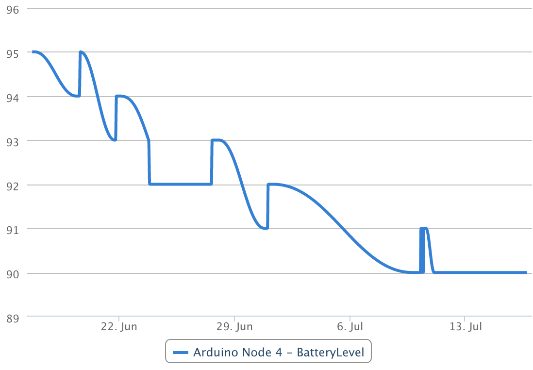
    My Sensebender has been running for a month now with 2xAA with the default sketch (which have improved a bit since then). Battery level has dropped 5%.

    Screen Shot 2015-07-16 at 17.35.12.png

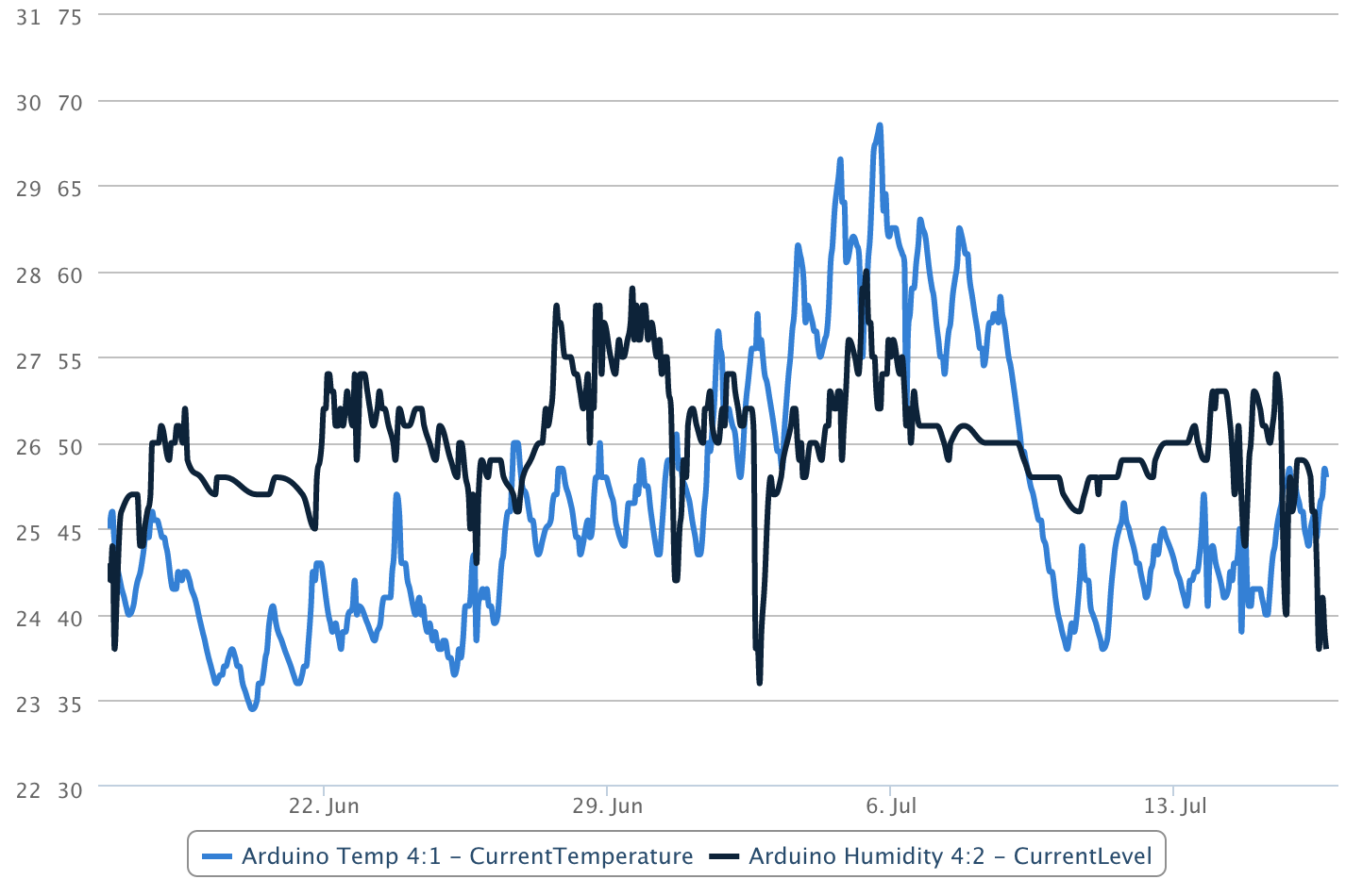
    We've had a few hot days (inside the house) during the summer (Deg C).
    Screen Shot 2015-07-16 at 17.39.57.png


  • Hero Member

    @mvader said:

    @Moshe-Livne just FYI - i ordered all my NRF's from the same place i ordered the sensebender boards from.
    and they were all legit NRF's came in their own boxes and have worked great.
    http://imall.itead.cc/wireless/im120606002.html

    Thanks for the tip! I just ordered some.


  • @hek interesting my 2aa alkaline batteries are down 15% in a month with sketch supplied on board.
    I will keep track. But to grAph I need the Ethernet gw am building it next.


  • Hero Member

    @mvader said:

    @Moshe-Livne just FYI - i ordered all my NRF's from the same place i ordered the sensebender boards from.
    and they were all legit NRF's came in their own boxes and have worked great.
    http://imall.itead.cc/wireless/im120606002.html

    Do they "just work out of the box" or do they benefit from the 10uF capacitor that some boards allegedly seem to need?


  • Admin

    @NeverDie

    I'm not using an extra capacitor on the 3 sensebenders (from itead) that I have in operation at the moment. and they are working without problems.


  • Hero Member

    Batteries usually provide a 'clean' power supply. The capacitor is more useful when there is ripple from the AC adapter.


  • @NeverDie said:

    @mvader said:

    @Moshe-Livne just FYI - i ordered all my NRF's from the same place i ordered the sensebender boards from.
    and they were all legit NRF's came in their own boxes and have worked great.
    http://imall.itead.cc/wireless/im120606002.html

    Do they "just work out of the box" or do they benefit from the 10uF capacitor that some boards allegedly seem to need?

    no cap needed.. just straight to the board.


  • I have just a question about the default sketch.

    Doesn't the following code influence the sleep time?

      // check if we can lower the speed
      if ((measureCount == 5) && highfreq)
      {
        clock_prescale_set(clock_div_8); // Switch to 1Mhz for the reminder of the sketch, save power.
        highfreq = false;
      }
    

    If i lower the clock speed I would expect a lower processing time.

    Also, the threshold for temperature and humidity is set to 0.5 and the humidity is read in percent as an integer. Doesn't this mean that even when the humidity changes by less than 1 percent I get an update of the values. I would expect that the noise of the humidity sensor is around 1%.


  • Admin

    @gloob said:

    I have just a question about the default sketch.

    Doesn't the following code influence the sleep time?

    It's the watchdog that is used for calculating the sleeptime, which is running independently from the CPU oscliator (which is lowered here).

    If i lower the clock speed I would expect a lower processing time.

    Also, the threshold for temperature and humidity is set to 0.5 and the humidity is read in percent as an integer. Doesn't this mean that even when the humidity changes by less than 1 percent I get an update of the values. I would expect that the noise of the humidity sensor is around 1%.

    Humidity is using a running average, it starts with taking average of the previous two measurements, put in the current measurement, and takes a new average (meaning this measurement, and the previous measurement). Then it takes the difference between those two averages, and this needs to be above 0.5.

    In theory it should lower the number of transmissions, if the humidity fluctuates, like: 50%, 51%, 50%.. without the running average, this would trigger 3 transmissions.

    You are welcome to suggest another method of limiting "spurious" transmissions 🙂


  • Hero Member

    @tbowmo hmmm haven't looked at the details in the sketch but suppose we have 50, 50 , 51, 50, 51, 51, 51 wouldn't the results be:
    50, 50 = 50
    50, 50, 51 = 50.3
    50, 51 = 50.50
    50, 51, 50 = 50.50
    51, 50 = 50.50
    51, 50, 51 = 50.6
    50, 51 = 50.50
    50, 51, 51 = 50.6
    51, 51 = 51
    51, 51, 51 = 51

    so no over 0.5 fluctuation?
    I think a threshold would work better. can be by running average but from a fixed, last reported temp.


  • Hero Member

    @hek

    I started it plugged to a vinduino like schema, so I had this :

    Sensebender Micro FW 1.2 - TestMode
    Testing peripherals!
    -> SI7021 : ok!
    -> Flash : failed!
    -> SHA204 : Ok (serial : 01232F36E159E8ADEE)
    Test finished
    ----> Selftest failed!
    

    I read your posts, replaces 1.4.1 libs by 1.5, reflashed it with the demo code and here is what I have:

    Sensebender Micro FW 1.2radio init fail
    

    is that because I don't have a 1.5 serial gateway ?

    I have the socket and the FTDI on the same side so I may avoid the above ?


  • Hero Member

    Finally got around to hooking one of these up last night. I soldered in the socket for the radio and the wires for my battery pack and uploaded the latest version of the sketch by just holding the FTDI connections in place. The sensor is working great. Thanks to @hek and @tbowmo for making it available!

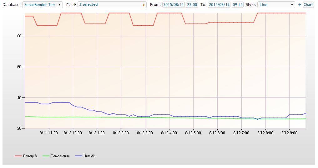
    I'm capturing the data including battery percentage to track how long it will last. One thing is that the battery percentage is jumping around quite a bit. It started at around 93%, dropped below 90, jumped backup to 95, etc. so I'll need to do some investigation as to why. This is happening with brand-new Duracell copper-top batteries. Also, for any future enhancements to the board, I would love to see a couple of mounting holes.
    Sensebender.PNG

    Cheers
    Al


  • Hero Member

    @Sparkman
    I wounder if that is being caused by the loading of the battery and the moment the battery info is being calculated......


  • Hero Member

    @ServiceXp Good point. Maybe for the low values it's transmitting the temp/humidity when it's calculating the battery level. I'll take a look at the sketch to see if that could be the case.

    Cheers
    Al


  • Hello

    I found an error in the sensebender micro sketch in the latest release.

    The calculation of the temperature change is wrong.

    float diffTemp = abs(lastTemperature - (isMetric ? data.celsiusHundredths : data.fahrenheitHundredths) / 100);
    

    needs to be replaced with

    float diffTemp = abs(lastTemperature - (isMetric ? data.celsiusHundredths : data.fahrenheitHundredths) / 100.0);
    

    The division with 100 needs to be 100.0 otherwise the result will be an integer instead of a float value and the difference will be the decimal places of the last temperature.


  • Contest Winner

    This should work as well and might be more clear:

    float diffTemp = abs(lastTemperature - (isMetric ? data.celsiusHundredths : data.fahrenheitHundredths) / 100f);
    

    But I guess it is a matter of taste 🙂


  • Hi guys,
    amazing board! But i have a question: The Arduino IDE offerst two options as destination - 8MHz and 1MHz. Which one should i chose? My board seems to work in general, but not very realiable...


  • Hero Member

    @Stephan-Noller Out of the box, I had to use the 8MHz option to upload the sketch to it.

    Cheers
    Al


  • Admin

    The sensebender is set up to run at 8Mhz. There is an option to build it for 1Mhz, but you have to switch the prescaler yourself in your sketch.

    However I think the current consumption saved by running on 1Mhz vs 8Mhz is very limited on the sensebender, as the oscillator is shut down the majority of time (when we are sleeping the MCU).
    . I have not made any measurements on this yet (busy with a 1000 of other projects)


  • Hero Member

    @ServiceXp Your hunch was correct. I built another Sensebender that only transmitted battery levels, and it's battery levels did not vary at all:

    sb1.PNG

    I then modified the sketch to put a short wait after the temp & humidity are sent to allow the voltage level to recover and the battery levels do not fluctuate so far. However, I'm thinking it would be better to always measure right after a transmit, but not sure if that's easy to do.

    Cheers
    Al


  • Hero Member

    @Sparkman Thanks for the follow up.


  • Hero Member

    @hek can anyone help me, no unit is functionnal so far...

    @epierre said:

    @hek

    I started it plugged to a vinduino like schema, so I had this :

    Sensebender Micro FW 1.2 - TestMode
    Testing peripherals!
    -> SI7021 : ok!
    -> Flash : failed!
    -> SHA204 : Ok (serial : 01232F36E159E8ADEE)
    Test finished
    ----> Selftest failed!
    

    I read your posts, replaces 1.4.1 libs by 1.5, reflashed it with the demo code and here is what I have:

    Sensebender Micro FW 1.2radio init fail
    

    is that because I don't have a 1.5 serial gateway ?

    I have the socket and the FTDI on the same side so I may avoid the above ?


  • Admin

    @epierre said:

    is that because I don't have a 1.5 serial gateway ?

    Gateway version shouldn't matter if you get this message at startup of node.

    I have the socket and the FTDI on the same side so I may avoid the above ?

    I don't understand what you mean.


  • Hero Member

    @hek said:

    @epierre said:

    is that because I don't have a 1.5 serial gateway ?

    Gateway version shouldn't matter if you get this message at startup of node.

    what should I do from there ?

    I have the socket and the FTDI on the same side so I may avoid the above ?

    I don't understand what you mean.

    this was related to the electric perturbation with headers close to the radio


  • Hero Member

    @epierre Can you confirm the settings you used in the IDE to program it? Are you sure there are no solder bridges where you soldered the radio or socket for the radio? Have you tried powering it with a couple of AA batteries after you uploaded the sketch?

    Cheers
    Al


  • Hero Member

    Today I integrated my first 2 sensebender micros into my homeautomation and they almost worked out of the box. I like this board really much! Good work, I will order more!

    Pitfall:
    When updating the mysensors lib from 1.4.x to 1.5 the sensor failed to get an id from the controller which btw was still running on 1.4.x.
    After having done all the things like "clearing eeprom", "soldering a capacitor to the radio" and so on... I noticed that I changed the RF_CHANNEL from the default 76 to some other value in MyConfig.h some months ago (probably for some paranoia reason).
    When updating to lib 1.5 the sensor sketch got the 76 while the gateway still used the other one and so the communication between both failed. After changing the radio channel to the one the controller uses, everything worked very quickly!

    Probably this post helps someother guy who fell into the same trap.


  • Hi,

    My sense bender works perfect when sending directly data directly to serial gateway (vera 5), however when I move it out of range to the serial gateway and want it to connect to my repeater node it does not want to discover the repeater node. Anyone else had this problem?


  • Admin

    Remember that it takes a few ( ~5) failed transmits until it searches for a new parent node.


  • @johnr

    Is your repeater node still on MySensors 1.4? I had a similar problem and upgrading to 1.5 solved it.


  • You are probably right. I did not realise sense bender was pre loaded with 1.5

    I think easiest for me would be to downgrade sense bender to 1.4 is it possible?


  • Admin

    Sensebender is still on 1.4, as we haven't prepared new firmware for it yet.

    Mysensors 1.4 and 1.5 should be compatible with each other, right @hek ?


  • Admin

    Yes, it should.

    But as @Dewalt says, there was a bug in repeater functionality. So upgrading the repeater is a good tip.


  • Upgrading repeater to 1.5 solved this issue. Thanks for the quick help. 1.4 sensors communicate OK with the 1.5 repeater as far as I can see right now.


  • I try to make a 3D box for SenseBender Micro with CR123 battery.
    Screenchot :
    Boitier.png


  • first print test : IMG_20150921_230740.jpg
    IMG_20150921_230820.jpg


  • Admin

    @Fabien

    Nice work, what is the dimensions of the enclosure?


  • @mvader said:
    question about the default sketch for this board.
    if i read correctly

    
    // How many milli seconds between each measurement
    #define MEASURE_INTERVAL 60000
    
    // How many milli seconds should we wait for OTA?
    #define OTA_WAIT_PERIOD 300
    
    // FORCE_TRANSMIT_INTERVAL, this number of times of wakeup, the sensor is forced to report all values to the controller
    #define FORCE_TRANSMIT_INTERVAL 30 
    
    // When MEASURE_INTERVAL is 60000 and FORCE_TRANSMIT_INTERVAL is 30, we force a transmission every 30 minutes.
    // Between the forced transmissions a tranmission will only occur if the measured value differs from the previous measurement
    
    // HUMI_TRANSMIT_THRESHOLD tells how much the humidity should have changed since last time it was transmitted. Likewise with
    // TEMP_TRANSMIT_THRESHOLD for temperature threshold.
    #define HUMI_TRANSMIT_THRESHOLD 0.5
    #define TEMP_TRANSMIT_THRESHOLD 0.5
    

    if temps don't change more than .5 i shouldn't see a transmit but once every 30 minutes
    i have 2 running right now
    and both send temp and humidity every 1-2 minutes and the numbers are the same or in some cases only different by .1
    i have it set to .5 so the question is

    1. why does it transmit every minutes when the temp and humidity are the same
    2. why is it transmitting even with as little as .1 change
      1 board is running 1.2 and the other is running the 1.3 sketch from git
      Battery however does transmit every 60 minutes as it's supposed to.,
      thx

  • Admin

    @mvader

    Have you tried to hook up a serial connection to your sensebender? It writes the difference from the last transmitted measurement, everytime a new measurement is taken (every minute).


  • @tbowmo 47x37 height : 27
    I will make some improvment (can not test, my printer is in maintenance mode !) and post files for others.


  • @tbowmo said:

    @mvader

    Have you tried to hook up a serial connection to your sensebender? It writes the difference from the last transmitted measurement, everytime a new measurement is taken (every minute).

    so if i want it to transmit less frequently (save battery?) i would increase the measure interval. correct?
    I have some situations where i want frequent measuring (1 minute), and some where 15 minutes or 30 minutes would do fine.


  • Admin

    @mvader

    Yes, you could save battery, by changing to 10/15 minute check interval..

    But still, the interesting thing is why it transmits every minute.. That's why I would suggest to check the serial output..


  • Hero Member

    There is an explanation to the problem further up in the thread:

    @gloob said:

    Hello

    I found an error in the sensebender micro sketch in the latest release.

    The calculation of the temperature change is wrong.

    float diffTemp = abs(lastTemperature - (isMetric ? data.celsiusHundredths : data.fahrenheitHundredths) / 100);
    

    needs to be replaced with

    float diffTemp = abs(lastTemperature - (isMetric ? data.celsiusHundredths : data.fahrenheitHundredths) / 100.0);
    

    The division with 100 needs to be 100.0 otherwise the result will be an integer instead of a float value and the difference will be the decimal places of the last temperature.


  • Admin

    @korttoma

    thanks for helping my memory 🙂


  • @korttoma i did see that. but your saying that is what is causing it to transmit every 1 minute?


  • Hero Member

    @mvader yes, it is rounding the temperature difference to the nearest degree so the difference is almost always more then the 0.5.


  • Admin

    Just a hint, itead studio is starting a sale with 10% off on all imall items.. So maybe it's time to buy some Christmas presents for the inner geek 🙂


  • Oh no! Lousy timing, I just bought some...
    ... in fact, they arrived today.

    Speaking of which, whilst I got them to run the default sketch, do I actually need a programmer to do anything different, or can this be done OTA (from a Mac) ?


  • Admin

    @akbooer

    The default sketch doesn't support OTA, as it wasn't available in the stable branch at the time of launch


  • @tbowmo Good sales but did not see the Sensebender too bad .


  • Admin


  • Hero Member

    @hek I've soldered a second unit to compare, same error, I flashed back the sensebender version from the examples and on both I am stuck here: "Sensebender Micro FW 1.2radio init fail"

    Gateway is 1.5 BTW, one radio is from itead the other not.


  • Hero Member

    @Sparkman said:

    @epierre Can you confirm the settings you used in the IDE to program it?

    1.6.5 version

    Are you sure there are no solder bridges where you soldered the radio or socket for the radio?

    same behavior on two units

    Have you tried powering it with a couple of AA batteries after you uploaded the sketch?

    not yet but why should that change anything ?


  • This post is deleted!


  • Just tried out my first Sensebender...
    soldered pins and battery power...
    turn on...
    led flashes once...
    start inclusion...
    3 devices...
    Vera restarts (actually, it's openLuup running on an Arduino Yún)...
    there they are...
    and updating every minute!

    Thanks so much to all who made this level of sophistication so easy!! (Z-wave was never this simple!)

    Whilst I need a couple of temp/humidity sensors, I also need to reflash one as a 4-switch sensor. Can I do this with an Arduino Uno configured with the ArduinoISP sketch as described here ?
    https://www.arduino.cc/en/Tutorial/ArduinoISP

    Any advice or useful pointers? Thanks.


  • Admin

    @epierre

    What do you use as supply voltage for the thing? What is the output from testmode?

    Did you add a capacitor on the radio module? How did you mount them together? (picture?)


  • Admin

    @akbooer

    Should be doable with an arduino as isp. Another option is to use the serial upload.


Log in to reply
 

Suggested Topics

  • 3
  • 109
  • 164
  • 2
  • 109
  • 5

15
Online

11.4k
Users

11.1k
Topics

112.7k
Posts