Irrigation Controller (up to 16 valves with Shift Registers)
-
@Sergio-Rius said:
the dimmer control in Domoticz it's complex and sometimes requires more than one click to activate
Can you elaborate on this? In my setup the Dimmer is as reliable as any other control. Main limitation is that the standard dimmer can only assume 16 "states"/ values.
@AWI said:
Can you elaborate on this? In my setup the Dimmer is as reliable as any other control. Main limitation is that the standard dimmer can only assume 16 "states"/ values.
The dimmer is reliable. I was talking of interface widget being complex. In Domoticz, to activate one zone you would have to first click, and when the popup appears, click again on the blue (sphere?) for it to start.
In Imperihome, you would have up to 32 rgb dial indicators on your page and still don't get the current set value, and when you set it on, most of times it doesn't respect the current intensity value.And that doesn't solve the double timing setup nor the naming.
I always like to apply the KISS rule to my developments and avoid to depend on other systems. Specially if they don't walk in the same direction. Imagine that in the future the dimmer system changes, for example, into a hue pallete.And it's true that mysensors and domoticz is lacking a sensors configuration system.
-
@AWI said:
Can you elaborate on this? In my setup the Dimmer is as reliable as any other control. Main limitation is that the standard dimmer can only assume 16 "states"/ values.
The dimmer is reliable. I was talking of interface widget being complex. In Domoticz, to activate one zone you would have to first click, and when the popup appears, click again on the blue (sphere?) for it to start.
In Imperihome, you would have up to 32 rgb dial indicators on your page and still don't get the current set value, and when you set it on, most of times it doesn't respect the current intensity value.And that doesn't solve the double timing setup nor the naming.
I always like to apply the KISS rule to my developments and avoid to depend on other systems. Specially if they don't walk in the same direction. Imagine that in the future the dimmer system changes, for example, into a hue pallete.And it's true that mysensors and domoticz is lacking a sensors configuration system.
@Sergio-Rius Think I understand ;) and keep my systems as autonomous and simple as possible.
The route with S_INFO/V_TEXT won't bring you any luck, regarding the customization to be done in Domoticz to get values in V_TEXT (LUA / JSON).
btw. Like your sketch :thumbsup: -
@Sergio-Rius Think I understand ;) and keep my systems as autonomous and simple as possible.
The route with S_INFO/V_TEXT won't bring you any luck, regarding the customization to be done in Domoticz to get values in V_TEXT (LUA / JSON).
btw. Like your sketch :thumbsup: -
@AWI
You'r right, that's not the best route. But until we have sensors configuration routines... ;)
Will we have? :grimacing:@Sergio-Rius Don't expect too much in either MySensors/ Domoticz unless you know of a "industry standard" approach which can be implemented with reasonable efforts by the community..
-
@Sergio-Rius Don't expect too much in either MySensors/ Domoticz unless you know of a "industry standard" approach which can be implemented with reasonable efforts by the community..
@AWI said:
@Sergio-Rius Don't expect too much in either MySensors/ Domoticz unless you know of a "industry standard" approach which can be implemented with reasonable efforts by the community..
Are you saying that Domoticz primary focus is to follow existing industry standards? Some times you need to shift away from the standards. Giving users more options will only increase the software's user base. If it were me, I'd rather become the standard than chase it.
-
@dbemowsk said:
How do you use this array with Domoticz to send the zone times to the controller? It looks like you are setting the valve names and times within the sketch as if they are permanently set on the controller.
Yes, that was the part where we supposedly had to join our sketches. Just getting all the array contents from an S_INFO. Perhaps using some Json to array conversion. Should be some library for conversions there.
I am a little confused about the presentation of the S_BINARY, Elm.Name:
        myElement Elm = myElements[i];
        present(i, S_BINARY, Elm.Name);
My understanding is that S_BINARY is just for on/off which I am guessing is the on/off control for the zone. What does the Elm.Name do though?
Elm.Name assigns a name to the valve. And presents to Domoticz. Still doesn't exists a way to get from domoticz.
Do yoy have a way to set valve times from within Domoticz?
Again, still doesn't....
I also noticed that you removed the time sync with the receiveTime() function. This tells me that you are not sending the current time to the controller. Any reason for this?
Yes. as I said it was so complicated for me to integrate the "stand-alone functions" that use loop cycles for running the menu. I planned to make dedicated functions for it, but didn't have time.
As for my sketch, I am thinking of another route to go with this where I can send the valve times and names using a single S_INFO sensor. I plan to use some of the information from this forum post: Splitting a string. The idea is to use a separator character such as ":" or "|" to create a pseudo array using a single string. Doing this will eliminate 2 S_INFO sensors for each zone, and also make it easier to configure. I am going to work on this tonight and see where I get with it.
And why not using this approach on a single S_INFO, that could feed the array I have in my sketch?
@Sergio-Rius said:
And why not using this approach on a single S_INFO, that could feed the array I have in my sketch?
The main part of my new approach is this bit here:
      if (message.type == V_TEXT)
      {
        String valveMessage = String(message.data);
        char* valveData = &valveMessage[0]; //.c_str();
        DEBUG_PRINT(F("Recieved valve data:"));
        DEBUG_PRINT(i);
        DEBUG_PRINT(F(" = "));
        DEBUG_PRINTLN(valveMessage);

        char* var = strtok(valveData, "|");

        int variable1 = atoi(var); // RUN_ALL_ZONES time

        if (variable1 != allZoneTime[i])
        {
          allZoneTime[i] = variable1;

          zoneTimeUpdate = true;
        }

        var = strtok(NULL, "|");

        int variable2 = atoi(var);// RUN_SINGLE_ZONE time

        if (variable2 != valveSoloTime[i])
        {
          valveSoloTime[i] = variable2;

          zoneTimeUpdate = true;
        }

        var = strtok(NULL, "|");

        String newMessage = String(var);
        if (newMessage.length() == 0)
        {
          DEBUG_PRINT(F("No Name for "));
          DEBUG_PRINTLN(i);
          break;
        }
        if (newMessage.length() > 16)
        {
          newMessage.substring(0, 16);
        }
        valveNickName[i] = "";
        valveNickName[i] += newMessage;
        DEBUG_PRINT(F("Recieved name "));
        DEBUG_PRINT(i);
        DEBUG_PRINT(F(" called: "));
        DEBUG_PRINTLN(valveNickName[i]);
      }
      receivedInitialValue = true;
    }
  }
The key is using strtok() to split the incoming string into it's parts. The code that I posted from my tests seems to work, at least from what I have tested so far. It uses one S_INFO sensor for each zone to carry the 3 parts that would be the V_VAR1 - V_VAR3 info in the original sketch. Granted it is only for 1.5, but if you can use anything from my 1.5 sketch in your 2.0 sketch, feel free.
-
Hi first Great projekt. All the things is Just ordred from eBay. But i Wonder what the yellow component is.
And mayby a tuturial have to make a complete HA kontroller. And have to set i Up. Rigtig now i have a raspberry pi with calaos. But i Dont know have to the it Up with the system.
Hope there is some help in here :)
-
I put together an extension of the multi-Relay controller for use as a controller for your irrigation project if you have more zones than available pins on your Arduino.
This sketch features the following:
- Allows you to cycle through All zones or individual zone control.
- Use the (n+1)th device to activate each zone in numeric sequence (zero to n) using
Variable1 as the "ON" time in minutes in each of the vera devices created. - Use the individual zone controller to activate a single zone. This feature uses
Variable2 as the "ON" time for each individual device/zone. - Connect according to pinout in the sketch and uses an 74HC595 (or equiv) Shift Register as to
allow the MySensors standard radio configuration and still leave available digital pins - Compiles to ~12,000 Bytes, so will run on any Arduino
- Turning on any zone will stop the current process and begin that particular process.
- Turning off any zone will stop the current process and turn off all zones.
- Sketch must collect your desired intervals so it takes several minutes to startup.
- If you change your desired time intervals for your zones, simply restart your arduino
and it will self update to reflect those changes.
Example, I am using with 8 relays:
This will create 9 devices. Zero through 7 are the individual relays. Eight is the Sequencer, so to speak (refer to attachment).
Once you create this and add it using the gateway, go to each of zero through 7 and edit Variable1 and Variable2 for what time you want to use for the Sequencer or Zone respectively. Then save the settings. Then, restart your arduino; your arduino will extract these settings and save them to an array.
When you turn on device 8 (aka the Sequencer) the relays will actuate in order from zero to seven, each one staying on for the period entered in the Variable1 field. There is a 5 second delay at the start of a new zone to allow for the valves to hydraulically reset.
When you turn on any of devices zero through 7, it will run that zone only for the period of time entered in Variable2.
Selecting any new zone (0-8) will stop the current process and start as per above.
Hope you have a use for it. If you see any opportunity to improve, or find a bug, let me know.
Jim
modified. Attached wrong file, whoops!I love your programming skills, it is superb. Haven gone through your video, l was happy and l needed a modification to your setup. I want to use the arduino to power my irrigation with the following function.
Arduino with soil moisture sensor check. once the soil is dry, arduino to switch on the electric 1horse power pumping machine and at the same time open the solenoid valve to irrigate at a specified timing.
As per powering the pumping machine, arduino should check if there is public electricity supply before switching on the pump and if there is no public power supply then it should switch on the power generating set to power the pumping machine and solenoid valve.
After the sensor has confirmed that the soil is wet and moist, then arduino stops the pumping machine and then closes the electric 220v solenoid valve.
Second task.
Overhead Mist Sprayer (uses a different AC 1horse power pump)
A sensor to check when the sun temperature is 35 or 40 degrees or any programmed temperature and switch on the pumping machine to power the sprayer for a specified timing. Also arduino should should check if there is public electricity supply before switching on the pump and if there is no public power supply then it should switch on the power generating set to power the pumping machine.
Also irrigation records of time and dates and other function will be added up in the setup.
I like to know the hardwares l will need for this project, a guide and codes. I appreciate this .
Thanks
-
I love your programming skills, it is superb. Haven gone through your video, l was happy and l needed a modification to your setup. I want to use the arduino to power my irrigation with the following function.
Arduino with soil moisture sensor check. once the soil is dry, arduino to switch on the electric 1horse power pumping machine and at the same time open the solenoid valve to irrigate at a specified timing.
As per powering the pumping machine, arduino should check if there is public electricity supply before switching on the pump and if there is no public power supply then it should switch on the power generating set to power the pumping machine and solenoid valve.
After the sensor has confirmed that the soil is wet and moist, then arduino stops the pumping machine and then closes the electric 220v solenoid valve.
Second task.
Overhead Mist Sprayer (uses a different AC 1horse power pump)
A sensor to check when the sun temperature is 35 or 40 degrees or any programmed temperature and switch on the pumping machine to power the sprayer for a specified timing. Also arduino should should check if there is public electricity supply before switching on the pump and if there is no public power supply then it should switch on the power generating set to power the pumping machine.
Also irrigation records of time and dates and other function will be added up in the setup.
I like to know the hardwares l will need for this project, a guide and codes. I appreciate this .
Thanks
There are several examples out there (either here or in the Arduino forum) of how to combine sketches for added functionality. Fortunately, you are starting with my code that is already non-blocking and uses little in the way of system resources so it should be straightforward from here.
The community here (including me) can assist in giving you what you want.
first thing is the hardware... assuming your using metric means you are 220VAC... you need a person familiar with mains switching to help you out there!
-
Hi first Great projekt. All the things is Just ordred from eBay. But i Wonder what the yellow component is.
And mayby a tuturial have to make a complete HA kontroller. And have to set i Up. Rigtig now i have a raspberry pi with calaos. But i Dont know have to the it Up with the system.
Hope there is some help in here :)
@impertus said:
Hi first Great projekt. All the things is Just ordred from eBay. But i Wonder what the yellow component is.
And mayby a tuturial have to make a complete HA kontroller. And have to set i Up. Rigtig now i have a raspberry pi with calaos. But i Dont know have to the it Up with the system.
Hope there is some help in here :)
@BulldogLowell -
@impertus said:
Hi first Great projekt. All the things is Just ordred from eBay. But i Wonder what the yellow component is.
And mayby a tuturial have to make a complete HA kontroller. And have to set i Up. Rigtig now i have a raspberry pi with calaos. But i Dont know have to the it Up with the system.
Hope there is some help in here :)
@BulldogLowell@impertus said:
But i Wonder what the yellow component is.
Where are you seeing the yellow component? Maybe it's the LED? Can you post a picture?
My "How To" home automation video channel: https://www.youtube.com/channel/UCq_Evyh5PQALx4m4CQuxqkA
-
@impertus said:
But i Wonder what the yellow component is.
Where are you seeing the yellow component? Maybe it's the LED? Can you post a picture?
-
-
@BulldogLowell Thx :)
Is this the rigth setup.
Irrigationcontroller <-----> Radio + ethernet (Gateaway) ------> Router + Wifi ------> RaspB with (Calaos HA controller)
Wifi -----> Calaos Mobile app
How does the HA controller detects the signal from the irrigation controller? some mystisk setup :) or plug an play..
What HA will you use (Opensouce)(With mobil function)
@BulldogLowell Ha! Unfortunately I'm fresh out of those...
@impertus Both @BulldogLowell and I use Vera as our home automation controller (not open source). My setup looks like: Irrigation Controller <> Ethernet Gateway <> Vera <> Vera Mobile App (usually AutHomationHD). I haven't tested any other controllers with this device but reading up a little in this forum post it appears that some people have got it to work with Domoticz.
My "How To" home automation video channel: https://www.youtube.com/channel/UCq_Evyh5PQALx4m4CQuxqkA
-
@BulldogLowell Ha! Unfortunately I'm fresh out of those...
@impertus Both @BulldogLowell and I use Vera as our home automation controller (not open source). My setup looks like: Irrigation Controller <> Ethernet Gateway <> Vera <> Vera Mobile App (usually AutHomationHD). I haven't tested any other controllers with this device but reading up a little in this forum post it appears that some people have got it to work with Domoticz.
@petewill yeahh i did a little bit of surfing on the forum. And felt over Domoticz. I see that also can run on RaspBerryPi. So think i will give that at try. It will be nice with a newbie guide how to setup my sensors to Domo. step by step..
now im waiting for the mailman with all my components :)
-
Hi, I've done recently this setup - it works greate with domoticz and Raspberry Pi 0.
After some tests I findout that when I plug in power - sometimes all, sometimes 3 or 4 relays are turning ON for 1second.
If that happend my 24V power adapter will be in trash. How to prevent that? Do I need to add something in code (I'm not a programmer)?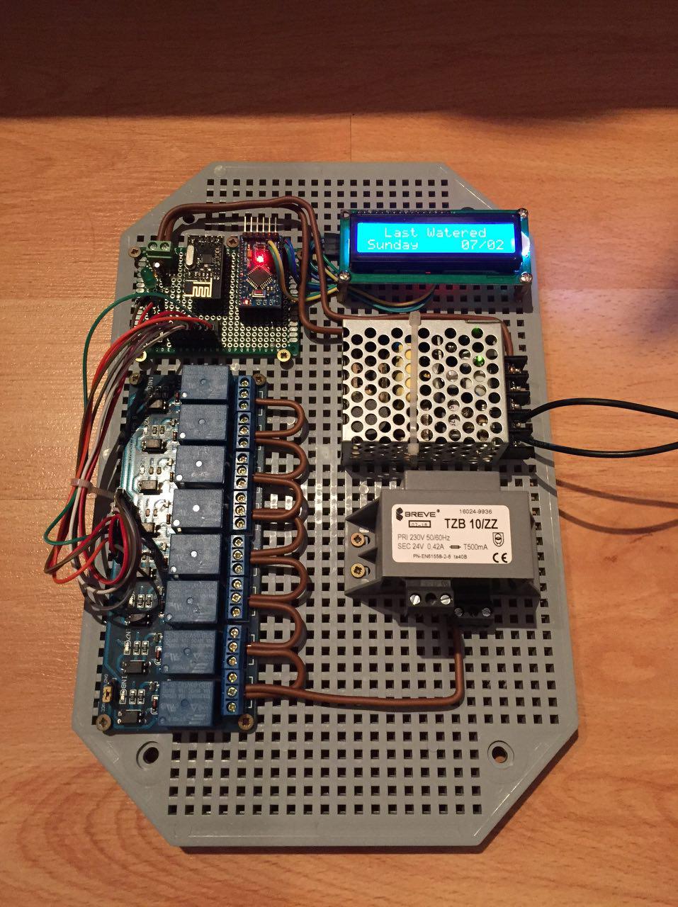
-
Hi, I've done recently this setup - it works greate with domoticz and Raspberry Pi 0.
After some tests I findout that when I plug in power - sometimes all, sometimes 3 or 4 relays are turning ON for 1second.
If that happend my 24V power adapter will be in trash. How to prevent that? Do I need to add something in code (I'm not a programmer)?try adding a delay in various places in setup() start with 5 or even 10 seconds.
-
ok, I just get back from Hackerspace. Some people fix this issue:
SN74HC595 - 13 pin (OE from datascheet) - remove GND and then add pull up 1k resistor and wire it to Arduino pin 6and software, added three lines in code:
  const int outputEnablePin = 6;

  pinMode(outputEnablePin, OUTPUT);
  digitalWrite (outputEnablePin, LOW);
put them after 190 line https://github.com/mysensors/MySensorsArduinoExamples/blob/master/examples/IrrigationController/IrrigationController.ino
should be like that:
<some code>
 //Setup Shift Register...
const int latchPin = 8;
const int clockPin = 4;
const int dataPin  = 7;
const int outputEnablePin = 6;
//
byte clock[8] = {0x0, 0xe, 0x15, 0x17, 0x11, 0xe, 0x0}; // fetching time indicator
byte raindrop[8] = {0x4, 0x4, 0xA, 0xA, 0x11, 0xE, 0x0,}; // fetching Valve Data indicator
// Set the pins on the I2C chip used for LCD connections:
//                    addr, en,rw,rs,d4,d5,d6,d7,bl,blpol
LiquidCrystal_I2C lcd(0x3F, 2, 1, 0, 4, 5, 6, 7, 3, POSITIVE);  // Set the LCD I2C address to 0x27
MySensor gw;
//
MyMessage msg1valve(CHILD_ID_SPRINKLER, V_LIGHT);
MyMessage var1valve(CHILD_ID_SPRINKLER, V_VAR1);
MyMessage var2valve(CHILD_ID_SPRINKLER, V_VAR2);
//
void setup()
{
  SERIAL_START(115200);
  DEBUG_PRINTLN(F("Initialising..."));
  pinMode(latchPin, OUTPUT);
  pinMode(clockPin, OUTPUT);
  pinMode(dataPin, OUTPUT);
  pinMode(ledPin, OUTPUT);
  pinMode(waterButtonPin, INPUT_PULLUP);
  //pinMode(waterButtonPin, INPUT);
  attachInterrupt(1, PushButton, RISING); //May need to change for your Arduino model
  digitalWrite (ledPin, HIGH);
  DEBUG_PRINTLN(F("Turning All Valves Off..."));
  updateRelays(ALL_VALVES_OFF);
  pinMode(outputEnablePin, OUTPUT);
  digitalWrite (outputEnablePin, LOW);
<some code>
If somebody can update this project in github and that fritzling draw - would be super nice.