110v-230v AC to Mysensors PCB board
-
I'm trying to build this nice litte board. Got a long way but now i'm stuck.
The BOM for version 3.2.3
100nF + 100pF Capacitors
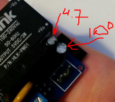
4.7uF CapacitorsSchematics.
c1 100nF
c2 100uF
c3 4.7ufI'm don't have a lot of knowlegde but the 100uF seems te be missing from the BOM. The placement of this part is under the HLK. I have a lot of trouble place the C1 and C2.
I have a ceramic one with number 104 in C2. I thought this is the 100nF. So should it be in C1? But it's so small and nice. And then C2 is missing from the BOM and the only 100uF I have from an other project is big. It realy won't fit under the HLK.
Can some-one give some insight on the BOM, C1 and C2, Ceramic code numbers.
This would realy help me and maybe a few others.Also on my board the holes for the fuse 2 where to small had to drill them out. Second the request for a thermal-fuse. But thanks for this great design.
-
@aproxx Could you clarify the capacitors please? C2 on a post in this thread is 100uF but there are hard to get as ceramics and even the half height ones I have make the arduino stand very high off the board.
Thanks muchly!
@shabba http://nl.aliexpress.com/item/100pcs-lot-Multilayer-ceramic-capacitor-0-1uF-104-50V-100nF-104M/32429917283.html?ws_ab_test=searchweb201556_7_79_78_77_80,searchweb201644_5,searchweb201560_7
you can solder these under the processor board
the 100uF does not have to be a ceramic one...
-
thanks for reply @AWI - The 100nf one does not go under - it is the 100uF one that does. I have a small electrolytic one (it is slightly smaller than the second link you mention) and there is still not enough space - my arduino is too low - I could try and find higher pin stands. I'm sure some ppl will go off and buy all these parts like me so I hope they are aware. Would have been ideal for a SMD really (like the varistor right beside it).
-
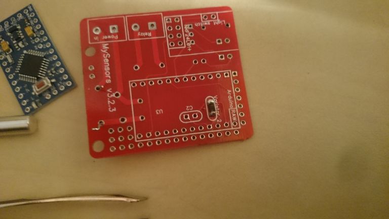
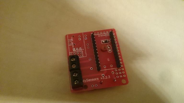
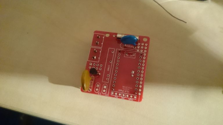
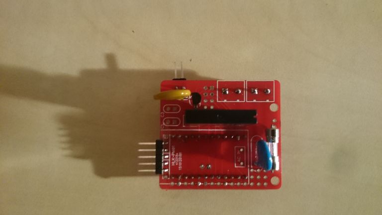
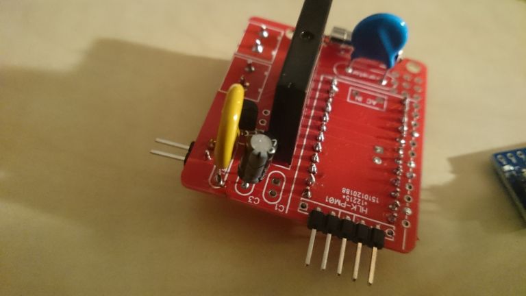
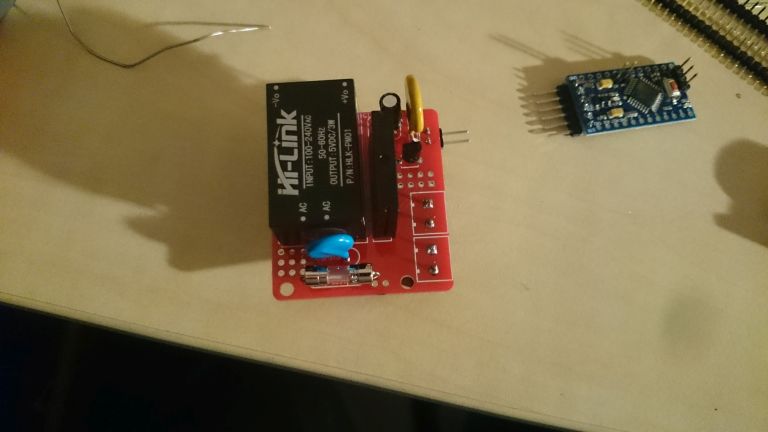
I still have trouble figuring out the C1 and C2. Here are some picture of my build so far.
Not sure all the components are placed correctly.C1 is placed with a small 100nf (104) but BOM in zip say's this is wrong.
As you can see i placed this one, cause the 100uf will not fit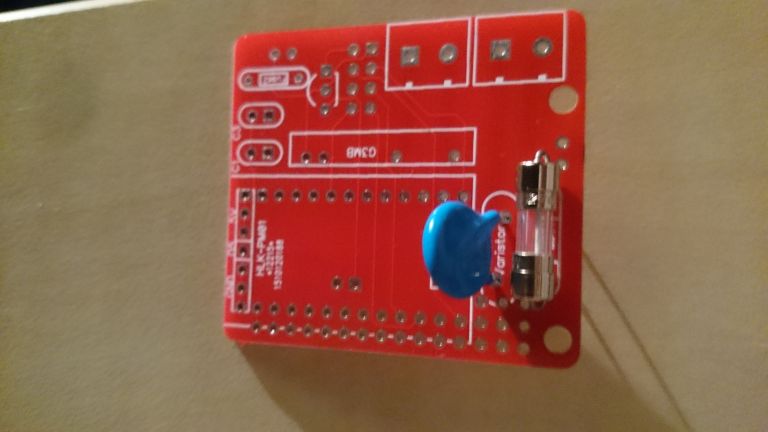
-
I still have trouble figuring out the C1 and C2. Here are some picture of my build so far.
Not sure all the components are placed correctly.C1 is placed with a small 100nf (104) but BOM in zip say's this is wrong.
As you can see i placed this one, cause the 100uf will not fit
-
So the regulator needs swapping about and the BOM cap values are incorrect from post (http://forum.mysensors.org/topic/1540/110v-230v-ac-to-mysensors-pcb-board/37) above that states :::
C1 100nF capacitor
C2 100uF capacitor
C3 4.7uF capacitor?
-
Hmmm. I got the 5.5V DC varistor from another AliExpress seller and I'm a bit puzzled as to why it starts smoking after a few seconds. Tried several of them. The HLK gives a solid 5V output. I'm assuming I got some lower voltage varistors by mistake?
-
So the regulator needs swapping about and the BOM cap values are incorrect from post (http://forum.mysensors.org/topic/1540/110v-230v-ac-to-mysensors-pcb-board/37) above that states :::
C1 100nF capacitor
C2 100uF capacitor
C3 4.7uF capacitor?
-
Hmmm. I got the 5.5V DC varistor from another AliExpress seller and I'm a bit puzzled as to why it starts smoking after a few seconds. Tried several of them. The HLK gives a solid 5V output. I'm assuming I got some lower voltage varistors by mistake?
@bjornhallberg Maybe I've missed reading something, but why use a varistor for 5 Vdc and not a zener diode?
-
@shabba Right... if you look at the schematics
you can see that the two capacitors can be swapped without consequences
-
@bjornhallberg Maybe I've missed reading something, but why use a varistor for 5 Vdc and not a zener diode?
@m26872 You're probably right, I just followed the BOM. I'll see if I can stock up on some diodes from AliExpress for future use.
-
Just a stupid question, the "G3MB-202P DC-AC PCB SSR In 5VDC,Out 240V AC 2A " What happens if I forget and plug something more power-hungry like a toaster or a microwave-owen? does any of the fuses blow or does the relay break ?
-
there is no fuse on the relay switch so I guess either the PCB or the relay will fail.
-
I've seen commercial products with a thermal fuse glued to the switching side of the relay. Maybe that would help some in such situation.
-
Whould a 5.1V zener work?
edit: removed the link to the product so that no one would buy it the specs of it is to tight to be used with HLK.