110v-230v AC to Mysensors PCB board
-
@korttoma Say what...? You measure .4 ohms on your Varistor? I think you found your problem. :angry:
I have only ever used Varistor protection on the primary side, so I've got no experience with low voltage Varistors, but I don't think it should ever read .4.. Should be infinite.
@ServiceXp said:
@korttoma Say what...? You measure .4 ohms on your Varistor? I think you found your problem. :angry:
I have only ever used Varistor protection on the primary side, so I've got no experience with low voltage Varistors, but I don't think it should ever read .4.. Should be infinite.
I how received a new batch from another seller and these varistors show infinite resistance, unfortunately they are 0603 footprint so they are really tiny.
I bet the other seller (Unionup Electronic Mall) just sent me random crap because all of them show 0 resistance at first and then increase to 0.4 ohms, to bad it is too late to open dispute now. Just stay clear of Unionup Electronic Mall in the future.
-
is it the brown or blue varistors that is defective?
Edit: sorry the brown ones are fuses
-
is it the brown or blue varistors that is defective?
Edit: sorry the brown ones are fuses
@Cliff-Karlsson the 5.5V SMD varistors I recieved from Aliexpress seller "Unionup Electronic Mall" do not work for me. Now running my circuit with out it instead.
-
@ServiceXp said:
@korttoma Say what...? You measure .4 ohms on your Varistor? I think you found your problem. :angry:
I have only ever used Varistor protection on the primary side, so I've got no experience with low voltage Varistors, but I don't think it should ever read .4.. Should be infinite.
I how received a new batch from another seller and these varistors show infinite resistance, unfortunately they are 0603 footprint so they are really tiny.
I bet the other seller (Unionup Electronic Mall) just sent me random crap because all of them show 0 resistance at first and then increase to 0.4 ohms, to bad it is too late to open dispute now. Just stay clear of Unionup Electronic Mall in the future.
-
I don't have any ceramic capacitors. Can I replace them with regualr ones?
-
Nevermind the capacitor question I found some ceramic capacitors now. But Is the "BOM" that shows component placement in the beginning of the thread accurate? only the transistor needs to be turned around?
-
@bjornhallberg said:
@m26872 You're probably right, I just followed the BOM. I'll see if I
I think the first post should be edited with the right components. In the doc it says
100nF + 100pF Capacitors 0.02 Euro AliExpress Link
but in the post is says:C2 100uF capacitor
I have a couple of 100uF 16v but I guess that wont work, correct?
-
Sorry for spamming but regarding fuse 2. Can someone post a link to a fuse that works well. I got alot of those brown PTC fuses but the holes in the PCB are too small. I tried drilling them up but then I got no contact so I had to solder a separate separate wire from 5v to the fuse to get any power to the arduino and the rest of the components.
Or has there been a mistake on my PCB with too small holes for fuse 2?
@Cliff-Karlsson the holes for Fuse2 are to smal and this has been mentioned a few times before in this thread. I drilled mine out with a 0.8mm drill and could then use the recommended fuse without any extra wires.
-
Since the 5.5V varistor is not available from the linked AliExpress shop I wonder whether this varistor would work as well?
https://www.conrad.de/de/smd-varistor-we-vs-82537040-4-v-wuerth-elektronik-we-vs-82537040-1-st-1086820.html -
greeted everyone
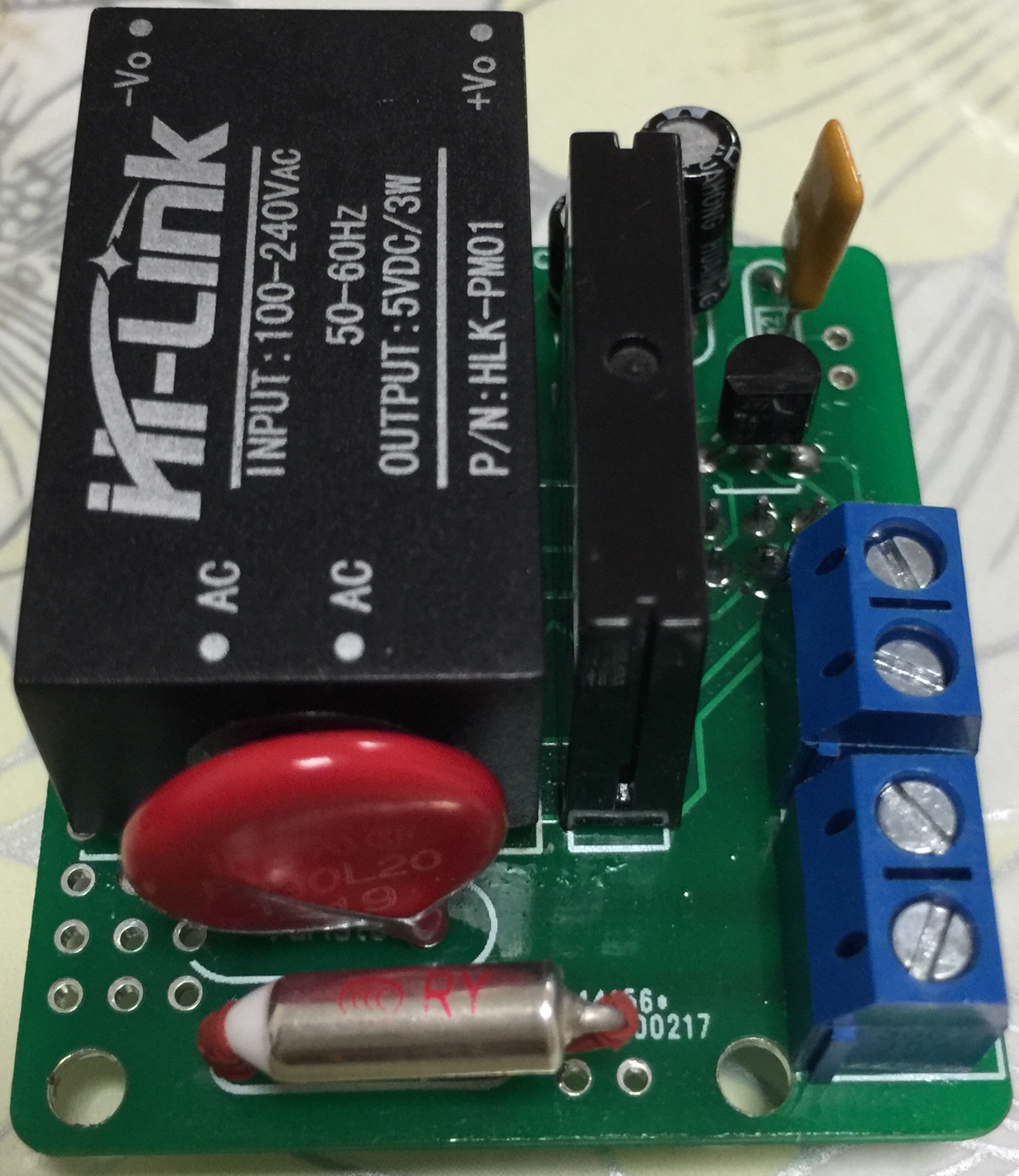
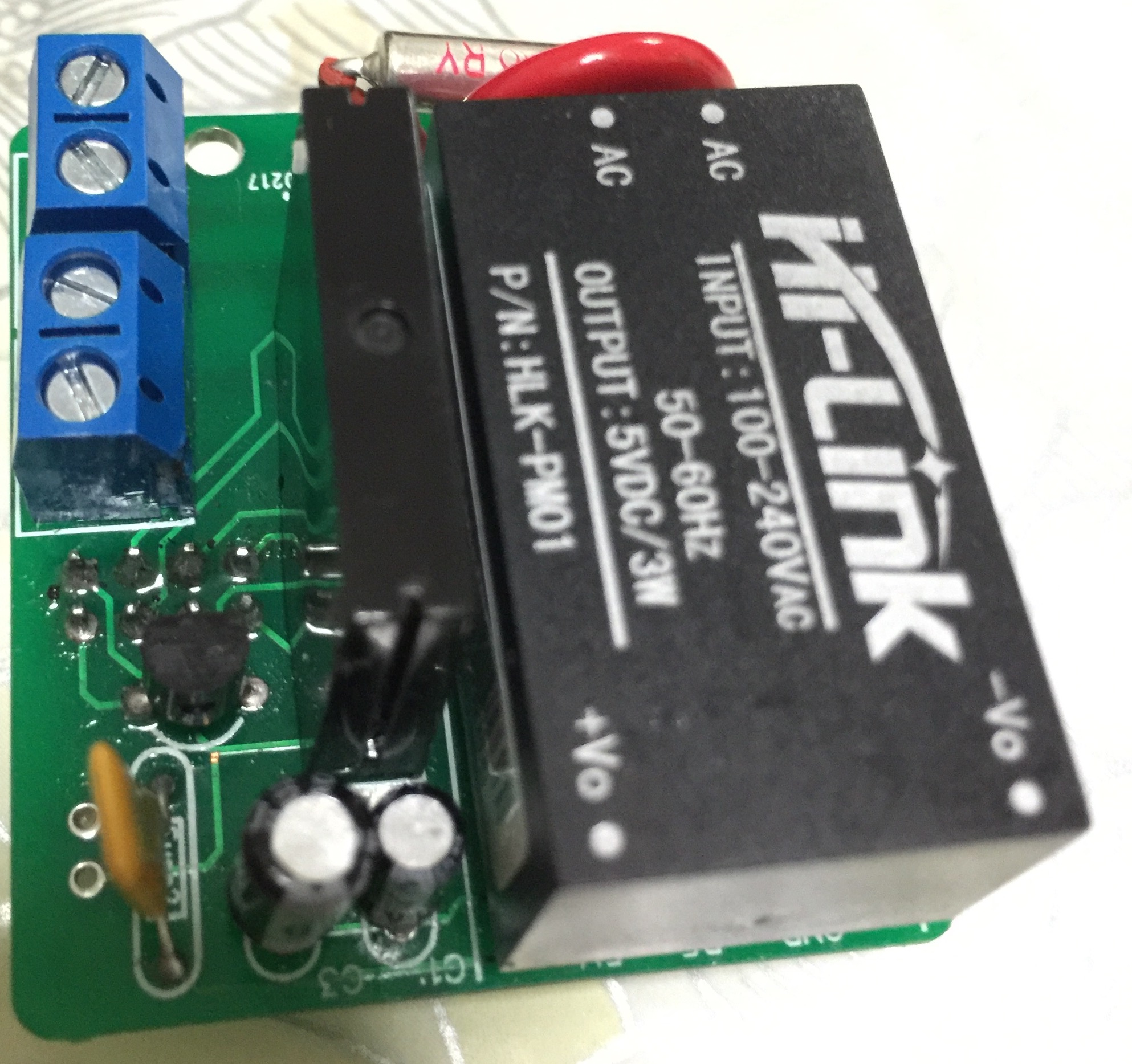
look what concerns island link tests on this HLK-PM01
http://lygte-info.dk/review/Power Mains to 5V 0.6A Hi-Link HLK-PM01 UK.html -
A question about the fuses. The BOM in the Word document links to two 230V fuses, the PTC and slow blow fuse. If I read the schematic correctly one fuse is on the AC side and one is on the DC side. How does a 230V fuse help on the DC side where there should not be more than 5Vdc? Or am I missing something? As I'm quite new to this I'm probably not reading the schematic correctly or missing something :-)
-
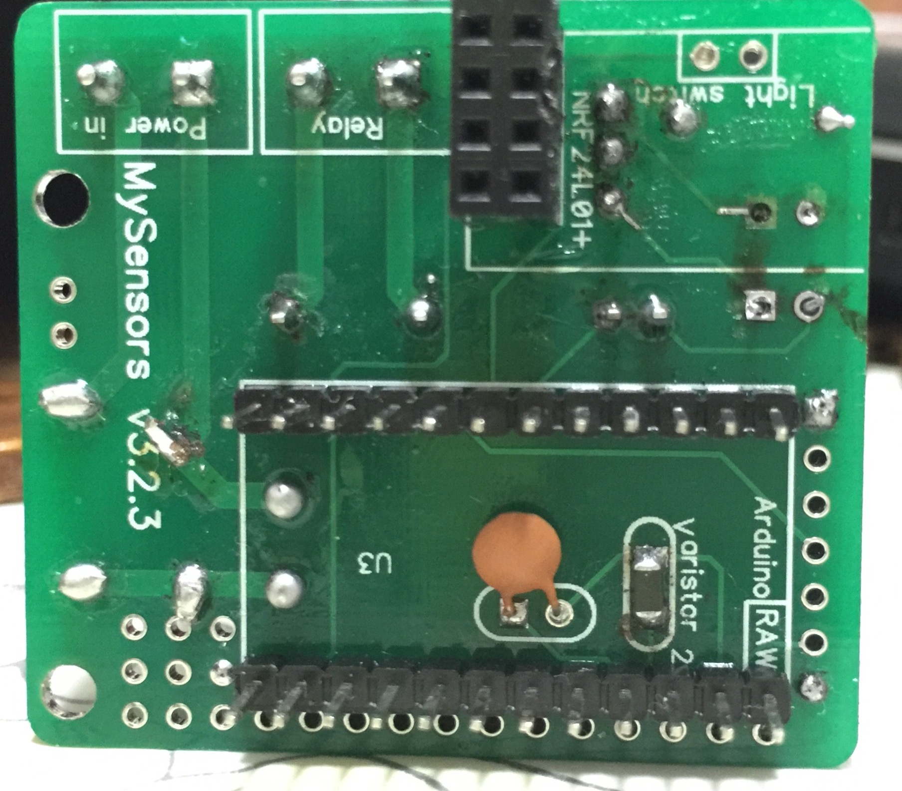
For those who wanted to see some pictures of the board:
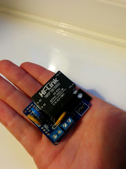
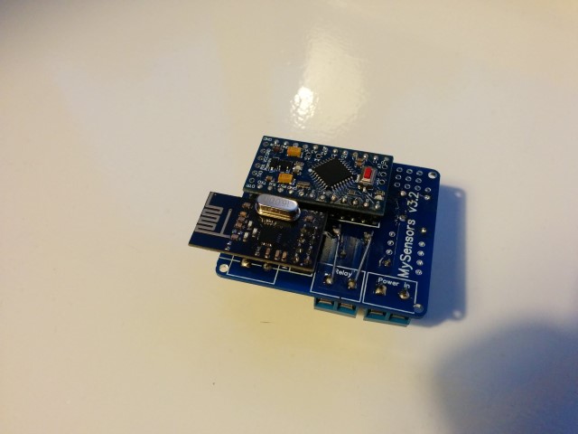
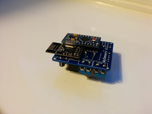
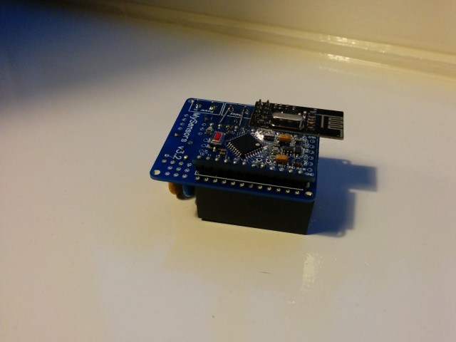
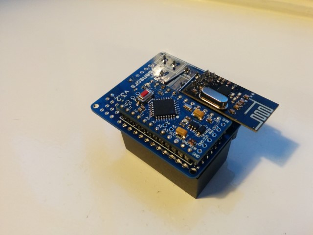
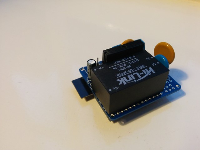
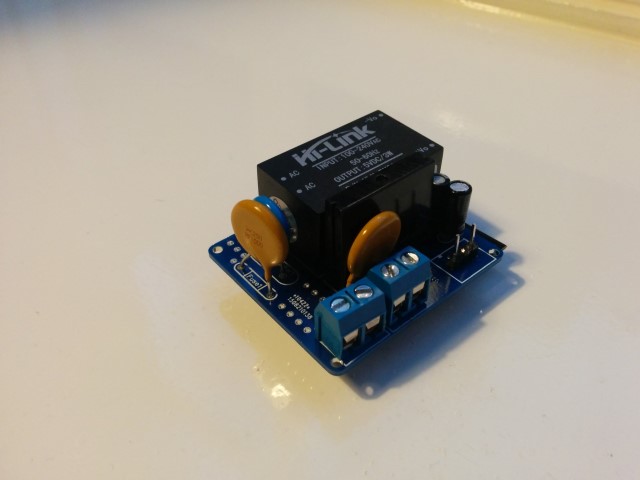
Small notice: These pictures are of a slightly older design. The newer design has a few minor changes like better component placement and a permanent fuse instead of this resettable fuse. But these pictures should at least give you an idea on how everything looks like, and shows how really small it actually is.
Also, I reinforced the traces of the 230v lines, which I absolutely recommend to do! (Although I do recommend to do it slightly more professional than I did on this prototype :))@aproxx said:
For those who wanted to see some pictures of the board:
Small notice: These pictures are of a slightly older design. The newer design has a few minor changes like better component placement and a permanent fuse instead of this resettable fuse. But these pictures should at least give you an idea on how everything looks like, and shows how really small it actually is.
Also, I reinforced the traces of the 230v lines, which I absolutely recommend to do! (Although I do recommend to do it slightly more professional than I did on this prototype :))I really like this design, but it would be even nicer when this fits a ESP8266 :) Maybe the PCB could be even smaller . And it works together with link text .
So is there maybe one of the PCB designer guys who can build /draw / design this 230v to ESP8266 PCB ? -
WOW, REALLY GREAT JOB!
-
Hello everyone,
This is a gr8 project, i am looking forward to make few sensor for my home. As i don't have any experience with electronics and very new to all these terms and components.
I would request anyone of you to, kindly post some pictures of the board with components in place that i can copy and make my boards.
**Specially 3 pin regulator and Capacitors **My first assembled board is not working, it looks like m doing something wrong with either the capacitors or the regulator. I checked my NRF24l01 VCC pin and not getting any voltage at all.
Please help me guys......
Thanks and Regards
Brij -
Hello everyone,
This is a gr8 project, i am looking forward to make few sensor for my home. As i don't have any experience with electronics and very new to all these terms and components.
I would request anyone of you to, kindly post some pictures of the board with components in place that i can copy and make my boards.
**Specially 3 pin regulator and Capacitors **My first assembled board is not working, it looks like m doing something wrong with either the capacitors or the regulator. I checked my NRF24l01 VCC pin and not getting any voltage at all.
Please help me guys......
Thanks and Regards
Brij@Brijesh-Mishra said:
I would request anyone of you to, kindly post some pictures of the board with components in place that i can copy and make my boards.
@the-cosmic-gate has already posted images above.
Perhaps you should post a picture of what you've done?
-
Thanks a lot for your response, this is what i have done so far.
-
Could I ask to the smart PCB builder's / designers to make the same 230v PCB but not using an Arduino but one of the ESP8266 versions , the the board could be even smaller and easier to fix in the wholes