Skip to content
  • MySensors
  • OpenHardware.io
  • Categories
  • Recent
  • Tags
  • Popular
Skins
  • Light
  • Brite
  • Cerulean
  • Cosmo
  • Flatly
  • Journal
  • Litera
  • Lumen
  • Lux
  • Materia
  • Minty
  • Morph
  • Pulse
  • Sandstone
  • Simplex
  • Sketchy
  • Spacelab
  • United
  • Yeti
  • Zephyr
  • Dark
  • Cyborg
  • Darkly
  • Quartz
  • Slate
  • Solar
  • Superhero
  • Vapor

  • Default (No Skin)
  • No Skin
Collapse
Brand Logo
  1. Home
  2. Hardware
  3. 110v-230v AC to Mysensors PCB board

110v-230v AC to Mysensors PCB board

Scheduled Pinned Locked Moved Hardware
269 Posts 63 Posters 270.9k Views 68 Watching
  • Oldest to Newest
  • Newest to Oldest
  • Most Votes
Reply
  • Reply as topic
Log in to reply
This topic has been deleted. Only users with topic management privileges can see it.
  • V Offline
    V Offline
    vil1driver
    wrote on last edited by
    #237

    maybe a fuse to protect relay output.. ?
    and plz add a second switch, to control an other node or anything..

    1 Reply Last reply
    0
    • Sefi NinioS Offline
      Sefi NinioS Offline
      Sefi Ninio
      wrote on last edited by
      #238

      So basically, I should duplicate the current circuit for the new relay...

      1 Reply Last reply
      0
      • J Offline
        J Offline
        Jan Gatzke
        wrote on last edited by
        #239

        I am facing a little problem with the fuses. I am using these:

        230V AC: http://de.aliexpress.com/item/TRF250-300U-line-resettable-fuses-0-3A-300MA-250V-Tyco/32368739339.html?detailNewVersion=2

        5V DC: http://www.ebay.de/itm/321697892220?_trksid=p2057872.m2749.l2649&ssPageName=STRK%3AMEBIDX%3AIT

        When I connect the pcb to power the LED on the Arduino flashes and then the 500 mA Fuse in the 5V circuit dies. I am now using the 300 mA resetable Fuse for the 5V part as well, which seems to work without problems. How can it be, that the 500 mA fuse dies and the 300 mA fuse does not?

        1 Reply Last reply
        0
        • TmasterT Offline
          TmasterT Offline
          Tmaster
          wrote on last edited by Tmaster
          #240

          Jan Gatzke; chinese brand electronics... who knows what can happens....

          i ordered all stuff needed to make my pcb with maximun 4x4cms to use inside wall switches (like zwave fibaro modules). i will try to reduce that board by not using connectors and solder the cables directly etc..

          Something that i don't know is why use a varistor and fuse on secundary??? arduino already have an polyfuse PPTC Resetable fuse, and someting bad that happens with nrf24 will burn the 3.3V regulator.. its that varistor and fuse realy needed?

          i'm a arduino fan .Even sometimes don't undestanding how to use it :P

          1 Reply Last reply
          0
          • A aproxx

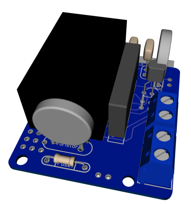
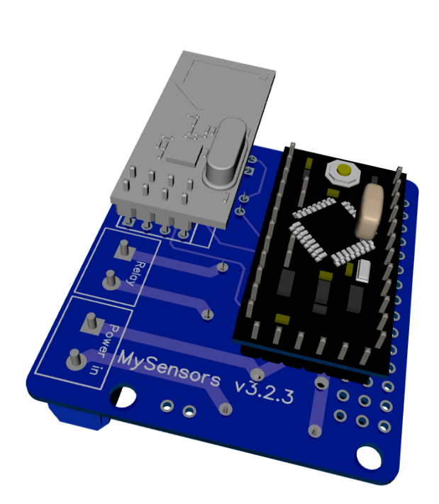
            As promised, I've got an update for this project. The board has been tested in the past week, and everything is working as expected. Compared to the previous board I've posted, I have updated the following:
            • Solder pads of LE33CZ have been placed a little wider apart to avoid short circuit while soldering.
            • Solder pads of the resettable fuse (Fuse2) has been placed closer together to better fit the fuses of the BOM.
            • Moved the NRF24L01 connector a bit away from the solid state relay. Should make it easier to solder.
            • Moved Fuse2 to another location on the board, away from the 230v circuit.

            Some 3D pictures (Top and bottom):
            Top.png
            Bottom.png

            Anyone who is interested can order the PCB HERE

            Some documentation, and all gerber / DipTrace files (in case you would like to make some modifications) can be found here: MySensors board v3.2.3.zip.

            S Offline
            S Offline
            scropion86
            wrote on last edited by
            #241

            @aproxx hello. can i know how you rendered your PCB layout to 3D , if any tutorial it can guide me
            to achieve that .

            thanks

            1 Reply Last reply
            0
            • A Offline
              A Offline
              aproxx
              Hero Member
              wrote on last edited by
              #242

              Wow, this thread has been really active in the past few months! I'm sorry for my absence, but I kind of got dragged into other projects.. :)

              A new version of the board will be shared soon! Compared to the current board following changes have been made:

              • A second solid state relay has been added. This 2nd relay is optional, so if only 1 device needs to be controlled just 1 relay needs to be installed and everything will still work fine.
              • The board size has been increased just a little bit to fit this 2nd relay. Size is still 5x5cm only.
              • Some components have been moved in order to make it easier to solder them (This was a bit tricky on version 3.2.3 because some components were really close to each other).
              • Traces between the relays and the connectors are now 'open air'. So there is no mask on top of the traces. This way it is possible to reinforce the traces. By doing this it shouldn't be any problem to connect a 2A load to the board.
              • A temperature cut-off has been added to the board.
              • The varistor for the low voltage circuit has been removed because it's not really needed anymore with all the extra security measures on the high voltage side of the board.

              Currently this board is still on it's way from China, but as soon as I've received this board I'll share all the documentation and everything else which is needed on this forum! This will probably happen in 3-5 weeks from now, so stay tuned! ;)

              TmasterT J 2 Replies Last reply
              4
              • hekH Offline
                hekH Offline
                hek
                Admin
                wrote on last edited by
                #243

                Great @approx, please consider to create it as new project over at openhardware.io, much easier to keep track of things (and a forum thread will be created automatically).

                1 Reply Last reply
                0
                • A Offline
                  A Offline
                  aproxx
                  Hero Member
                  wrote on last edited by
                  #244

                  @hek That sounds as a great idea. I'll share it on OpenHardware as soon as I have confirmed that everything works as expected!

                  1 Reply Last reply
                  0
                  • A aproxx

                    Wow, this thread has been really active in the past few months! I'm sorry for my absence, but I kind of got dragged into other projects.. :)

                    A new version of the board will be shared soon! Compared to the current board following changes have been made:

                    • A second solid state relay has been added. This 2nd relay is optional, so if only 1 device needs to be controlled just 1 relay needs to be installed and everything will still work fine.
                    • The board size has been increased just a little bit to fit this 2nd relay. Size is still 5x5cm only.
                    • Some components have been moved in order to make it easier to solder them (This was a bit tricky on version 3.2.3 because some components were really close to each other).
                    • Traces between the relays and the connectors are now 'open air'. So there is no mask on top of the traces. This way it is possible to reinforce the traces. By doing this it shouldn't be any problem to connect a 2A load to the board.
                    • A temperature cut-off has been added to the board.
                    • The varistor for the low voltage circuit has been removed because it's not really needed anymore with all the extra security measures on the high voltage side of the board.

                    Currently this board is still on it's way from China, but as soon as I've received this board I'll share all the documentation and everything else which is needed on this forum! This will probably happen in 3-5 weeks from now, so stay tuned! ;)

                    TmasterT Offline
                    TmasterT Offline
                    Tmaster
                    wrote on last edited by
                    #245

                    @aproxx said:

                    • The varistor for the low voltage circuit has been removed because it's not really needed anymore with all the extra security measures on the high voltage side of the board.

                    exacly what i was talking about!:+1:

                    i'm a arduino fan .Even sometimes don't undestanding how to use it :P

                    1 Reply Last reply
                    0
                    • V Offline
                      V Offline
                      vil1driver
                      wrote on last edited by vil1driver
                      #246

                      bad news :-/ then why have you fuse at home ? 400 000 V has security measures, why add more security ? it's juste our life, childs life !!
                      do you know what is a "security transformer" ? the hlk-pm01 isn't one.

                      A 1 Reply Last reply
                      0
                      • V vil1driver

                        bad news :-/ then why have you fuse at home ? 400 000 V has security measures, why add more security ? it's juste our life, childs life !!
                        do you know what is a "security transformer" ? the hlk-pm01 isn't one.

                        A Offline
                        A Offline
                        aproxx
                        Hero Member
                        wrote on last edited by aproxx
                        #247

                        @vil1driver said:

                        bad news :-/ then why have you fuse at home ? 400 000 V has security measures, why add more security ? it's juste our life, childs life !!
                        do you know what is a "security transformer" ? the hlk-pm01 isn't one.

                        It's not that I think that security isn't important, but I believe that no security on the low voltage side is safer than having a false sense of security. As I've read above, lots of the low voltage fuses were not reliable. And that's one reason I dropped it in the newer design.

                        All that aside: I never ever EVER intend to mount these boards on locations people can reach (unless they intend to). Everything is placed safely behind a light switch or in a completely closed plastic box. The only thing that COULD be touched is the wires to the switch itself (And even those will be out of reach if the lid of the switch is on). But since these switches are only connected to ground and a digital input, those wires don't do any harm.

                        But yes, I do know what a 'security transformer' is. And no, I completely agree the HLK-PM01 itself isn't a secure transformer. But considering the price, the added fuses and temp cutoffs, and the plan to mount these in a safe location, I believe the HLK-PM01 does the job well. ;)

                        1 Reply Last reply
                        0
                        • V Offline
                          V Offline
                          vil1driver
                          wrote on last edited by
                          #248

                          thanks for your answer,

                          1 Reply Last reply
                          0
                          • TmasterT Offline
                            TmasterT Offline
                            Tmaster
                            wrote on last edited by
                            #249

                            Secure? ... A varistor and a 8v fuse on secundary line! ...
                            Never touch devices when powered to mains. A simple light bulb that you can touch on metal part, a tablet charger that can blow up... just don't touch the module and put it inside wall (not wood) or circuit case.

                            alt text

                            i'm a arduino fan .Even sometimes don't undestanding how to use it :P

                            1 Reply Last reply
                            0
                            • A aproxx

                              Wow, this thread has been really active in the past few months! I'm sorry for my absence, but I kind of got dragged into other projects.. :)

                              A new version of the board will be shared soon! Compared to the current board following changes have been made:

                              • A second solid state relay has been added. This 2nd relay is optional, so if only 1 device needs to be controlled just 1 relay needs to be installed and everything will still work fine.
                              • The board size has been increased just a little bit to fit this 2nd relay. Size is still 5x5cm only.
                              • Some components have been moved in order to make it easier to solder them (This was a bit tricky on version 3.2.3 because some components were really close to each other).
                              • Traces between the relays and the connectors are now 'open air'. So there is no mask on top of the traces. This way it is possible to reinforce the traces. By doing this it shouldn't be any problem to connect a 2A load to the board.
                              • A temperature cut-off has been added to the board.
                              • The varistor for the low voltage circuit has been removed because it's not really needed anymore with all the extra security measures on the high voltage side of the board.

                              Currently this board is still on it's way from China, but as soon as I've received this board I'll share all the documentation and everything else which is needed on this forum! This will probably happen in 3-5 weeks from now, so stay tuned! ;)

                              J Offline
                              J Offline
                              jemish
                              wrote on last edited by
                              #250

                              @aproxx
                              what is your progress for new version of two relay switch board?

                              A 1 Reply Last reply
                              0
                              • J jemish

                                @aproxx
                                what is your progress for new version of two relay switch board?

                                A Offline
                                A Offline
                                aproxx
                                Hero Member
                                wrote on last edited by
                                #251

                                @jemish The boards were sent to me from China 5 days ago. I don't have a tracking number available, but usually it takes between 3 and 5 weeks before they reach me (Belgium). I already have all the necessary components, so within a week after I received the boards I'll provide this topic with an update.

                                1 Reply Last reply
                                0
                                • S Offline
                                  S Offline
                                  shabba
                                  wrote on last edited by
                                  #252

                                  Its been a long time since I built one of these but I recall there were some gotchas. I have a bunch of version 2.2.3. Besides the silk screen showing wrong orientation for the regulator what else was there?
                                  Perhaps @aproxx could update first post?
                                  Thanks!

                                  1 Reply Last reply
                                  0
                                  • A Offline
                                    A Offline
                                    aproxx
                                    Hero Member
                                    wrote on last edited by
                                    #253

                                    Hi @shabba.
                                    I assume you mean version 3.2.3 of the board?
                                    Besides the silkscreen of the LE33 being the other way around, there are a few other things to keep in mind:

                                    • The drill holes of the fuse/varistor on the 230v side might be a bit small. So it is advised to either make those holes a bit bigger, or to make the legs of the fuse/varistor a bit thinner using some sandpaper.
                                    • Make sure to solder the components in the correct order (As mentioned in the Word document, which is part of the ZIP file of the opening post).

                                    I'll update the first post of this topic in a few weeks, which includes the newer board version that fixes all the problems as stated above.

                                    S 1 Reply Last reply
                                    2
                                    • A aproxx

                                      Hi @shabba.
                                      I assume you mean version 3.2.3 of the board?
                                      Besides the silkscreen of the LE33 being the other way around, there are a few other things to keep in mind:

                                      • The drill holes of the fuse/varistor on the 230v side might be a bit small. So it is advised to either make those holes a bit bigger, or to make the legs of the fuse/varistor a bit thinner using some sandpaper.
                                      • Make sure to solder the components in the correct order (As mentioned in the Word document, which is part of the ZIP file of the opening post).

                                      I'll update the first post of this topic in a few weeks, which includes the newer board version that fixes all the problems as stated above.

                                      S Offline
                                      S Offline
                                      shabba
                                      wrote on last edited by
                                      #254

                                      @aproxx Thanks - It was a while since I did my last one so wanted to be clear. Looking forward to seeing new one. Great work - appreciated!

                                      1 Reply Last reply
                                      0
                                      • kurniawan77K Offline
                                        kurniawan77K Offline
                                        kurniawan77
                                        wrote on last edited by
                                        #255

                                        Ordered the boards... Can't wait!

                                        Ever thought of implementing ACS 712 ?

                                        1 Reply Last reply
                                        0
                                        • J Offline
                                          J Offline
                                          jemish
                                          wrote on last edited by
                                          #256

                                          I waiting for new version of two relay switch board.

                                          A 1 Reply Last reply
                                          0
                                          Reply
                                          • Reply as topic
                                          Log in to reply
                                          • Oldest to Newest
                                          • Newest to Oldest
                                          • Most Votes


                                          20

                                          Online

                                          11.7k

                                          Users

                                          11.2k

                                          Topics

                                          113.0k

                                          Posts


                                          Copyright 2019 TBD   |   Forum Guidelines   |   Privacy Policy   |   Terms of Service
                                          • Login

                                          • Don't have an account? Register

                                          • Login or register to search.
                                          • First post
                                            Last post
                                          0
                                          • MySensors
                                          • OpenHardware.io
                                          • Categories
                                          • Recent
                                          • Tags
                                          • Popular