110v-230v AC to Mysensors PCB board
-
@aproxx will the second relay be opt-in?
I mean, will the board function normally with only one relay?@Sefi-Ninio
Yes, it will be perfectly possible to just install 1 relay on the board and it will still work fine.
More news in the next few days! ;) -
The latest version of this board is available here!
Because of the large number of request a second (optional) solid state relay has been added to the board. Enjoy! -
@jemish
It's on the middle of the board on the top side. 4 pins are present to use as switch inputs. 2 pins are ground, and then pin 4 and 7 are available as well.
By closing the connection between pin 4 and ground you will switch te status of relay 1. When closing the connection between ground and pin 7 you'll switch the status of relay 2. -
Hi all,
**UPDATE April 17 2016 **
The latest version of this board is available HERE.After spending a few months on this forum and a few prototypes later, I decided I wanted to build a small but cheap PCB which could be placed in either the wall behind the light switch, or above the lamp.
Besides the boards I've seen on this forum, I wanted these boards to contain a module to go from 230v AC to 5/3.3v DC in order to power an Arduino nano and the NRF module. I eventually ended up with a PCB which is about 4 by 4.5cm. So with all components attached I'm hoping to get in stuffed in a 5x5x3cm plastic printed case.
Modules which I've used to power the board:
[http://www.aliexpress.com/item/5-pcs-HLK-PM01-AC-DC-220V-to-5V-Step-Down-Power-Supply-Module-Intelligent-Household/32319202093.html?spm=2114.32010308.4.19.8oKfZgUPDATE: 2015/09/18
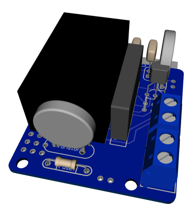
As promised, I've got an update for this project. The board has been tested in the past week, and everything is working as expected. Compared to the previous board I've posted, I have updated the following:
• Solder pads of LE33CZ have been placed a little wider apart to avoid short circuit while soldering.
• Solder pads of the resettable fuse (Fuse2) has been placed closer together to better fit the fuses of the BOM.
• Moved the NRF24L01 connector a bit away from the solid state relay. Should make it easier to solder.
• Moved Fuse2 to another location on the board, away from the 230v circuit.Some 3D pictures (Top and bottom):
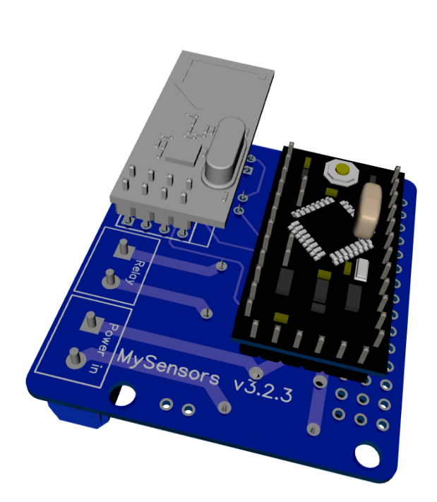
Anyone who is interested can order the PCB HERE
Some documentation, complete list of required components and all gerber / DipTrace files (in case you would like to make some modifications) can be found here: MySensors board v3.2.3.zip.
@aproxx I have a few left-over boards from the earlier release - where the holes for fuse2 were smaller than required (PTC Resettable Fuses 250V 1A TRF250-1000 PPTC Polymeric PTC PolySwitch). I wanted to use up the remaining boards, and wondering if the following fuse could be a substitute (USA-based, leads are smaller diameter and would fit the holes) - MF-R110 FUSE PTC RESETTABLE 1.10A HOLD MF-R110 110 MF.
Thanks for your guidance.
-
-
@Fat-Fly these tiny boards have really bad isolation and are dangerous tu use.
And did you have a look at this 1-diode "rectifier" ? The ripple is probably awful and the result will affect the quality of the radio transmission.
Saving 0.5$ compared to an HLK is really not worth it ! -
@bruno tanke you, very good.
I share it in facebook.