Skip to content
  • MySensors
  • OpenHardware.io
  • Categories
  • Recent
  • Tags
  • Popular
Skins
  • Light
  • Brite
  • Cerulean
  • Cosmo
  • Flatly
  • Journal
  • Litera
  • Lumen
  • Lux
  • Materia
  • Minty
  • Morph
  • Pulse
  • Sandstone
  • Simplex
  • Sketchy
  • Spacelab
  • United
  • Yeti
  • Zephyr
  • Dark
  • Cyborg
  • Darkly
  • Quartz
  • Slate
  • Solar
  • Superhero
  • Vapor

  • Default (No Skin)
  • No Skin
Collapse
Brand Logo
  1. Home
  2. Hardware
  3. 110v-230v AC to Mysensors PCB board

110v-230v AC to Mysensors PCB board

Scheduled Pinned Locked Moved Hardware
269 Posts 63 Posters 270.9k Views 68 Watching
  • Oldest to Newest
  • Newest to Oldest
  • Most Votes
Reply
  • Reply as topic
Log in to reply
This topic has been deleted. Only users with topic management privileges can see it.
  • M Offline
    M Offline
    mvdarend
    wrote on last edited by
    #73

    Very nice. :thumbsup: I ordered 10 boards on Saturday, can't wait for them to arrive.

    1 Reply Last reply
    0
    • A aproxx

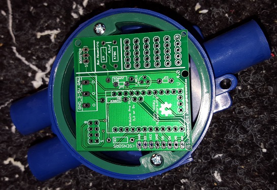
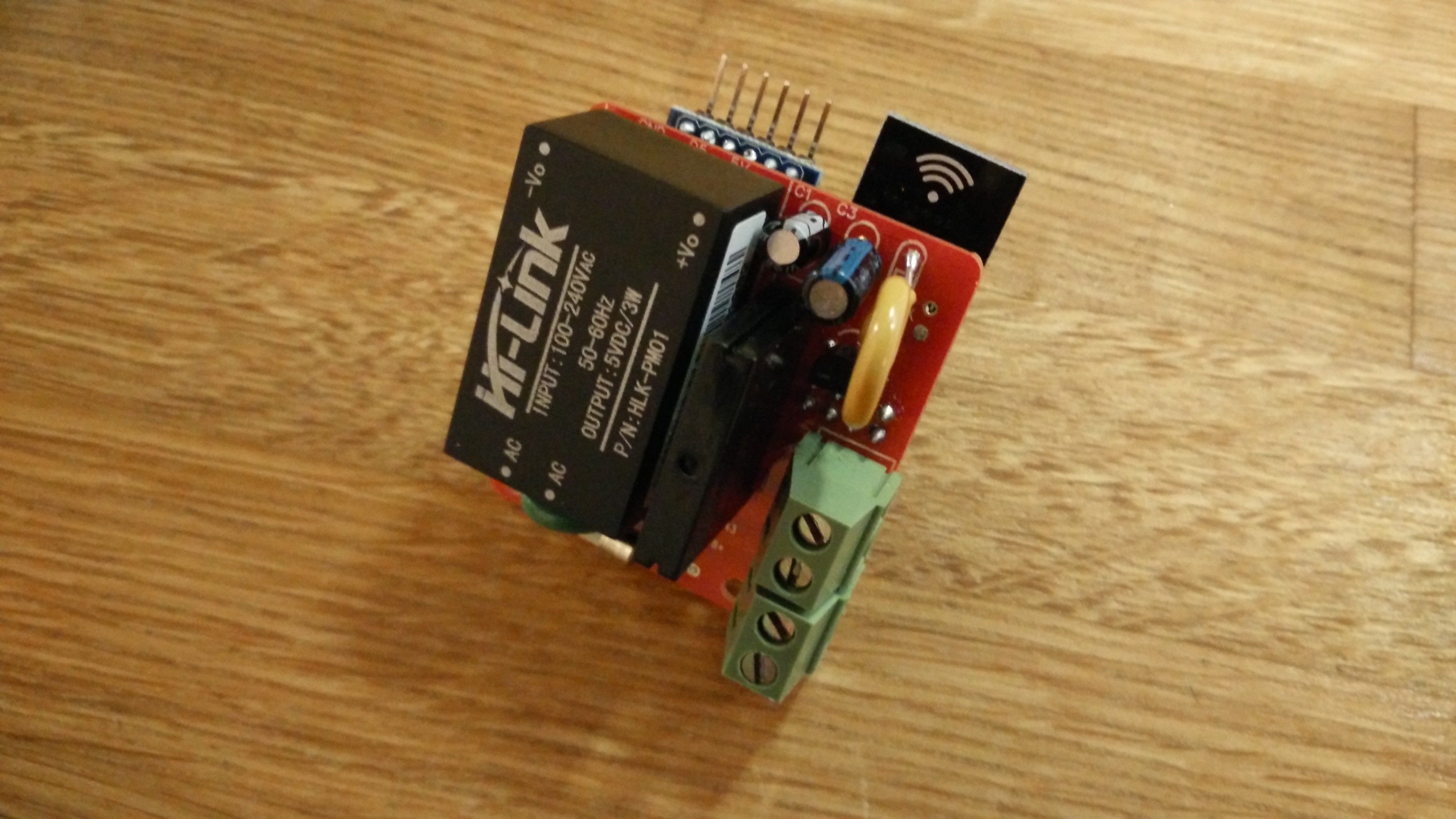
      For those who wanted to see some pictures of the board:
      IMG_20150921_194059 (Small).jpg IMG_20150921_194039 (Small).jpg IMG_20150921_194035 (Small).jpg IMG_20150921_194023 (Small).jpg IMG_20150921_192748 (Small).jpg IMG_20150921_192737 (Small).jpg IMG_20150921_192728 (Small).jpg

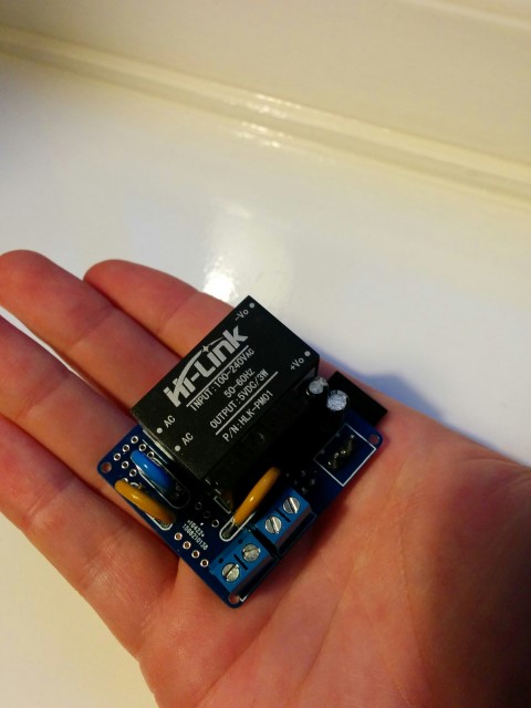
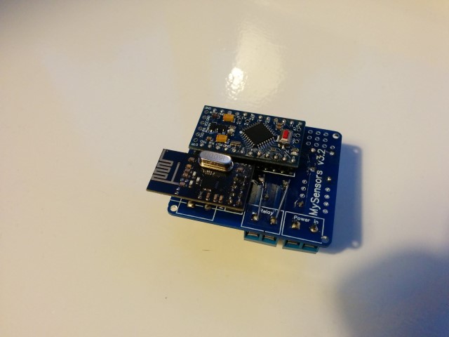
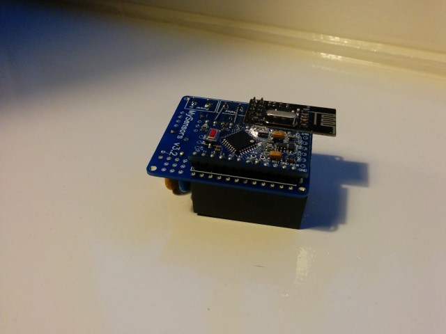
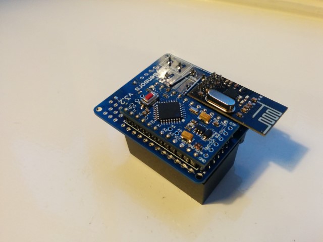
      Small notice: These pictures are of a slightly older design. The newer design has a few minor changes like better component placement and a permanent fuse instead of this resettable fuse. But these pictures should at least give you an idea on how everything looks like, and shows how really small it actually is.
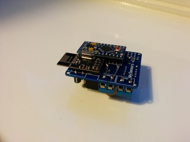
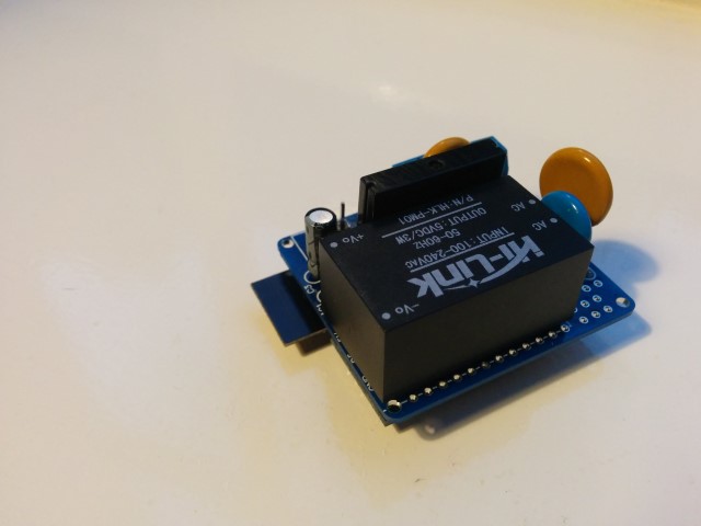
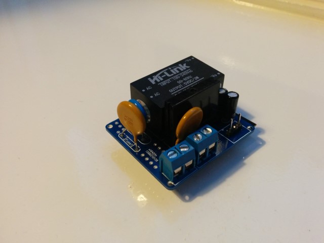
      Also, I reinforced the traces of the 230v lines, which I absolutely recommend to do! (Although I do recommend to do it slightly more professional than I did on this prototype :))

      AWIA Offline
      AWIA Offline
      AWI
      Hero Member
      wrote on last edited by
      #74

      @aproxx Looks cleaner than the 3D view :clap:

      A 1 Reply Last reply
      0
      • AWIA AWI

        @aproxx Looks cleaner than the 3D view :clap:

        A Offline
        A Offline
        aproxx
        Hero Member
        wrote on last edited by
        #75

        @AWI Thanks for the kind words! I did my best on the soldering part, but the reinforcement of the 230v circuit could have done a bit better in my opinion. :) Next time I would use an isolated wire to reinforce the 230v traces, but for a prototype build this was sufficient.

        M 1 Reply Last reply
        0
        • J Offline
          J Offline
          jemish
          wrote on last edited by
          #76

          nice job....very nice....

          1 Reply Last reply
          0
          • J Offline
            J Offline
            Jan Gatzke
            wrote on last edited by
            #77

            Nice job. Why do you need to bridge the 230V lines? Can't you just make the traces bigger? Is it really needed? The relay can only switch 2A. So the traces have to survive 2A, too. You can easily calculate the required traces with tools like this: http://circuitcalculator.com/wordpress/2006/01/31/pcb-trace-width-calculator/

            A 1 Reply Last reply
            0
            • J Jan Gatzke

              Nice job. Why do you need to bridge the 230V lines? Can't you just make the traces bigger? Is it really needed? The relay can only switch 2A. So the traces have to survive 2A, too. You can easily calculate the required traces with tools like this: http://circuitcalculator.com/wordpress/2006/01/31/pcb-trace-width-calculator/

              A Offline
              A Offline
              aproxx
              Hero Member
              wrote on last edited by
              #78

              @Jan-Gatzke I've used a similar calculator before and according to these calculation it isn't mandatory.

              • Dirtypcbs.com claims to use 1oz/ft2 copper thickness (which seems to be 0.035mm).
              • The traces between the solid state relay and connectors are all 2mm wide.
              • Distance between the solid state relay and the connector on the edge is less than 20mm.

              That would lead to the following calculations:
              Schermafdruk 2015-09-22 13.35.55.png

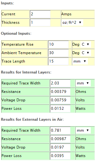
              So you are right that it isn't mandatory to reinforce these traces. However, to be on the safe side I'm still planning to reinforce them. I know, it probably isn't necessary but it doesn't hurt putting this extra effort in, just to be completely safe. :)

              1 Reply Last reply
              0
              • J Offline
                J Offline
                Jan Gatzke
                wrote on last edited by
                #79

                Keep in mind, that you do not want to run the relay at 2A for a longer period of time. 2A at 230V means 460 W power consumption. Most devices / lights will consume less. So hopefully this will never be a problem.

                Again, great job. I will definitely order some of the pcbs, too.

                What about the other parts? Do you have some kind of link collection for Ebay/Ali? This would make it even easier to build the device.

                A 1 Reply Last reply
                0
                • J Jan Gatzke

                  Keep in mind, that you do not want to run the relay at 2A for a longer period of time. 2A at 230V means 460 W power consumption. Most devices / lights will consume less. So hopefully this will never be a problem.

                  Again, great job. I will definitely order some of the pcbs, too.

                  What about the other parts? Do you have some kind of link collection for Ebay/Ali? This would make it even easier to build the device.

                  A Offline
                  A Offline
                  aproxx
                  Hero Member
                  wrote on last edited by
                  #80

                  @Jan-Gatzke Indeed, most of my lights only consume like 10% of the maximum rated power, so I should be on the safe side for sure.

                  I have attached a ZIP file which contains all required information in one of my previous posts (HERE). That one contains a Word document with all components and an AliExpress/Ebay link.

                  I'll try and see if I can update the first post of this topic as well to include all important information.

                  1 Reply Last reply
                  0
                  • J Offline
                    J Offline
                    Jan Gatzke
                    wrote on last edited by
                    #81

                    Ok, lazy me didn't have a look at the zip. Tanks for the hint. :)

                    1 Reply Last reply
                    0
                    • petewillP Offline
                      petewillP Offline
                      petewill
                      Admin
                      wrote on last edited by
                      #82

                      @aproxx This looks very cool! I am curious what (if any) heat sink will be used with the solid state relay? I have never used a solid state relay but I have been reading about them and it seems that most are used with a heat sink. Maybe it depends on the amperage that will be switched though. Thanks!

                      My "How To" home automation video channel: https://www.youtube.com/channel/UCq_Evyh5PQALx4m4CQuxqkA

                      1 Reply Last reply
                      0
                      • bjornhallbergB Offline
                        bjornhallbergB Offline
                        bjornhallberg
                        Hero Member
                        wrote on last edited by
                        #83

                        The SSR has an integrated heat sink according to the specs. Don't know if this is a knockoff and follows the same standard of quality though. Given the low A rating, and the fact that most of us will be switching a 10-20W worth of lights, I think it will be fine.

                        I noticed the ceramic "Slow Blow Fuse (250v 0.3A)" was out of stock on Ebay. As was the 0.2A version. Someone is stocking up :-) Would it have to be a ceramic fuse?

                        petewillP DrJeffD 2 Replies Last reply
                        0
                        • bjornhallbergB bjornhallberg

                          The SSR has an integrated heat sink according to the specs. Don't know if this is a knockoff and follows the same standard of quality though. Given the low A rating, and the fact that most of us will be switching a 10-20W worth of lights, I think it will be fine.

                          I noticed the ceramic "Slow Blow Fuse (250v 0.3A)" was out of stock on Ebay. As was the 0.2A version. Someone is stocking up :-) Would it have to be a ceramic fuse?

                          petewillP Offline
                          petewillP Offline
                          petewill
                          Admin
                          wrote on last edited by
                          #84

                          @bjornhallberg Thanks. I still have some reading to do... :)

                          My "How To" home automation video channel: https://www.youtube.com/channel/UCq_Evyh5PQALx4m4CQuxqkA

                          1 Reply Last reply
                          0
                          • bjornhallbergB bjornhallberg

                            The SSR has an integrated heat sink according to the specs. Don't know if this is a knockoff and follows the same standard of quality though. Given the low A rating, and the fact that most of us will be switching a 10-20W worth of lights, I think it will be fine.

                            I noticed the ceramic "Slow Blow Fuse (250v 0.3A)" was out of stock on Ebay. As was the 0.2A version. Someone is stocking up :-) Would it have to be a ceramic fuse?

                            DrJeffD Offline
                            DrJeffD Offline
                            DrJeff
                            wrote on last edited by
                            #85

                            @bjornhallberg said:

                            was out of stock on Ebay. As was the 0.2A version. Someone is stocking up

                            :pensive: oops! You wanted some?

                            just kidding, let me check I have a line on parts I will see if they have some.

                            bjornhallbergB 1 Reply Last reply
                            0
                            • DrJeffD DrJeff

                              @bjornhallberg said:

                              was out of stock on Ebay. As was the 0.2A version. Someone is stocking up

                              :pensive: oops! You wanted some?

                              just kidding, let me check I have a line on parts I will see if they have some.

                              bjornhallbergB Offline
                              bjornhallbergB Offline
                              bjornhallberg
                              Hero Member
                              wrote on last edited by
                              #86

                              @DrJeff I actually bought the 0.2A version myself before it was gone :-) But I was surprised to find how hard it was to find axial ceramic fuses of the right size or at the right price. Maybe we could find some sort of small fuse holder instead?

                              DrJeffD 1 Reply Last reply
                              0
                              • bjornhallbergB bjornhallberg

                                @DrJeff I actually bought the 0.2A version myself before it was gone :-) But I was surprised to find how hard it was to find axial ceramic fuses of the right size or at the right price. Maybe we could find some sort of small fuse holder instead?

                                DrJeffD Offline
                                DrJeffD Offline
                                DrJeff
                                wrote on last edited by
                                #87

                                @bjornhallberg said:

                                Maybe we could find some sort of small fuse holder instead?

                                I know its probably not the best thing to do but I have just soldered on leads, bare wire. I just tin the metal first and scuff it a little. I have done the same thing to batteries with no ill effect.The key is get in and off quickly!

                                1 Reply Last reply
                                0
                                • A aproxx

                                  @AWI Thanks for the kind words! I did my best on the soldering part, but the reinforcement of the 230v circuit could have done a bit better in my opinion. :) Next time I would use an isolated wire to reinforce the 230v traces, but for a prototype build this was sufficient.

                                  M Offline
                                  M Offline
                                  mvdarend
                                  wrote on last edited by
                                  #88

                                  @aproxx I'm hoping to receive the boards soon (they were sent almost two weeks ago) and have one question for you.

                                  I've had a quick look at your example code in the Word document but I'm not familiar with Arduino Debouncing. My question is what kind of switch is the best to use, a standard On/Off switch or a Pulse switch?

                                  1 Reply Last reply
                                  0
                                  • A Offline
                                    A Offline
                                    aproxx
                                    Hero Member
                                    wrote on last edited by
                                    #89

                                    @mvdarend I'm not sure if I completely understand what you mean by "pulse switch"..
                                    I was planning on using a normal light switch, in order to have an on/off (open and closed) circuit.
                                    But it shouldn't be a problem to modify the code a bit in case you're using some other buttons (like a push button for example). I'm sure me or somebody else on this forum can help you with your code in case it shouldn't work out as expected. :)

                                    M 1 Reply Last reply
                                    0
                                    • A aproxx

                                      @mvdarend I'm not sure if I completely understand what you mean by "pulse switch"..
                                      I was planning on using a normal light switch, in order to have an on/off (open and closed) circuit.
                                      But it shouldn't be a problem to modify the code a bit in case you're using some other buttons (like a push button for example). I'm sure me or somebody else on this forum can help you with your code in case it shouldn't work out as expected. :)

                                      M Offline
                                      M Offline
                                      mvdarend
                                      wrote on last edited by
                                      #90

                                      @aproxx said:

                                      @mvdarend I'm not sure if I completely understand what you mean by "pulse switch"..

                                      Thanks for your reply, a 'pulse switch' is basically a push button type switch like you mentioned. I'll see if I can get it working when the boards come in. (I've already got all the other parts)

                                      1 Reply Last reply
                                      0
                                      • M Offline
                                        M Offline
                                        mvdarend
                                        wrote on last edited by mvdarend
                                        #91

                                        NIce little boards! I received mine yesterday :) after a few hiccups I got it working fairly quickyl.

                                        Two small things that might need your attention:

                                        • The holes for fuse2 were too small for the resettable fuses I bought, had to drill them out a tiny bit.
                                        • I think the LE33 is the wrong way around in the pictures. I kept getting a "Check wires" message in the debugger. After checking a number of things I noticed that the voltage to the radio was too high. After looking at the diagrams I noticed that the LE33 is the wrong way around, after desoldering and turning it around (flat side facing Fuse2) the unit worked as expected.

                                        For anyone else that bought the 5.5v DC varistors from the given link, double check them before using them. I received a few that were defective, there was absolutely no resistance between the two poles. Causing Fuse2 to get a bit warm :)

                                        IMG_20151009_223249.jpg

                                        korttomaK 1 Reply Last reply
                                        0
                                        • sundberg84S Offline
                                          sundberg84S Offline
                                          sundberg84
                                          Hardware Contributor
                                          wrote on last edited by
                                          #92

                                          Hi! Nice! :+1:

                                          Is this board 5x5cm? If so it might be to big for my in-wall projects.
                                          This is a board thats 5x5 on top of a standard whatsitsname...

                                          55.jpg

                                          Controller: Proxmox VM - Home Assistant
                                          MySensors GW: Arduino Uno - W5100 Ethernet, Gw Shield Nrf24l01+ 2,4Ghz
                                          MySensors GW: Arduino Uno - Gw Shield RFM69, 433mhz
                                          RFLink GW - Arduino Mega + RFLink Shield, 433mhz

                                          1 Reply Last reply
                                          0
                                          Reply
                                          • Reply as topic
                                          Log in to reply
                                          • Oldest to Newest
                                          • Newest to Oldest
                                          • Most Votes


                                          15

                                          Online

                                          11.7k

                                          Users

                                          11.2k

                                          Topics

                                          113.0k

                                          Posts


                                          Copyright 2019 TBD   |   Forum Guidelines   |   Privacy Policy   |   Terms of Service
                                          • Login

                                          • Don't have an account? Register

                                          • Login or register to search.
                                          • First post
                                            Last post
                                          0
                                          • MySensors
                                          • OpenHardware.io
                                          • Categories
                                          • Recent
                                          • Tags
                                          • Popular