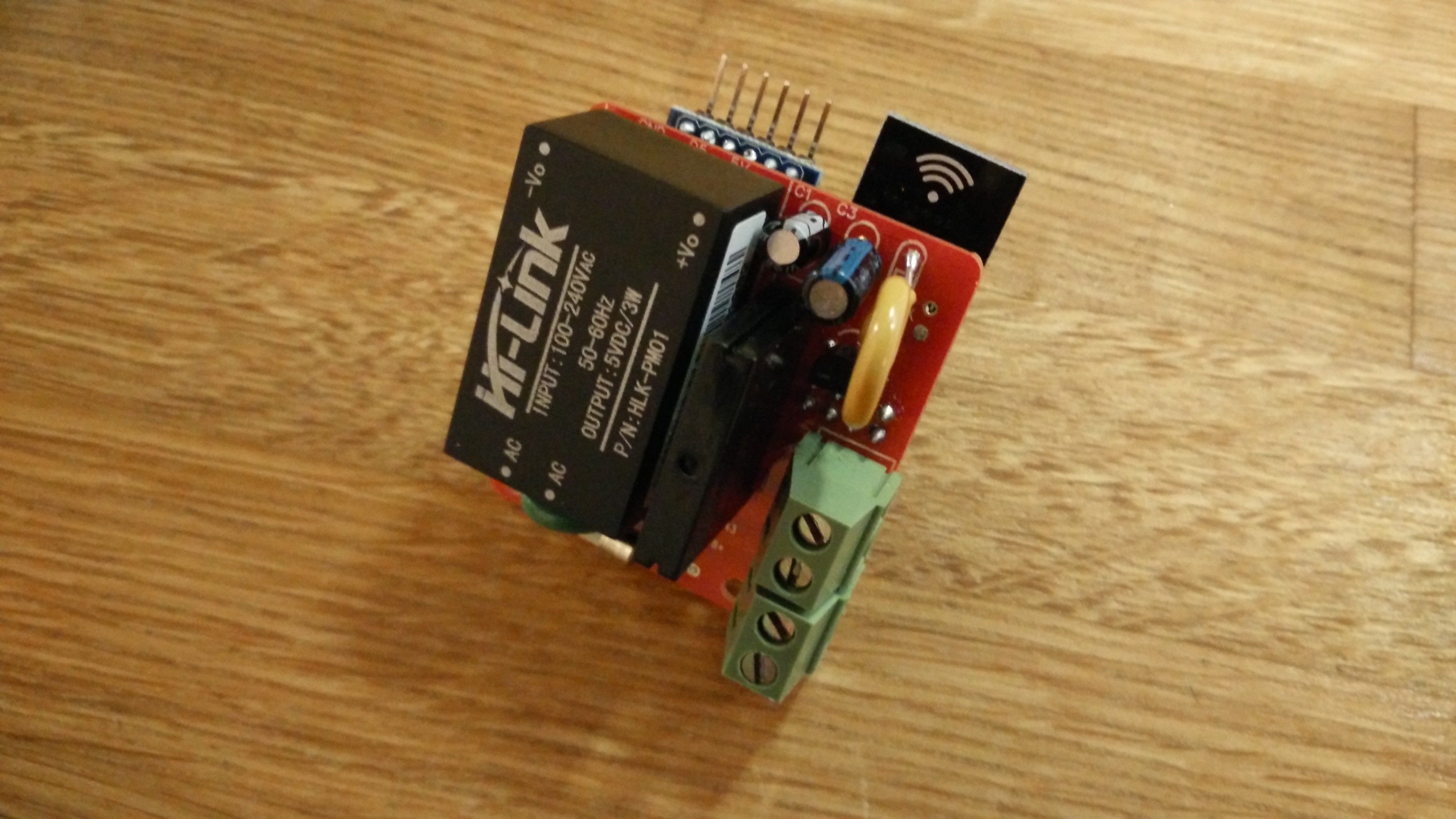
110v-230v AC to Mysensors PCB board


  • Hero Member

    Hi all,

    After all input you guys gave me, combined with the findings of this topic, I decided to go back to the drawing board.

    Before submitting my newly designed PCB I would like to make sure it doesn't contain any (obvious) mistakes.
    Two questions I still have are:

    • I assume it is correct that all ground pins are connected to each other? So both for the 5v parts of the circuit and the 3.3v circuit?
    • The HLK-PM01 seems to provide a quite stable voltage somewhere between 4.9 and 5.1 volts. If I understand correctly I should directly connect this to VCC input of the Arduino Pro Mini, and NOT to the RAW input voltage?

    Any other remarks on the current design are welcome as well of course! 🙂

    Schematic
    Schematic.png

    Components (from left to right)
    J1 2 Pin screw terminal (Power input)
    Fuse1 PTC Resettable Fuses 250V 1A TRF250-1000 PPTC Polymeric PTC PolySwitch
    Varistor1 Varistor 10D391K 10D-391K VDR 10K391 Metal voltage dependent resistor
    HLK-PM01 HLK-PM01 230v AC – 5v DC converter
    Fuse2 PTC Resettable Fuses 250V 1A TRF250-1000 PPTC Polymeric PTC PolySwitch
    Varistor2 SMD 1206 5.5V Varistor original Varistor resistor 100pcs/lot
    C1 100nF capacitor
    C2 100uF capacitor
    U3 LE33ACZ 5v to 3.3v converter
    C3 4.7uF capacitor
    NRF24L01 Normal NRF24L01(+) module
    Arduino Arduino Pro Mini 5v
    K1 G3MB-202P 240V AC 2A Solid State relay
    J2 2 Pin screw terminal


  • @aproxx here you use only Relay not a relay with button.
    my suggestion is that make design to use relay with button

    1439321581937-schematic.png

    Here I sketch 2-Relay and 2- switch


  • @aproxx please make this type of board, so that we can control two thing through one module


  • Hardware Contributor

    @aproxx I know my board is different of yours as I am using smd. But if you want to have a look, I have updated my first post here http://forum.mysensors.org/topic/1586/roller-shutter I am waiting for my pcb now..
    Maybe it can help you...

    For your schematics, what I would do is like @jemish said : buttons connector, maybe a resistor between arduino and relay. You are protecting input of HLK (with varistor..) it is ok. But you don't protect at output of relay.


  • Hero Member

    @jemish Yeah it seems like I totally forgot to add the switch in the schematic, but I do have it in place in my PCB design 🙂
    About adding a second relay.. I'm not sure about that yet. Maybe if I can still keep footprint of the board to a size less than 5 by 5 cm I'll add a second one. But it is certainly is a good idea though!

    @scalz I'll definitely have a closer look at your PCB design! Seems really interesting, but unfortunately I don't have the proper tools to go for SMD. Soldering a single SMD component is doable, but I'm not going to start soldering SMD Atmel chips 🙂
    About the resistor you mentioned: I assume the Solid State Relay which I mentioned doesn't need an external resistor between my arduino and the relay.. According to the datasheet the G3MB-202P-DC5 seems to have a build-in input resistor if I'm not mistaken.


  • Hardware Contributor

    @approx: I agree with you. first time I soldered small chips I was afraid as I am not electronician. On youtube there is lots of tutorials for smd soldering. I think maybe one day you should try with solder paste. It is magical! I don't always use it for atmel chips but it is easier.
    and of course flux, desoldering wick, and a magnifier is a must have too. and a 0.2mm tip for soldering iron..
    But your design is cool, I like it too! It could interest people.😃


  • @scalz (sorry OT) I am actually looking at getting a decent (aka not too expensive!) air gun and some paste - preferably with a syringe. Any recommendations on that?


  • Hardware Contributor

    @shabba: I have not an air solder yet, I would like to test it! I have not compared yet existing products. But I think it is useful for desoldering, soldering some chips. Not the best for res, capa...I would prefer solder iron.
    Like many people, I usually use flux and good soldering tin (0.3 with flux in it) with a 0.2 tip. And sometimes I use my solderpaste for fun and for some chips! Something i think I will try to make soon is a smd picker. and then a solder paste dispenser. another thing cool I would like to try is this http://operationalsmoke.blogspot.fr/2014/05/diy-usb-soldering-microscope.html but with a c920. Unfortunately not enough times...

    Sorry for OT too. See you soon


  • @aproxx when you completed the design of PCM board than please share with me as soon as possible.


  • Hero Member

    @jemish Of course I'll share the design and all related documents.. 🙂 I hope to have it finished in a few days, and will sure give an update when completed!


  • Hero Member

    As promised: In the attachment of this post you can find all required information to build this board.
    The zip file includes all required Gerber files, bill of materials, as well as the Schematic and PCB design (drawn using DipTrace).

    One remark: I've slightly adjusted the design to optimize the reception for the NRF24L01. The antenna of this chip is now placed slightly next to the custom PCB. Hopefully this will result in a better RF reception.
    Size is approximately 47 by 42mm.

    Download (Please be aware that this board is still untested at this moment, so please doublecheck things yourself before ordering!):
    Check latest post for updated version.


  • Hardware Contributor

    @approxx: nice board!
    could I give you one or two tips? as I have recently designed an ac board too...

    there is one or two trace which are 90° corner. maybe I am a little old school on this but it is preferable to have 45°. but it should work I think no problem.
    Your board will not draw too much AC current I think, and I don't know what are your trace widths for AC. but you can check here http://circuitcalculator.com/wordpress/2006/01/31/pcb-trace-width-calculator/ if you want to know width of trace regarding current flow. Then if you can't have the right width because of space... you can use soldermask layer stop and then you will be able to add soldering on all the AC trace and give it more strength for more current drawing. Because most of china fabhouse use 1oz copper. Some 2oz but more expensive.

    Just my 2cent tip, maybe you already know it, and have already ordered you board.


  • Hero Member

    @scalz Yeah usually I'm going for 45 degree angles as well, but I guess I just forgot for those few. However I do have full confidence in Dirty PCBs, so I'm sure there wouldn't be any disruptions in the trace.

    Regarding trace thickness/width: I've been doing some calculations as well, but with 1oz copper traces I would need extremely wide traces to come up with a decent copper volume. So my plan is to solder a thin wire at the bottom side of the PCB between the AC connection points. That's why I've got the AC and 5v DC circuits separated as much as possible. 🙂

    But thanks for the feedback anyway! And congrats on taking the first step of ordering the board! I'll be doing the same tomorrow.


  • Looking at your pcbs and looking the same time on my badly soldered dimmer.. i have the gut feeling i should maybe redo this with a proper pcb. 😅

    2015-08-17 23.07.49.jpg


  • @Oitzu said:

    my badly soldered dimmer.

    No way that is just like mine! 🙂 It's Perfect!

    Just Kidding I need to get my dimmers working properly also. You got the zerocross working right? 220v 110v? share sketch? will yours work locally with gateway off?


  • @DrJeff said:

    Just Kidding I need to get my dimmers working properly also. You got the zerocross working right? 220v 110v? share sketch? will yours work locally with gateway off?

    Yes the zerocrossing is working right. Shouldn't working with gateway off only be a matter of programming? ^^
    Built vor 220V, but should also run at 110V (with different resistors), need to check the specifications of the combonents again to verify that.

    I got no working MySensors sketch or a drawn pcb layout yet, but i can describe how it works.
    Left connectors are (up to down): LOAD: Phase, Neutral; Source: Neutral, Phase
    Right connectors are (up to down): GND, PWM Output, Zero-Crossing Input, VCC

    The Zerocrossing detection is done by the bridge rectifier and the zerocrossing detection module 4N25.
    The Signal goes to a INT-Pin of an arduino.

    In a test sketch i use a timer and the interrupt to do the correct pwm output.
    The pwm output goes to the MOC3021 (Opto) that will fire the TRIAC seen left from it.

    Little test sketch:

    #include  <TimerOne.h>
    
    //Config
    int INTPin = 0;
    int outputPin = 11;
    int dimLevel = 64; // Dim level (0(on)-128(off))
    int freqStep = 75; //50Hz, should be 65 for 60Hz
    
    //Global
    volatile int i=0; // Counter. Only fire if i >= dimLevel
    volatile boolean zeroCross=0;
    
    void setup() {                                      
      pinMode(outputPin, OUTPUT);
      attachInterrupt(INTPin, zero_cross_detect, RISING);
      Timer1.initialize(freqStep);
      Timer1.attachInterrupt(dim_check, freqStep);                                           
    }
    
    void zero_cross_detect() {    
      zeroCross = true;
      i=0;
      digitalWrite(outputPin, LOW);
    }                                 
    
    void dim_check() {                   
      if(zeroCross == true) {              
        if(i>=dimLevel) {                     
          digitalWrite(outputPin, HIGH);
          i=0;
          zeroCross = false;
        } 
        else {
          i++;                    
        }                                
      }                                  
    }                                   
    
    void loop() {                        
    }


  • @aproxx If I want to buy this module then.........
    If you sell this module then I am ready to buy ...


  • Hero Member

    @jemish I've made some minor changes to the board (nothing functional has been changed, just some updated silk screen and modified the 90 degree angles to 45 degree angles.)

    Please be aware that at this moment the board still isn't confirmed to be working. If you want to be 100% sure everything works properly, I strongly advise to wait for another 5-7 weeks. That way I can assemble the board myself and confirm everything is working as expected.


  • yes I like to wait for your responce.
    please reply fast as possible.


  • @Oitzu
    I seem to get all this working outside of MYSensors but I have very limited cut and paste ability in code. 🙂 So what I was wondering do you have the sketch for controlling the dimmer and just firing the triac integrated with MYSensors yet?


  • @aproxx so now, what is the progress??
    we will wait for your response.


  • Hero Member

    @jemish
    All components are at my desk at the moment. The only thing missing is.. The PCB itself. 🙂
    DirtyPCBs' website states that the board was shipped to me at August 24. My packets from China usually arrive about 2 or 3 weeks after they have been sent from China, so I expect it to arrive somewhere next week.
    After the boards have arrived I'll make sure to have it assembled in less than a week. 🙂


  • @aproxx please upload new design new that you make now.


  • Hero Member

    @jemish : The design which I've posted 2 weeks ago (A few posts above this one) is the latest design I have.


  • but, you said that you want to change something like 45 degree or 90 degree, so that ....


  • Hero Member

    @jemish : Yes, but that's already included in the design which I posted above.


  • @aproxx can you make design for 2- relay board....


  • @aproxx so, now what is the progress....we are waiting your response.....


  • Hero Member

    I received the newly designed PCB last weekend, and have been soldering/testing the board since it arrived. Just a few minor changes to the layout (not the schematic) and the board should be completely finished! So far the results look promising.
    @jemish: I'm currently re-working the design a bit and working on documentation, but I'll make sure to post the new and completely finished design by the end of the week!


  • Hero Member

    As promised, I've got an update for this project. The board has been tested in the past week, and everything is working as expected. Compared to the previous board I've posted, I have updated the following:
    • Solder pads of LE33CZ have been placed a little wider apart to avoid short circuit while soldering.
    • Solder pads of the resettable fuse (Fuse2) has been placed closer together to better fit the fuses of the BOM.
    • Moved the NRF24L01 connector a bit away from the solid state relay. Should make it easier to solder.
    • Moved Fuse2 to another location on the board, away from the 230v circuit.

    Some 3D pictures (Top and bottom):
    Top.png
    Bottom.png

    Anyone who is interested can order the PCB HERE

    Some documentation, and all gerber / DipTrace files (in case you would like to make some modifications) can be found here: MySensors board v3.2.3.zip.


  • I just ordered 20. Can't think what I will need them all for but better to be looking at them than looking for them 🙂

    Great work! Thanks!


  • Mod

    @aproxx I guess you use a different Arduino Pro Mini as the one in the 3D view, because its row of pins pointing towards us seems to get awfully close to the mains coming from "Power in", right?


  • @Yveaux
    I believe those are for the serial connection that usually are pointing up, or back for programing? It looks like they are just rendered as down in the 3D image? But I am curious how the clearance for the components on the other side (HLK) is when they are soldered, does it need some space off the board?


  • Hero Member

    @aproxx Could you share some photo's of the mounted board to get some feel or the 'real' thing? thanks


  • Hero Member

    @Yveaux: I'm using the standard Arduino Nano, but I agree that the 3D view looks a bit worrying. In real life it isn't needed to solder this row of pins to the Arduino, so it should be safe. So the assumption of @DrJeff is correct!
    The only reason why these pins look connected to the board is because I couldn't find a 3D design of the Arduino nano without these 6 pins soldered. 🙂
    But thanks for pointing this out, I'll add it to the documentation to make sure people aren't getting confused.

    @AWI: I'll try and see if I can take some decent pictures when I get home (in approximately 12 hours) and post them up here!


  • Hero Member

    For those who wanted to see some pictures of the board:
    IMG_20150921_194059 (Small).jpg IMG_20150921_194039 (Small).jpg IMG_20150921_194035 (Small).jpg IMG_20150921_194023 (Small).jpg IMG_20150921_192748 (Small).jpg IMG_20150921_192737 (Small).jpg IMG_20150921_192728 (Small).jpg

    Small notice: These pictures are of a slightly older design. The newer design has a few minor changes like better component placement and a permanent fuse instead of this resettable fuse. But these pictures should at least give you an idea on how everything looks like, and shows how really small it actually is.
    Also, I reinforced the traces of the 230v lines, which I absolutely recommend to do! (Although I do recommend to do it slightly more professional than I did on this prototype :))


  • Very nice. 👍 I ordered 10 boards on Saturday, can't wait for them to arrive.


  • Hero Member

    @aproxx Looks cleaner than the 3D view 👏


  • Hero Member

    @AWI Thanks for the kind words! I did my best on the soldering part, but the reinforcement of the 230v circuit could have done a bit better in my opinion. 🙂 Next time I would use an isolated wire to reinforce the 230v traces, but for a prototype build this was sufficient.


  • nice job....very nice....


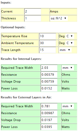
  • Nice job. Why do you need to bridge the 230V lines? Can't you just make the traces bigger? Is it really needed? The relay can only switch 2A. So the traces have to survive 2A, too. You can easily calculate the required traces with tools like this: http://circuitcalculator.com/wordpress/2006/01/31/pcb-trace-width-calculator/


  • Hero Member

    @Jan-Gatzke I've used a similar calculator before and according to these calculation it isn't mandatory.

    • Dirtypcbs.com claims to use 1oz/ft2 copper thickness (which seems to be 0.035mm).
    • The traces between the solid state relay and connectors are all 2mm wide.
    • Distance between the solid state relay and the connector on the edge is less than 20mm.

    That would lead to the following calculations:
    Schermafdruk 2015-09-22 13.35.55.png

    So you are right that it isn't mandatory to reinforce these traces. However, to be on the safe side I'm still planning to reinforce them. I know, it probably isn't necessary but it doesn't hurt putting this extra effort in, just to be completely safe. 🙂


  • Keep in mind, that you do not want to run the relay at 2A for a longer period of time. 2A at 230V means 460 W power consumption. Most devices / lights will consume less. So hopefully this will never be a problem.

    Again, great job. I will definitely order some of the pcbs, too.

    What about the other parts? Do you have some kind of link collection for Ebay/Ali? This would make it even easier to build the device.


  • Hero Member

    @Jan-Gatzke Indeed, most of my lights only consume like 10% of the maximum rated power, so I should be on the safe side for sure.

    I have attached a ZIP file which contains all required information in one of my previous posts (HERE). That one contains a Word document with all components and an AliExpress/Ebay link.

    I'll try and see if I can update the first post of this topic as well to include all important information.


  • Ok, lazy me didn't have a look at the zip. Tanks for the hint. 🙂


  • Admin

    @aproxx This looks very cool! I am curious what (if any) heat sink will be used with the solid state relay? I have never used a solid state relay but I have been reading about them and it seems that most are used with a heat sink. Maybe it depends on the amperage that will be switched though. Thanks!


  • Hero Member

    The SSR has an integrated heat sink according to the specs. Don't know if this is a knockoff and follows the same standard of quality though. Given the low A rating, and the fact that most of us will be switching a 10-20W worth of lights, I think it will be fine.

    I noticed the ceramic "Slow Blow Fuse (250v 0.3A)" was out of stock on Ebay. As was the 0.2A version. Someone is stocking up 🙂 Would it have to be a ceramic fuse?


  • Admin

    @bjornhallberg Thanks. I still have some reading to do... 🙂


  • @bjornhallberg said:

    was out of stock on Ebay. As was the 0.2A version. Someone is stocking up

    😔 oops! You wanted some?

    just kidding, let me check I have a line on parts I will see if they have some.


  • Hero Member

    @DrJeff I actually bought the 0.2A version myself before it was gone 🙂 But I was surprised to find how hard it was to find axial ceramic fuses of the right size or at the right price. Maybe we could find some sort of small fuse holder instead?


  • @bjornhallberg said:

    Maybe we could find some sort of small fuse holder instead?

    I know its probably not the best thing to do but I have just soldered on leads, bare wire. I just tin the metal first and scuff it a little. I have done the same thing to batteries with no ill effect.The key is get in and off quickly!


  • @aproxx I'm hoping to receive the boards soon (they were sent almost two weeks ago) and have one question for you.

    I've had a quick look at your example code in the Word document but I'm not familiar with Arduino Debouncing. My question is what kind of switch is the best to use, a standard On/Off switch or a Pulse switch?


  • Hero Member

    @mvdarend I'm not sure if I completely understand what you mean by "pulse switch"..
    I was planning on using a normal light switch, in order to have an on/off (open and closed) circuit.
    But it shouldn't be a problem to modify the code a bit in case you're using some other buttons (like a push button for example). I'm sure me or somebody else on this forum can help you with your code in case it shouldn't work out as expected. 🙂


  • @aproxx said:

    @mvdarend I'm not sure if I completely understand what you mean by "pulse switch"..

    Thanks for your reply, a 'pulse switch' is basically a push button type switch like you mentioned. I'll see if I can get it working when the boards come in. (I've already got all the other parts)


  • NIce little boards! I received mine yesterday 🙂 after a few hiccups I got it working fairly quickyl.

    Two small things that might need your attention:

    • The holes for fuse2 were too small for the resettable fuses I bought, had to drill them out a tiny bit.
    • I think the LE33 is the wrong way around in the pictures. I kept getting a "Check wires" message in the debugger. After checking a number of things I noticed that the voltage to the radio was too high. After looking at the diagrams I noticed that the LE33 is the wrong way around, after desoldering and turning it around (flat side facing Fuse2) the unit worked as expected.

    For anyone else that bought the 5.5v DC varistors from the given link, double check them before using them. I received a few that were defective, there was absolutely no resistance between the two poles. Causing Fuse2 to get a bit warm 🙂

    IMG_20151009_223249.jpg


  • Hardware Contributor

    Hi! Nice! 👍

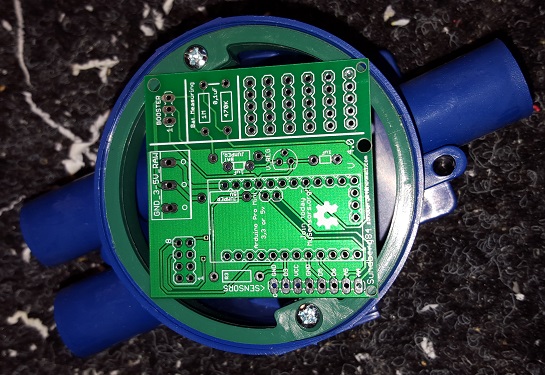
    Is this board 5x5cm? If so it might be to big for my in-wall projects.
    This is a board thats 5x5 on top of a standard whatsitsname...
    55.jpg


  • Hero Member

    @mvdarend Thanks for the feedback! Happy to hear that it's working fine on your side as well. Although I do find it strange that the LE33 seems to be the other way around on your board? Maybe I just made a mistake with the silkscreen, and should the LE33 be on the bottom side? Anyway, I'll make sure to address this as soon as I possible (probably somewhere during next week). Sorry for the possible inconvenience, but thanks for pointing this out! 🙂

    @sundberg84 The board dimension are about 4.2x4.7cm, so it is quite small. However, I'm afraid that because of the NRF24L01 module, and the 230v connections to it, it wouldn't really fit the box you have on that picture (assuming the board you have there is 5x5cm)..

    Somewhere in the next week or 2 I'll try to design a custom 3d printable plastic box for the board that I've designed. Together with a 2-relay board as requested by @jemish .


  • I spoke too soon... the unit seems to work well, but I hadn't tested if the relay actually switched or not. The status seems to change fine in the serial monitor, but it doesn't seem to be actually switching. I'll have to do some more troubleshooting.


  • Hero Member

    @aproxx My first project with your design, Thanks 👍
    p.s. the regulator needs to be mounted "reversed" from the silk screen. Some puzzling but a lot of fun and top result 💓
    upload-04a945b8-8cc0-4671-becd-0a72580c8b6b


  • Is it possible to add the option to be able to use RFM69 radio also?


  • The board looks really nice! Just one question though; what about temperature protection? In this thread people talks about gluing a thermal fuse on top of the HLK-PM01, is that something you considered or do you think it's unnecessary?


  • @cygnus said:

    The board looks really nice! Just one question though; what about temperature protection? In this thread people talks about gluing a thermal fuse on top of the HLK-PM01, is that something you considered or do you think it's unnecessary?

    Good point, been following this topic because of the other topic about the HLK-PM01 ad to dc regulator. And after extensive testing the outcome was that there should be added the thermal fuse because of additional safety. What do you all think?


  • @krizzziz
    I have seen in some commercial wall switches thermal cutoff/fuses they are usually to the top of the offending (heat producing components) not necessarily directly touching. I have definitely added them to mine for peace of mind. Like this one:
    upload-2d08b952-3efd-4445-a12c-e3c1393fcbcf
    http://i.imgur.com/rqOawGmm.jpg

    Just make sure you heat sink when soldering them into place and check them after installation.


  • Hero Member

    @mvdarend said:

    For anyone else that bought the 5.5v DC varistors from the given link, double check them before using them.

    I wish I would have read this a week ago. Would have spared me from a "WTF!" moment.


  • I'm trying to build this nice litte board. Got a long way but now i'm stuck.

    The BOM for version 3.2.3
    100nF + 100pF Capacitors
    4.7uF Capacitors

    Schematics.
    c1 100nF
    c2 100uF
    c3 4.7uf

    I'm don't have a lot of knowlegde but the 100uF seems te be missing from the BOM. The placement of this part is under the HLK. I have a lot of trouble place the C1 and C2.

    I have a ceramic one with number 104 in C2. I thought this is the 100nF. So should it be in C1? But it's so small and nice. And then C2 is missing from the BOM and the only 100uF I have from an other project is big. It realy won't fit under the HLK.

    Can some-one give some insight on the BOM, C1 and C2, Ceramic code numbers.
    This would realy help me and maybe a few others.

    Also on my board the holes for the fuse 2 where to small had to drill them out. Second the request for a thermal-fuse. But thanks for this great design.


  • What order did people solder the components on?


  • Anyone? The part list (ie mapping of CX etc) is in this post - not in the doc with the zip file so makes things very confusing.
    Thanks.


  • @aproxx Could you clarify the capacitors please? C2 on a post in this thread is 100uF but there are hard to get as ceramics and even the half height ones I have make the arduino stand very high off the board.

    Thanks muchly!


  • Hero Member


  • thanks for reply @AWI - The 100nf one does not go under - it is the 100uF one that does. I have a small electrolytic one (it is slightly smaller than the second link you mention) and there is still not enough space - my arduino is too low - I could try and find higher pin stands. I'm sure some ppl will go off and buy all these parts like me so I hope they are aware. Would have been ideal for a SMD really (like the varistor right beside it).


  • Hero Member

    @shabba I don't have a 100uF capacitor under the Arduino and don't think there needs to be one... Take a look at the pictures. The two large 4.7 and 100 uF are next to the black box


  • I still have trouble figuring out the C1 and C2. Here are some picture of my build so far.
    Not sure all the components are placed correctly.

    C1 is placed with a small 100nf (104) but BOM in zip say's this is wrong.
    As you can see i placed this one, cause the 100uf will not fit

    DSC_0232.JPG
    DSC_0234.JPG
    DSC_0236.JPG
    DSC_0237.JPG
    DSC_0239.JPG
    DSC_0242.JPG
    DSC_0245.JPG


  • Hero Member

    @Quinie looks correct. This is the position of the large capacitors (mind the polarity - minus to the edge of the board)

    upload-a8c45995-dbf9-4e64-8814-b1191a43be35

    I also noticed you mounted the regulator correct. 😉


  • So the regulator needs swapping about and the BOM cap values are incorrect from post (http://forum.mysensors.org/topic/1540/110v-230v-ac-to-mysensors-pcb-board/37) above that states :::
    C1 100nF capacitor
    C2 100uF capacitor
    C3 4.7uF capacitor

    ?


  • Hero Member

    Hmmm. I got the 5.5V DC varistor from another AliExpress seller and I'm a bit puzzled as to why it starts smoking after a few seconds. Tried several of them. The HLK gives a solid 5V output. I'm assuming I got some lower voltage varistors by mistake?


  • Hero Member

    @shabba Right... if you look at the schematics upload-a10f80dc-0eda-4c4b-aa49-e0bbc6f827a8 you can see that the two capacitors can be swapped without consequences


  • Hardware Contributor

    @bjornhallberg Maybe I've missed reading something, but why use a varistor for 5 Vdc and not a zener diode?


  • @AWI Thanks! Very true!


  • Hero Member

    @m26872 You're probably right, I just followed the BOM. I'll see if I can stock up on some diodes from AliExpress for future use.


  • Hero Member

    Whould a 5.1V zener work?

    edit: removed the link to the product so that no one would buy it the specs of it is to tight to be used with HLK.


  • Just a stupid question, the "G3MB-202P DC-AC PCB SSR In 5VDC,Out 240V AC 2A " What happens if I forget and plug something more power-hungry like a toaster or a microwave-owen? does any of the fuses blow or does the relay break ?


  • Hero Member

    there is no fuse on the relay switch so I guess either the PCB or the relay will fail.


  • Hardware Contributor

    I've seen commercial products with a thermal fuse glued to the switching side of the relay. Maybe that would help some in such situation.


  • Hardware Contributor

    @korttoma A 5.1V zener is probably too tight. The HLK seems rated 5+/-0.2V.


  • Hero Member

    @m26872 Indeed, mine is 5.08V (with no load). I ordered some 5.1V and 5.6V 1206 SMD diodes from Ali for future use. Plus some 3.6V. And a set of DIP diodes.


  • Hero Member

    @bjornhallberg said:

    I ordered some 5.1V and 5.6V 1206 SMD diodes

    Just to remember, the typical zeners are 1W , which gives a max of 200mA of output capacity, pretty enough for Arduino+radio, but maybe not enough for many relays / Leds etc. And if they burn due overload, they will allow all voltage/current flowing from PSU into arduino.

    That explains why we suggested the varistor, in order to short the PSU output and trigger its internal protection. Strange that your varistors didn't survive... Bad lot? Maybe they are not 5.5V as stated?


  • Hardware Contributor

    @rvendrame
    No.
    The zener will only lead current during over voltage condition and only needs to dissapate enough energy till one of your (multiple?) over current protection trips. Just as your varistor setup is supposed to work.


  • Hero Member

    @m26872 , is it also true in case the PSU itself fail? And what happens if the circuit consumes more current than zener rating? I'm my (poor) knowledge, zeners are more relevant for stabilization, while varistor are effective 'protection' devices...


  • @mvdarend You discover your issue with the relay?


  • Hardware Contributor

    @rvendrame
    since we're discussing the PSU secondary side (output side), I think we already presume errors with the PSU. A fuse (over current protection) on the secondary is not just there as a back-up if the PSU internal over current protection fails. The fuse will also prevent your over voltage protection (zener, varistor, ...) from overload/burn/start a fire.

    The current from PSU to load will not pass through the zener and hence the rating is irrelevant from that perspective. In other applications where a zener is used as voltage regulator, the full load current will pass through the zener when in idleing and then the rating is critical.


  • Hero Member

    @m26872 so how do we need to rate the zener? Should the zener be rated so that the fuse will blow before the zener brakes from the current it passes due to an over voltage situation? Or is it OK that the zener brakes to as long as it takes out the fuse first. Then an automatic fuse will no longer work.


  • @shabba said:

    @mvdarend You discover your issue with the relay?

    Sorry, since that post I tried a few small things. But then I got caught up in other projects/work/family 🙂 and haven't had time time to look into it further.


  • Hardware Contributor

    @korttoma Good questions. As always a trade-off of risk, cost, space, taste, etc. They should already be answered in the varistor case though. Personally I think it's overkill with additional overvoltage protection at the low volt secondary side of a good quality PSU and an inexpensive load - fuse, capacitors and regulators should be more than enough. Focus should be the primary side protections.

    Edit: Btw. Found some reading. See p.44


  • Hero Member

    Just a quick post to confirm I got the relays working as well (with Domoticz). I didn't read the schematic at first and just assumed how the mains and relay external wiring should be done. Still no idea about the smoking varistor.


  • I thought all my relays were shot as I was not getting continuity on the load pins when I applied 5V. I checked resistance and there is just over 2K when 5V applied and infinite when none. I am going to put back together assuming the 240V A/C will pass through just fine.


  • What would cause no power to VCC when connected to mains (even though there is 5V at end of HLK-PM01) - if I bring that 5V with a jumper to VCC it works. Also works fine when connected to the serial port - Bad DC varistor?


  • Hero Member

    @shabba

    The only thing between the HLK-PM01 and VCC is Fuse2. Check the Schematic. But yes a shorted varistor will in the combination with the fuse bring VCC to 0V. I experienced this also since the 5.5V varistors I bought from the link in the documentation (Ali seller Unionup Electronic Mall) did not work.

    Seems like there is quite many of us that are having problems with the 5.5V varistors. I measured a few from my batch and they all show 0.4ohm with a multimeter, should they not have something like infinite resistance unless they get more then the 5.5V? My multimeter gives 0.6V when it measures resistance.


  • Hero Member

    @korttoma Say what...? You measure .4 ohms on your Varistor? I think you found your problem. 😠

    I have only ever used Varistor protection on the primary side, so I've got no experience with low voltage Varistors, but I don't think it should ever read .4.. Should be infinite.


  • Hello everyone,

    Since we probably wanting this for multiple destinations, what if we used a centralized way at our home powerswitch.

    We could stack multiple boards, and just use one arduino nano and one nRF on top of it. We just have to care about link each stack to a different arduino output.

    Based in this idea we could create a second pcb for stack mounting, this board will just have the SSR and a deep switch for easy selectable arduino output. To make this ok we should connect each home powerswitch to each stack, another way exist if we use the main supply of the bottom board for all stacks, and place our circuit before our home power switch, but this is not recommendable.

    For minimum stack size SSR should be horizontal mounted.

    The advantages are obvious, just one arduino and nRF, one ac-dc and regulator for all home switches. Super low volume occupied and no more size constraints inside wall switches.

    I don't have time to go forward and design this, so if someone wants it please go for it!! 😃

    PS - Since we just use one arduino output per stack, we could avoid deep switch cost and configure by soldering selected track.


  • Hardware Contributor

    @BSoft I had this idea also and have been working on a pcb for some weeks now.
    Its a 5x5 cm PCB you cut in halv so you get a 2 pcs which are 2.5x5cm - and they are stackable (like a shield).

    1.JPG

    This is how i plan to stack them: (Blue inwall socket behind).
    2.JPG

    On the bottom you have the high power and HK 240->5v converter.
    Then in the middle between the pcbs you have the radio and arduino and on top whatever you wants.
    I have made outputs for LCD screen, buttons and/or motion.

    There are still much work in progress here but so far this is my thoughts... and it fits inside the typical wall hole.
    This will not be ready for atleast some week, and the three weeks or so with order/deliver time.

    I will create my own post to get input on this when im done and If someone else knows and want to improve the design i can send over the files.


Log in to reply
 

Suggested Topics

  • 87
  • 6
  • 7
  • 1
  • 10
  • 7

0
Online

11.4k
Users

11.1k
Topics

112.7k
Posts