converting 12v to 5v
-
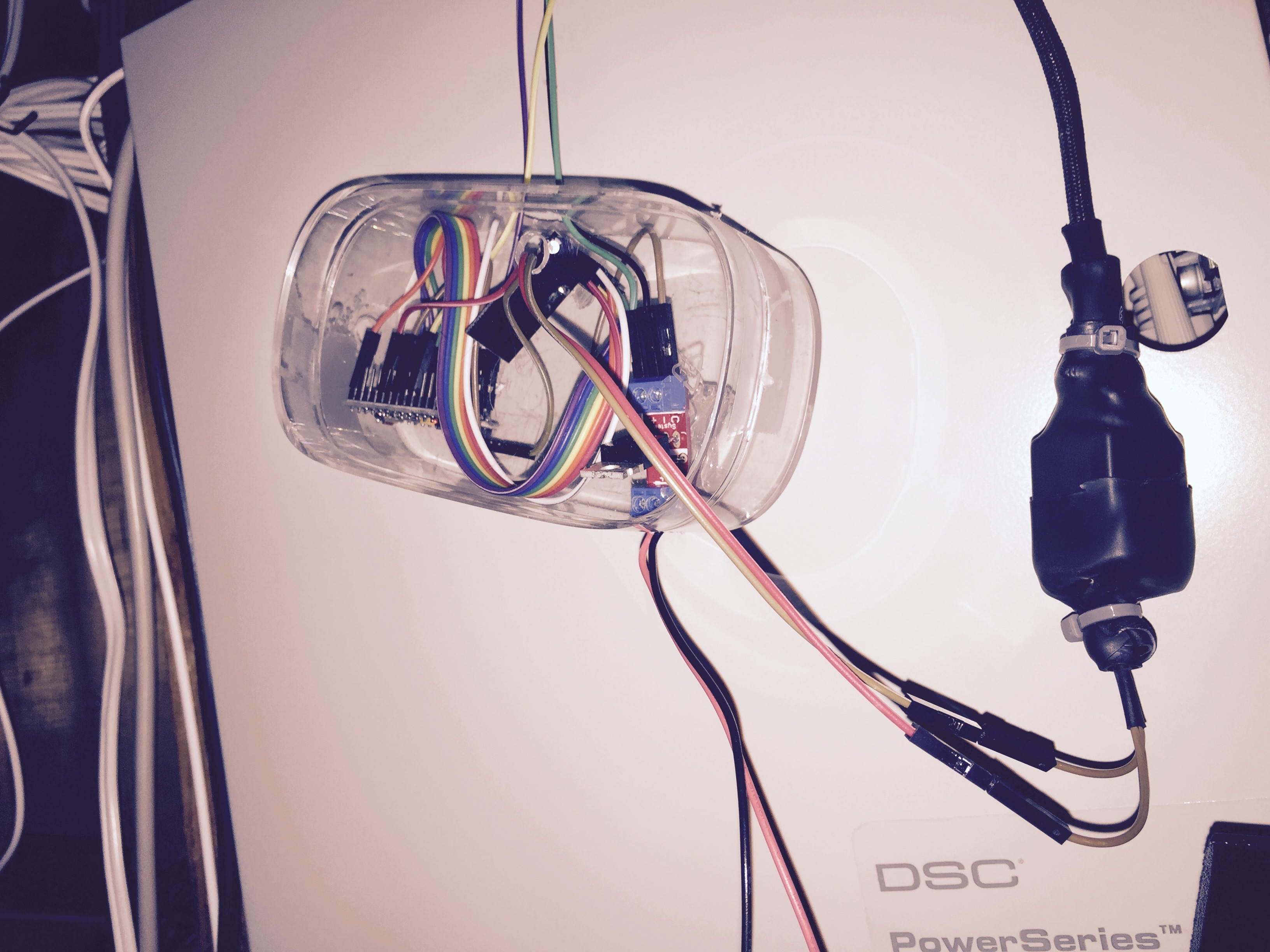
I added a doorbell alert with mySensors back in the fall -- I was going to post the code here, but I seem to have misplaced it. I have a trigger going to the VERA and a mosfet driving a couple of feet of bright LEDs strung over either side of the door frame between the two sides of the basement. These flashes a few times when the bell is rung, and the vera sends me a prowl message as well. I haven't missed any deliveries since adding it.
However, my 1955 era house here in the US uses AC voltage for the doorbell circuit ( it seems most, but not all, here in the US do as well ). Since the actual transformer is in a difficult to access area of the attic ( I think I code violation now ), I tapped into the wires as they run from the door bell button to the actual bell, this line was easily accessible in the unfinished side of the basement.
I just built a small bridge rectifier from 4 diodes 'dead bug' style on the pins of a relay, and covered the whole thing in some shrink. The relay just grounds a pin on a pro-mini. The pro-mini is just powered by a scavanged wall-wart which also provides enough current to flash the LEDs...
-
I added a doorbell alert with mySensors back in the fall -- I was going to post the code here, but I seem to have misplaced it. I have a trigger going to the VERA and a mosfet driving a couple of feet of bright LEDs strung over either side of the door frame between the two sides of the basement. These flashes a few times when the bell is rung, and the vera sends me a prowl message as well. I haven't missed any deliveries since adding it.
However, my 1955 era house here in the US uses AC voltage for the doorbell circuit ( it seems most, but not all, here in the US do as well ). Since the actual transformer is in a difficult to access area of the attic ( I think I code violation now ), I tapped into the wires as they run from the door bell button to the actual bell, this line was easily accessible in the unfinished side of the basement.
I just built a small bridge rectifier from 4 diodes 'dead bug' style on the pins of a relay, and covered the whole thing in some shrink. The relay just grounds a pin on a pro-mini. The pro-mini is just powered by a scavanged wall-wart which also provides enough current to flash the LEDs...
@soward yep.... Mine will send me hangouts message. And probably also a snapshot of who ever dared to ring my bell....
I have no idea what half of the terms you used means but will look that up when I am home. Dead bug? Bridge rectifier?I am actuslky luckier than I thought. The ring just short two wires so can trigger the nano directly. Its so easy its frightening....
-
dead bug is just a term for soldering together components w/o a breadboard or similar to put them on -- the resulting bits of electronics with wire 'legs' sticking out looks sorta like a dead bug. There's an art to doing it and making it still look nice which I never learned.
A bridge rectifier is a very simply way to convert AC into DC by using 2 (for a 1/2 wave) or 4 (for a full wave) diodes. Wikipedia probably has a better explanation than I could come up with though.
I added the lights as a secondary feature, since sometimes the lag of getting the message out and back to my phone was enough that I could miss someone -- that and I might have the phone on the charger, and not hear it (or be on the phone and not be able to see the message, etc).
regardless, sounds like your bell is a bit easier to work with than mine was.
I'd like to have a camera there as well, but it's going to be a challenge to get one mounted appropriately.
-
For what it's worth, I have a couple of the power supply boards from the OP that I'm using with a bridge rectifier to convert from a 24VAC sprinkler system to DC voltages appropriate for Arduino. Much cheaper to get the rectifier and DC-DC board separately than a dedicated AC-DC board that is effectively the same thing. If memory serves, I think my doorbell is also on a 24VAC transformer, so that would be appropriate here, too.
-
dead bug is just a term for soldering together components w/o a breadboard or similar to put them on -- the resulting bits of electronics with wire 'legs' sticking out looks sorta like a dead bug. There's an art to doing it and making it still look nice which I never learned.
A bridge rectifier is a very simply way to convert AC into DC by using 2 (for a 1/2 wave) or 4 (for a full wave) diodes. Wikipedia probably has a better explanation than I could come up with though.
I added the lights as a secondary feature, since sometimes the lag of getting the message out and back to my phone was enough that I could miss someone -- that and I might have the phone on the charger, and not hear it (or be on the phone and not be able to see the message, etc).
regardless, sounds like your bell is a bit easier to work with than mine was.
I'd like to have a camera there as well, but it's going to be a challenge to get one mounted appropriately.
@soward OK, I knew it was too easy to be true. apparently the transformer is 9v AC and the doorbell ring closes ~6v dc circuit that has the tiniest current on it (9ma). So, I can't steal current from the 6vdc so need to use the 9vac... so, bridge rectifier? and how do I "sense" the closing of the circuit without triggering a doorbell ring? I tried connecting the arduino with pin 3 and gnd in parallel to the door ring but it triggers a continuous ring. darn, and i thought that this at least will be simple!
-
This post is deleted!
-
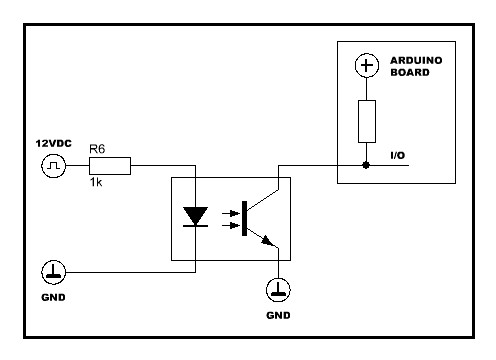
Maybe if you post the circuit, it will be easy to understand. Anyway, I think the less-invasive method is by using a optocoupler:
@rvendrame here is the page from the manual:
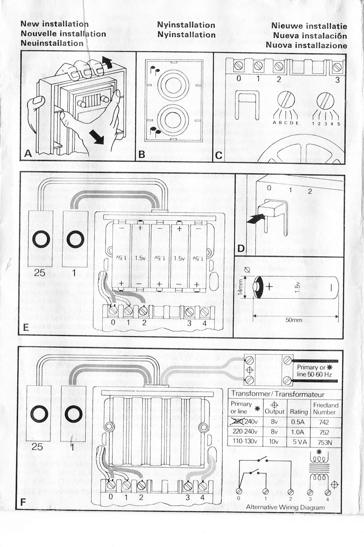
my installation is the one without the batteries,
i'll get some optocouplers and play. Thanks! -
@rvendrame here is the page from the manual:
my installation is the one without the batteries,
i'll get some optocouplers and play. Thanks!@Moshe-Livne Do you have a volt meter? Than measure between 0 and 1 while pressing the button and releasing it (or 0 and 2, depending which one is used) and than post your measurements. From the pictures I imagine that it is a DC circuit.
-
@Moshe-Livne Do you have a volt meter? Than measure between 0 and 1 while pressing the button and releasing it (or 0 and 2, depending which one is used) and than post your measurements. From the pictures I imagine that it is a DC circuit.
@rvendrame Oh wow. there are zillions of kinds... As aliexpress are a bit thin on details, anyone knows when one I should get to detect 6v 6ma ?
-
@Moshe-Livne Do you have a volt meter? Than measure between 0 and 1 while pressing the button and releasing it (or 0 and 2, depending which one is used) and than post your measurements. From the pictures I imagine that it is a DC circuit.
@AWI It is 6vdc, about 6ma current. i tried to tap it for powering the arduino but its not enough
-
@Moshe-Livne , it should be simpler than that --- Just connect the ground of the doorbell to arduino's ground, and use a voltage divider below to divide the +12v by lets say, 3, and connect it to any arduino input pin.
R1 = 670K and R2 = 470K should do the trick... 12V will become ~4V , and digitalRead() will read '1' when the bell rings (and zero when idle).
@Moshe-Livne going back to an earlier suggestion from @rvendrame (adapted a little for the situation)
Current is not important here as long as you do don't power the arduino from it. Just connect the ground of the doorbell to arduino's ground, and use a voltage divider below in parallel (U1) with the pushbutton. This divides the voltage of +6v by 1.5, and can be connected to any arduino input pin (Digital or Analog).
R1 = 470K and R2 = 670K should do the trick... 6V (U1) will become ~4V (U2) , and digitalRead() will read 'low' when the bell rings (and 'high' when idle).
-
@Moshe-Livne going back to an earlier suggestion from @rvendrame (adapted a little for the situation)
Current is not important here as long as you do don't power the arduino from it. Just connect the ground of the doorbell to arduino's ground, and use a voltage divider below in parallel (U1) with the pushbutton. This divides the voltage of +6v by 1.5, and can be connected to any arduino input pin (Digital or Analog).
R1 = 470K and R2 = 670K should do the trick... 6V (U1) will become ~4V (U2) , and digitalRead() will read 'low' when the bell rings (and 'high' when idle).
@AWI Errrr tried something similar before and the bell was ringing continuously as if the arduino acted as a short. might be something stupid i did. I excel in these. maybe defined the pin as output. will double check tomorrow.
Thanks! -
hmm.. only 6v DC?
why use optocouplers for that? Could also be done very simple with a resistor and one or two diodes.
connect gnd together, a 10-100k resistor in line with the +6V signal to the input on arduino, and a clamping diode to VCC (optionally a second clamping diode to GND for good measures).
See the first answer to the question here http://electronics.stackexchange.com/questions/45127/what-kind-of-diode-to-use-with-adc-inputs
-
hmm.. only 6v DC?
why use optocouplers for that? Could also be done very simple with a resistor and one or two diodes.
connect gnd together, a 10-100k resistor in line with the +6V signal to the input on arduino, and a clamping diode to VCC (optionally a second clamping diode to GND for good measures).
See the first answer to the question here http://electronics.stackexchange.com/questions/45127/what-kind-of-diode-to-use-with-adc-inputs
@tbowmo SO, just re-iterating so I wont do something stupid:
- I still need a bridge rectifier or some sort of ac-dc regulator/transformer to drive the arduino as the dc circuit does not have enough juice
- the circuit will look something like:
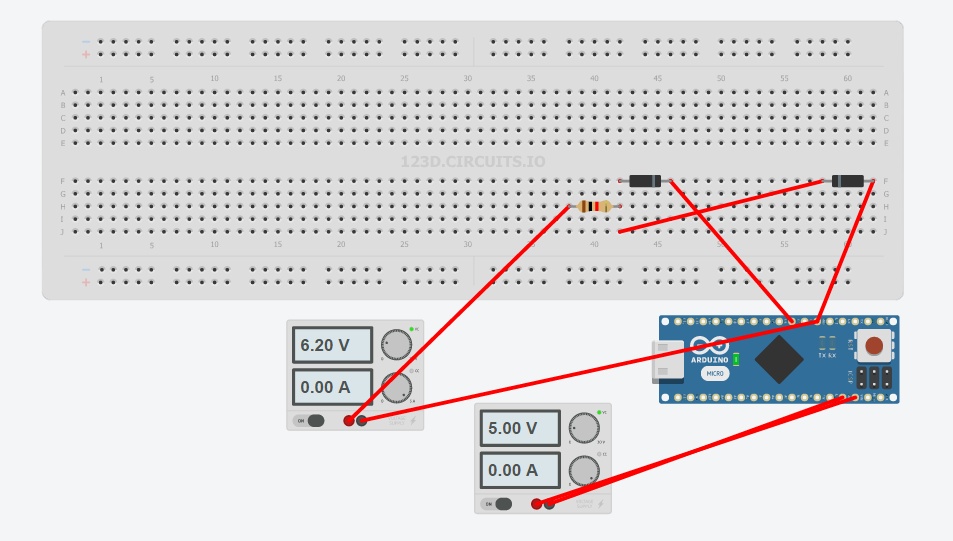
(the simulation shows zero current so i probably did something wrong)
Again, thank you for your patience.
-
hmm.. only 6v DC?
why use optocouplers for that? Could also be done very simple with a resistor and one or two diodes.
connect gnd together, a 10-100k resistor in line with the +6V signal to the input on arduino, and a clamping diode to VCC (optionally a second clamping diode to GND for good measures).
See the first answer to the question here http://electronics.stackexchange.com/questions/45127/what-kind-of-diode-to-use-with-adc-inputs
@tbowmo added the door bell to the simulation and its working. you are the bestest! now to get some diodes.....
-
That doesn't look quite right. If you look at the link I provided, you will see that the resistor is in line with the signal from "outside" to the arduino. So 1 side goes to the doorbell, the other go to the arduino pin. Then the two diodes go from arduino pin and vcc, and arduino and gnd.
-
That doesn't look quite right. If you look at the link I provided, you will see that the resistor is in line with the signal from "outside" to the arduino. So 1 side goes to the doorbell, the other go to the arduino pin. Then the two diodes go from arduino pin and vcc, and arduino and gnd.
@tbowmo did I get it right now?
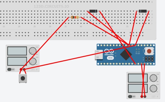
its a shame that they don't have ac power supply there so i can't simulate the rectifier. nifty site... -
Without knowing the details of the doorbell, I would think it is something like this.. That is, the doorbell get power, when the button is pressed, and makes a connection to GND. So this would be the circuit that I would create:
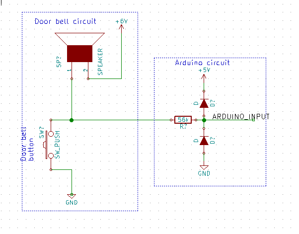
It's only the arduino part you should make, the rest is the existing doorbell.. The resistor should be high value, I've put in 56Kohm, but something in the order of 56-220K ohm, whatever you have in your parts bin :)