Skip to content
  • OpenHardware.io
  • Categories
  • Recent
  • Tags
  • Popular
Skins
  • Light
  • Brite
  • Cerulean
  • Cosmo
  • Flatly
  • Journal
  • Litera
  • Lumen
  • Lux
  • Materia
  • Minty
  • Morph
  • Pulse
  • Sandstone
  • Simplex
  • Sketchy
  • Spacelab
  • United
  • Yeti
  • Zephyr
  • Dark
  • Cyborg
  • Darkly
  • Quartz
  • Slate
  • Solar
  • Superhero
  • Vapor

  • Default (No Skin)
  • No Skin
Collapse
Brand Logo
  1. Home
  2. Hardware
  3. Roller Shutter
  • Getting Started
  • Controller
  • Build
  • Hardware
  • Download/API
  • Forum
  • Store

Roller Shutter

Scheduled Pinned Locked Moved Hardware
87 Posts 23 Posters 57.5k Views 32 Watching
  • Oldest to Newest
  • Newest to Oldest
  • Most Votes
Reply
  • Reply as topic
Log in to reply
This topic has been deleted. Only users with topic management privileges can see it.
  • scalzS Offline
    scalzS Offline
    scalz
    Hardware Contributor
    wrote on last edited by scalz
    #6

    So, here my files (need to be tested) : https://github.com/scalz/MySensors-HW/tree/development/RollerShutterNode_small
    Now I will work on my sketch and release when all will be ok.

    1 Reply Last reply
    0
    • F Offline
      F Offline
      Fabien
      wrote on last edited by
      #7

      I follow your work. Very interresting.

      1 Reply Last reply
      0
      • tbowmoT Offline
        tbowmoT Offline
        tbowmo
        Admin
        wrote on last edited by
        #8

        @scalz

        One question, why use an arduino board on top of it? You could just add the atmega chip directly to your board. You have SMD components on it anyways, so one more or less, is nothing..

        1 Reply Last reply
        0
        • scalzS Offline
          scalzS Offline
          scalz
          Hardware Contributor
          wrote on last edited by scalz
          #9

          @tbowmo : I agree with you. and I was thinking to do like this. But if I had choosen this way, I would have used 0805 (but not under, it makes me nervous, lol) and maybe using lnk306 or tny to have compact transfo. So it would be less fun for those who just want to take files and are not friend with soldering. So I have 1206 (easy to soldier), and you are right there are some small ics but just a few... But it's sure, those who take files knows soldering I think.

          Humm, you are tempting me to try to make it smaller version but I have others projects..You are right it could be smaller...I will see.

          Thank you , I'm very interested with your feedback. I am learning a lot here.

          1 Reply Last reply
          0
          • rvendrameR Offline
            rvendrameR Offline
            rvendrame
            Hero Member
            wrote on last edited by
            #10

            @scalz , it looks you will power the motors from AC Mains (through Fuse F1 + ACS712). Maybe you could add a side track for those who want to use 12V or 24V motors instead?

            Home Assistant / Vera Plus UI7
            ESP8266 GW + mySensors 2.3.2
            Alexa / Google Home

            1 Reply Last reply
            0
            • tbowmoT Offline
              tbowmoT Offline
              tbowmo
              Admin
              wrote on last edited by tbowmo
              #11

              @scalz

              I would suggest that you look at kicad instead, we have some mysensor specific parts in a common repo on github. Look at mysensors-kicad project on github

              1 Reply Last reply
              0
              • scalzS Offline
                scalzS Offline
                scalz
                Hardware Contributor
                wrote on last edited by scalz
                #12

                @rvendrame: exactly, I saw my mistake today. I will update files soon.

                @tbowmo: thank you for advice. next time I will think about it.
                For mysensors kicad project, wow, thank you for the link. team mysensors is making a great work. I noticed last weeks there is a kicad movement.
                Too bad I started to learn Eagle some months ago and I am just starting to like it. What I like too with eagle is lots of libs, and that I can get some footprints at farnell. But in other hand when I see all of your projects with 3d rendering, it is very hard to not have a look. And kicad is opensource...and if I can contribute..

                1 Reply Last reply
                0
                • scalzS Offline
                  scalzS Offline
                  scalz
                  Hardware Contributor
                  wrote on last edited by scalz
                  #13

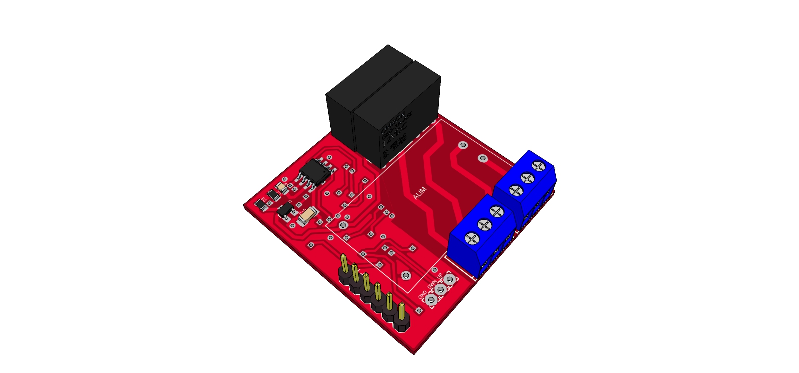
                  I updated screenshots and my github files. Now I think it can handle 12-220v motors. I had to change screw terminals (it was 5mm before, 3.5 now, i hope it is good). I have no place for capa snubber (too big unfortunately ) it will have to be external if needed. And I removed fuse too. Because it could change if 24v or 220v motor (not same current for 90w-24V and 90W-220v) and it is not easy to place it. So it will have to be external too if needed.

                  In case using 220v motors, now it needs to tie together Source and 12_220(Live) at the screw terminals.

                  I will see if I can make it better and smaller in the future (to put it in wall) and designed with kicad:wink:

                  1 Reply Last reply
                  0
                  • scalzS Offline
                    scalzS Offline
                    scalz
                    Hardware Contributor
                    wrote on last edited by scalz
                    #14

                    Hi,

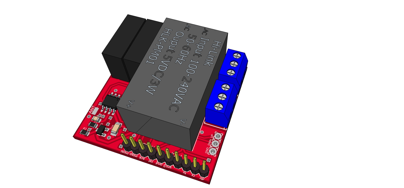
                    So, I tried to reduce size board to be able to fit in wall. I thought about using switching ic or to use sealed ac dc step down. not very easy choice but I keep the sealed (for galvanic protection), because I think it should not gain so much space finally and sw ic is more expensive to use. RFs footprints, atmel, eeprom... takes place too.

                    Here is how it looks for the moment. I just tried 3d for eagle to see so 3d rendering not complete.
                    It is 42x43mm
                    Top: power, relay, ldo reg, eeprom, ftdi connector.
                    Untitled.jpg
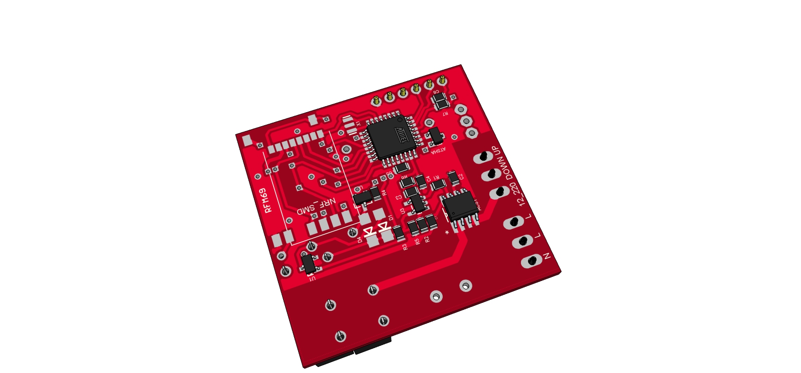
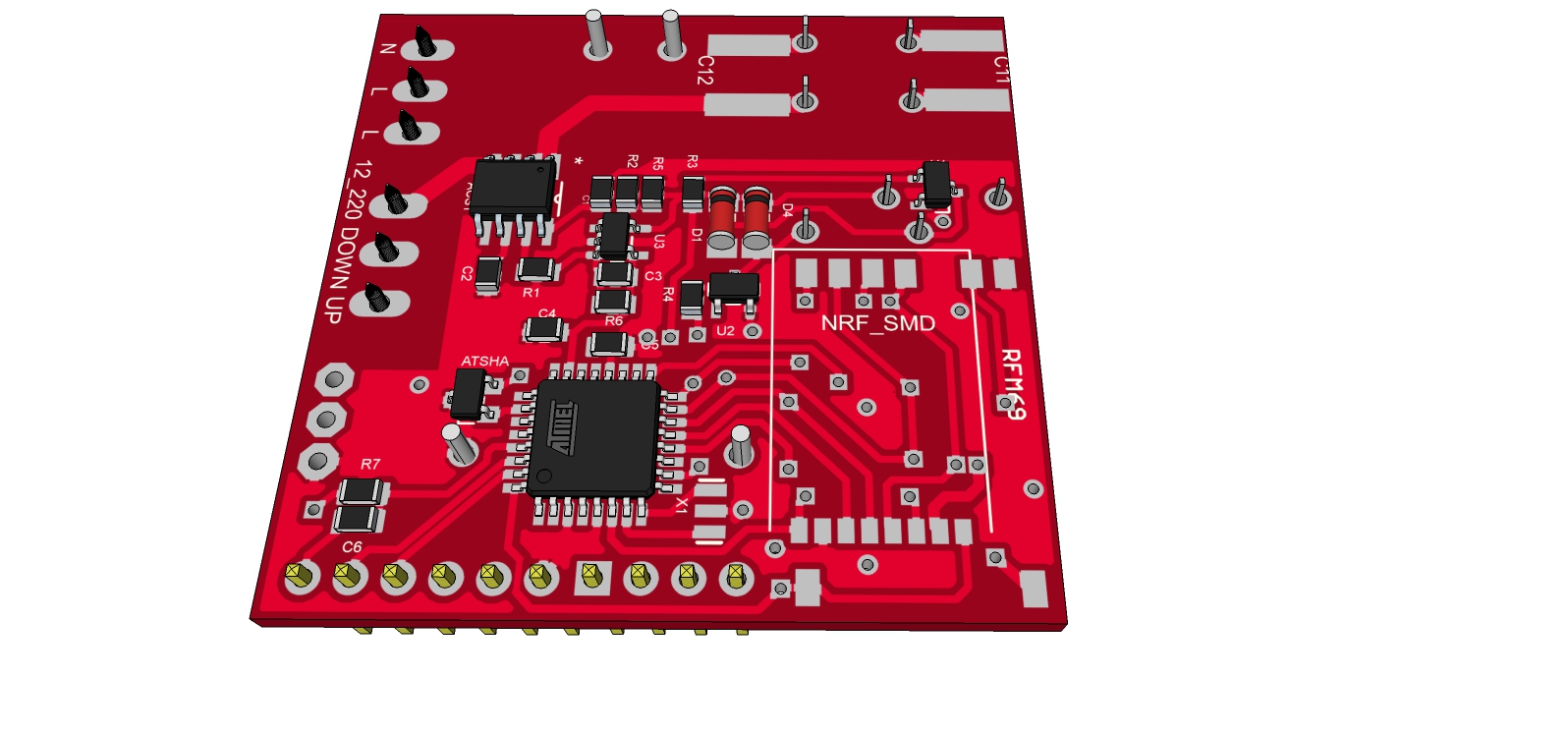
Bottom: atmel, atsha, acs712, nrf smd & rfm footprint
                    it is almost 0805 (i am just seeing I missed 2diodes).
                    Untitled2.jpg

                    But as you can see there is no snubber? I am thinking to add a capa only. Do you have a good not expensive ref smd that I can put on bottom.??
                    And there is no AVRSPI connector for the moment I need to find a little place for it, not easy.
                    Any remarks?

                    See you soon

                    1 Reply Last reply
                    0
                    • F Offline
                      F Offline
                      Fabien
                      wrote on last edited by
                      #15

                      Take car about antenna position (no metal just under the antenna). I experience some issues with sensebender micro and FTDI connector just under the antenna. And perhaps you can use small SSR relay.

                      1 Reply Last reply
                      0
                      • tbowmoT Offline
                        tbowmoT Offline
                        tbowmo
                        Admin
                        wrote on last edited by
                        #16

                        @scalz

                        As @Fabien just mentioned, you should keep the area under, and around, the antenna of the NRF clear of any tracks, and components.. Otherwise you are asking for trouble..

                        1 Reply Last reply
                        0
                        • scalzS Offline
                          scalzS Offline
                          scalz
                          Hardware Contributor
                          wrote on last edited by scalz
                          #17

                          @Fabien @tbowmo: thank you very much for your feedback.
                          So no tracks under the chip, or on the other plane? Arrgh, I will try. Is it related to nrf because on moteino designs it seems rfm don't care about it? Anyway I don't want to have problems. I don't know how I will do that but I will see this evening.Last night, I added spi for programmer so it's cool. I found capa for snubber but 2220 size...

                          And for small SSR, I thought about it but the board must handle 12/24v motors too so current won't be the same and small SSR won't like that. That is why I choosed these relays. I want to be able to handle 12/24 and 220v so the board would be useful for lots of application.
                          I was lazy to move to kicad but I will move for sure :flushed:

                          1 Reply Last reply
                          0
                          • F Offline
                            F Offline
                            Fabien
                            wrote on last edited by
                            #18

                            No track under the chip. I use kicad for few years now and it's ok !

                            1 Reply Last reply
                            0
                            • scalzS Offline
                              scalzS Offline
                              scalz
                              Hardware Contributor
                              wrote on last edited by
                              #19

                              @fabien: so not under chip, but other side of board is ok i think? Anyway, I think I will have to do some reroute. Not easy. I am not electronician. I'm database soft archi. So I have not done lots of pcb yet. I am learning.. but at my job I played a lot with mikroelectronika even if I am not in charge to design pcb.
                              And I think I made a wrong choice with eagle (I saw lots of libs so I thought it would be easier. But I have to make lots of parts myself so...).
                              Here what I did last night : moved ant smd for rfm, spi connector, and 3d model for stepdown. Not a lot of things. And, tried to place snubber, but not good, clearance drc errors..I am thinking to add snubber externally.
                              Untitled.jpg Untitled2.jpg Next screenshot I hope all will be ok :smiley:

                              @tbowmo: which tools do you use to create 3d models for Kicad? I tried Sketchup yesterday but don't like interface as I usually use Solidworks at job when needed. Would be great if I could export Solidworks to kicad, I will see if it's possible..

                              1 Reply Last reply
                              0
                              • tbowmoT Offline
                                tbowmoT Offline
                                tbowmo
                                Admin
                                wrote on last edited by
                                #20

                                @scalz

                                rfm modules have an external antenna, that is why they can be mounted like they do on moteino boards.

                                NRF modules incorporates an anteanna, and you need to keep the anteanna area (+ some space around it) clear of components and tracks. on both sides of the PCB. Otherwise they will interfere with the antenna radiation.

                                I use the build in 3D viewer in kicad. (Using almost bleeding edge of kicad on linux, with additions from CERN)

                                1 Reply Last reply
                                0
                                • scalzS Offline
                                  scalzS Offline
                                  scalz
                                  Hardware Contributor
                                  wrote on last edited by
                                  #21

                                  @tbowmo: thank you for your explanation. So I think it is not a good news for me (nrf24) aaaaaaa I will loose my hairs on this:sweat_smile: even if I plan to use rfm, my brother have a lots of nrf24. I think he will need move to rfm. But I will try, big challenge for me.
                                  For kicad, interesting info, thanks.

                                  1 Reply Last reply
                                  0
                                  • scalzS Offline
                                    scalzS Offline
                                    scalz
                                    Hardware Contributor
                                    wrote on last edited by
                                    #22

                                    @Fabien: I have an idea for nrf24 problem, maybe dumb I don't know.

                                    • on bottom of nrf, paste piece of paper
                                    • then add a piece aluminium sheet or anything else with a wire to connect it to gnd
                                    • then paste another piece of paper
                                      Do you think it could work? Or maybe antenna will not like the ground plane...
                                      just ideas, in case.
                                    1 Reply Last reply
                                    0
                                    • tbowmoT Offline
                                      tbowmoT Offline
                                      tbowmo
                                      Admin
                                      wrote on last edited by
                                      #23

                                      @scalz

                                      A gnd plane under the antenna are sure to make troubles, as you effectively short circuit the antenna.

                                      1 Reply Last reply
                                      0
                                      • DwaltD Offline
                                        DwaltD Offline
                                        Dwalt
                                        wrote on last edited by Dwalt
                                        #24

                                        I have the ftdi header on the sensebender board mounted on the atmel chip side (opposite the radio) and have not had any problems with radio range or packet loss. My deployed sensebenders are all between 3 and 7 meters from gateway or repeater.

                                        Veralite UI5 :: IBoard Ethernet GW :: MyS 1.5

                                        1 Reply Last reply
                                        0
                                        • F Offline
                                          F Offline
                                          Fabien
                                          wrote on last edited by
                                          #25

                                          You can have no problem but sure metallic part modify the diagram antenna. Perhaps with real Nordic there's less problem but for new design it is better to avoid ground plane or tracks on all layers under the antenna.

                                          1 Reply Last reply
                                          0
                                          Reply
                                          • Reply as topic
                                          Log in to reply
                                          • Oldest to Newest
                                          • Newest to Oldest
                                          • Most Votes


                                          15

                                          Online

                                          11.7k

                                          Users

                                          11.2k

                                          Topics

                                          113.0k

                                          Posts


                                          Copyright 2019 TBD   |   Forum Guidelines   |   Privacy Policy   |   Terms of Service
                                          • Login

                                          • Don't have an account? Register

                                          • Login or register to search.
                                          • First post
                                            Last post
                                          0
                                          • OpenHardware.io
                                          • Categories
                                          • Recent
                                          • Tags
                                          • Popular