Safe In-Wall AC to DC Transformers??
-
-
I'm planning on using the HLK-PM01 with the extra precautions discussed here; gluing a thermal fuse on top of the HLK-PM01 and adding a fuse and varistor.
My only problem right now is that I'm unable to find a good source for 0.3A slow blow fuses with axial leads on eBay. The only variants I can find are without leads and it feels a bit unnecessary to add a fuse holder to the circuit since the fuse is meant to be non-replaceable. The ones that petewill posted a link to are out-of-stock. Does anyone have any good suggestion where to find good fuses to use?
-
-
If I want to use a relay for in-wall use. Could I use the same Slow Blow fuse, thermal fuse and varistor to get it to be more safe?
-
This has been an excellent thread! I am left with one practical question though. How does one safely mount the thermal fuse on the HLK-PM01? Even if the thermal fuse thru hole on the PCB was exactly next to the middle of the HLK-PM01, the lead will still need to run 2+cm to the top of the HLP-PM01, then another 2+cm back down to the PCB. Only the thermal glue holds it in place. It seems it could easily come loose with minimal pressure - and remember it is 110 or 220V! Of course the leads would be protected by electrical tape or shrink tube, but it is still not firmly secured. Plus it is more likely that the leads on both sides would be closer to 3cm, plus the 1 cm for the fuse for a total of ~7cm of high voltage 'leads' not securely tied down to the PCB. I am only a hobbyist, so I am curious to hear others thoughts on this. Also, note that this board (http://forum.mysensors.org/topic/1540/110v-230v-ac-to-mysensors-pcb-board) has great protection, even fuse & varistor on the low voltage side. How would one mount a thermal fuse on the HLK-PM01 without having a 'loose' lead running to the top of the HLK? Or am I over concerned.
-
I would suggest that the PCB have a cutout UNDER the HLK-PM01, so that you could stick the termal fuse under the powermodule against the bottom.
If you look at the images of an opened powermodule, then you will see that the internal PCB is on top. I would expect the heat from any problem to be noticable on the bottom as well.
Could be a safer option (less long wires) ? -
This has been a great thread with a lot of good information. I'm still a little worried about putting something like this in my wall though. What are peoples thoughts on benefits of this approach versus using something like a Samsung cube charger which is about a 28 mm cube (without the prongs), handles 120/240 V, and is probably very safe?
-
My guess is that the HLK-PM01 is of the same quality, but it only gives 700mA @ 5V. On my repeater it never feels warm at all (and this is in a completely closed box).
You could add a temp sensor to monitor and set an alarm in your home control system, maybe a solution to feel more secure. -
That is similar to the HLK-PM01, but without any of the certifications the HLK-PM01 received. And it is completely open, so unsafe in my view.
-
I use these in Australia:
https://www.clipsal.com/Trade/Products/Electrical-Accessories/Electronic-Accessories/USB-ChargerAS/NZ safety certified, etc.
-
-
@Chester: They're usually about $30-35 per unit. On the expensive side, but I'd prefer to have something buried in my wall that I know I won't have to pull out in 12 months time - and also that is unlikely to start a fire...
They're quite small. Designed to fit into the Clipsal faceplates for Cat5/Cat6 jacks.
-
Hi all! I tested the Slow BLow fuse after @m26872 was a bit suspissions and it didnt blow. Looks like its some sort of bi-directional TVS and not a fuse. I could "run" a 1000Watt vaccum on this "fuse" which at 240v/200mA should blow at 48 Watt.
Good find by m26872
Controller: Proxmox VM - Home Assistant
MySensors GW: Arduino Uno - W5100 Ethernet, Gw Shield Nrf24l01+ 2,4Ghz
MySensors GW: Arduino Uno - Gw Shield RFM69, 433mhz
RFLink GW - Arduino Mega + RFLink Shield, 433mhz -
Does anyone know of any 120V AC to 5V DC transformers that are safe to put in a wall electrical box? I have been using old cell phone chargers for most of my projects but I was recently pondering putting something right in the wall. Since shipping can take so long I thought I'd ask now before I even start on the project.
I did some searching and couldn't find anything so I thought I'd ask the experts here.
Thanks in advance!
EDIT 9/7/2016
Watch out for Fakes! Read more here: https://forum.mysensors.org/topic/1607/safe-in-wall-ac-to-dc-transformers/355
If in doubt you can get them directly from the vendor here: http://www.hlktech.net/product.php?CateId=10EDIT 12/28/2015
After MUCH discussion on this here are the findings of this thread (as of now):Here is the diagram for how things should be wired:
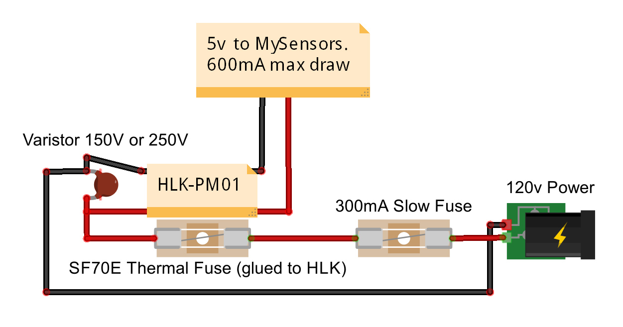
These are the parts I ordered. I haven't tested any of these parts yet as this project has been put on the back burner for now :(. I am in the USA so this is spec'd for 120 VAC. If you're using 240 you will need to change the size of the Varistor but everything else should be fine for 240.
Also, see these posts for more discussion/ideas if interested:
http://forum.mysensors.org/topic/1540/110v-230v-ac-to-mysensors-pcb-board
http://forum.mysensors.org/topic/2488/in-wall-pcbVaristor for 120VAC - http://www.ebay.com/itm/321024816822?_trksid=p2057872.m2749.l2649&ssPageName=STRK%3AMEBIDX%3AIT
73°C Thermal Fuse - http://www.ebay.com/itm/221560426284?_trksid=p2057872.m2749.l2649&var=520415979885&ssPageName=STRK%3AMEBIDX%3AIT
250V 300mA Slow Blow Fuse - http://www.ebay.com/itm/111433875797?_trksid=p2057872.m2749.l2649&var=410420838583&ssPageName=STRK%3AMEBIDX%3AIT
HLK-PM01 - http://www.ebay.com/itm/351418782712?_trksid=p2057872.m2749.l2649&ssPageName=STRK%3AMEBIDX%3AIT
Pete
@petewill Thank you very much for this excellent thread. It's great to see the community is in agreement on how to implement a safe power supply.
Just one comment; for 220V, shouldn't we opt for a lower amp rating fuse? If we stay with 300 mA, I am thinking we will not protect the device?
-
hmm have some questions too:
- is this setup only needed/recommended for in wall setups? or do you use this for all ac/dc converters?
- does someone has a picture for me to share, how this looks in reallive?
I'm not shure how to build my node in this case - what kind of cables (profile) do you use for the "high voltage" parts?
-
@nunver - A question i have also asked myself doing my PCB - i dont know if it makes any difference but HLK has a maximum imput of 200mA (1A spikes) according to its datasheet. What is the logic here and why - anyone that can explain?
@dakky I think this would be just as great for a outside ad/dc converter, the main idea is to protect us but in-wall you dont have the ability to remove the heat made from the HLK that easy. Pictures from my PCB here (Not completed) but based on this thread.
-
@petewill Thank you very much for this excellent thread. It's great to see the community is in agreement on how to implement a safe power supply.
Just one comment; for 220V, shouldn't we opt for a lower amp rating fuse? If we stay with 300 mA, I am thinking we will not protect the device?
@nunver I am by no means an expert in this (which is why I started the post :)) but it is my understanding that the fuses are there to protect your house (not sensor) from damage if something goes wrong. I can't remember where I read it but it was advised if the 300ma fuse blows the HLK should be replaced as a safety precaution.
is this setup only needed/recommended for in wall setups? or do you use this for all ac/dc converters?
So far I have always used phone chargers for all my sensors which haven't been in the wall. I have never had an issue. I use the phone chargers because I can usually get them free from work when they are recycled. The HLK is much smaller though so it's a great option.
I'm not shure how to build my node in this case what kind of cables (profile) do you use for the "high voltage" parts?
Good question. I'd be curious to hear what others are doing. I haven't had time to build an in-wall sensor yet but I was planning to use 14 gauge wire because that's what is in most of my house.