Which are the *best* NRF24L01+ modules?
-
@NeverDie Thanks, but it has quite some dependencies: Mirf, MirfHardwareSpiDriver & u8glib... I guess I have to strip it first.
Furthermore, which nrf24 library did you use? The one from tmrh20?@Yveaux said:
@NeverDie Thanks, but it has quite some dependencies: Mirf, MirfHardwareSpiDriver & u8glib...
Furthermore, which nrf24 library did you use? The one from tmrh20?Mirf is the nrf24 library. It's what the RFToy example used, so I started with it, because it "just worked" out of the box. It just happens to be as far as I've gotten so far. I haven't yet converted to tmrh20, which would look more familiar to you.
The start loop is just a left-over from when I was doing echo testing. I removed the OLED for this test because it was a potential source of interference, so any code related to that could be deleted. Obviously, most of the global variables aren't needed either. As far as transmitting once every 10ms, all the action happens in the main loop, which is pretty simple. It's all fairly basic, because up until I actually did it, I wasn't sure I could even get a sufficiently noiseless signal to measure. Luckily, running the RFtoy on a coincell, and because it's compact and without dangling wires, made that possible.
So, in terms of which library to install, at the moment the easiest would be to load the RFToy library.
Or you can wait until I convert over to tmrh20, and then you can follow along that way. I'll need to do that to do the sleep measurement, and because TMRH20 is currently the leading library to use--at least that's what ManiacBug seems to think.
Or, if you already know tmrh20, you could code it yourself. The pseudo-code is quite simple:
- Note the time in microseconds.
- Send a packet with a 4 byte data payload (i.e. a LONG)
- Wait until the current time exceeds the time in step 1 by at least 10,000 microseconds.
- Goto Step 1
What I don't know are the defaults for ACK's and # of retries, if any, in Mirf and in TMRH20. Aside from that possible difference, I would imagine the current draws are going to be the same in either library, wouldn't you?
Perhaps the cleanest thing would be to skip the libraries entirely and do it all purely by register manipulations. That'd probably be a diversion from where I want to go, but maybe not a huge diversion. After all, how hard could it be? Since the guys doing the mysensors library for the attiny85 appear to be stuck, I may eventually have to do it that way if I want to use an attiny85 (which I do).
-
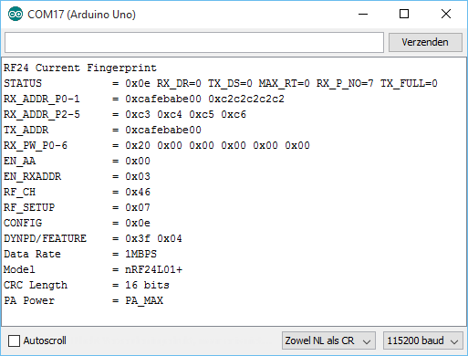
@NeverDIe I committed a small sketch + NRF24 library which should essentially do the same as your sketch.
Please find it at https://github.com/Yveaux/NRF24_CurrentFingerprint.
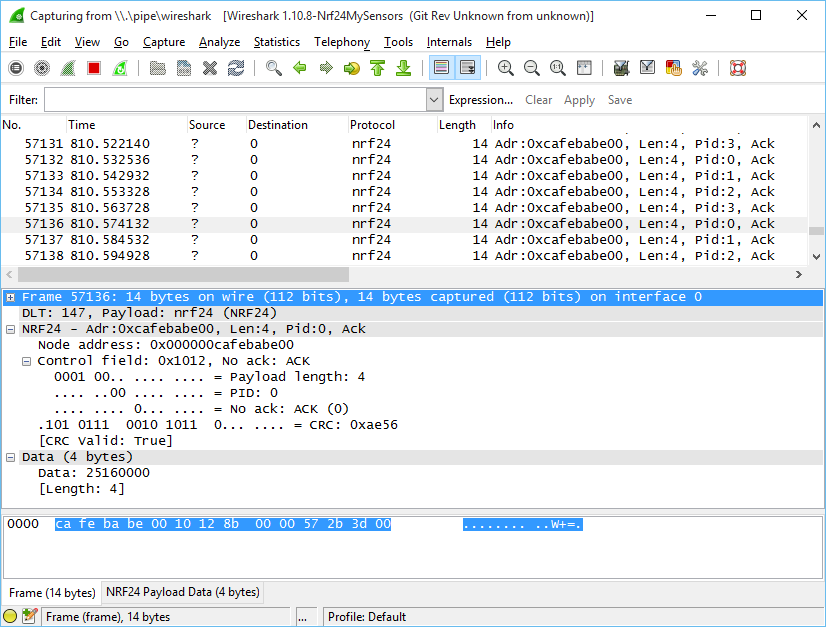
I verified its behavior using the NRF24 sniffer:Maybe we could compare register settings to be absolutely sure settings are identical:
Maybe you can repeat one of your measurements with this sketch, just to make sure we're measuring in the same way?
Currently I'm having a hard time measuring the actual current during transmit. I've not been able to get the individual spikes on the scope, not by using a uCurrent nor a single 1ohms resistor.
This is a uCurrent plot, set at 1mV/uA:
That boils down to 1.3mA peak during transmission... That can't be right?!
-
Small update: using a 10ohms resitor, the current profile looks like:
10mV/mA, so my module peaks at 11.7 mA. This module contains a 100% genuine Nordic nRF24L01+.
A module containing a proven fake nRF24L01+ (marked 1242AF), reveals following current profile:
This one peaks at 19.8mA !!
Register settings and on-air packets are identical.
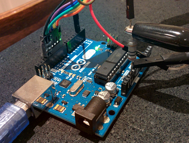
For completenes my measurement setup:
- Lab supply, which powers USB isolator
- USB isolator between PC & Arduino (otherwise ground-loops mess things up when using a USB scope on the same PC)
- 10 ohms resistor
-
That's great!
The red module I tested (above) also used 1242AF. So, asuming the NRF chip in the Itead is genuine (which seems increasingly likely), then proportionately speaking, we're getting similar measurements.
Aside from the Picoscope, what is your test setup? You don't seem to be experiencing the fat scope lines that I am. Where is the NRF module in your photo? Is it being levitated by the wires in the photo? I'm surprised the wires don't seem to be picking up noise.
@NeverDie I added it to my previous post.
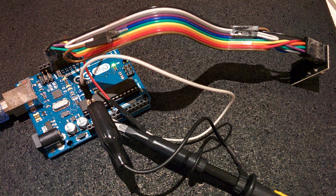
Overview of whole setup:
I never had issues with the wires picking up noise; at least not enough to distort communication. They're approx. 20cm long.
One more:
Module with nRF marked 1322DQ, supposedly genuine.
Also 11.2mATried it with another, random 1242AF, which gave 21.4mA
-
Exactly which USB isolator are you using? Sounds like I should get myself a couple in case I ever need to do this again.
@NeverDie A Chinese clone of this circuit: https://www.circuitsathome.com/measurements/usb-isolator
The power socket is used to power the isolated USB side.
Beware this isolator ca only handle FullSpeed (12MBit/s), so not USB 2.0 HighSpeed (480MBit/s).
This prevents me from isolating my USB scope with it... -
Your setup roughly resembles my first attempt, where I was also using an Uno. However, I was overwhelmed with noise, which made me try the RFToy. I wasn't using isolators, though. I'm glad you got yours working, because it means that just about anyone with isolators and a scope can maybe do this test for themselves. As illustrated by you, the setup if pretty easy to follow. Good job!
P.S. Does using ribbon cable, as you are doing, rather than individual Dupont wires (as I did when I tried using the Uno) also help with controlling noise?
-
Interestingly, the USB cable that came with my Rigol has big ferrite cores on both ends of it. So, that probably helps as well.
-
Actually, you could just power that arduino using a battery. Right? Having the isolator is nice, in that you can monitor what's happening, but not strictly necessary.
So, really, I guess anyone with an o-scope can do this test, which is great!
-
Actually, you could just power that arduino using a battery. Right? Having the isolator is nice, in that you can monitor what's happening, but not strictly necessary.
So, really, I guess anyone with an o-scope can do this test, which is great!
-
@NeverDie correct!
With some simple hardware the uno could measure the current by itself and determine the maximum current used!
This has potential! -
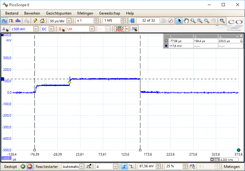
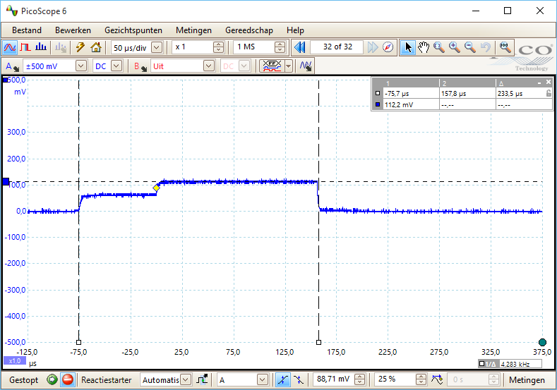
It turns out my scope can do better than I thought. Here's the blob module again, but this time at 5mv/div.
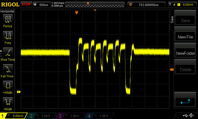
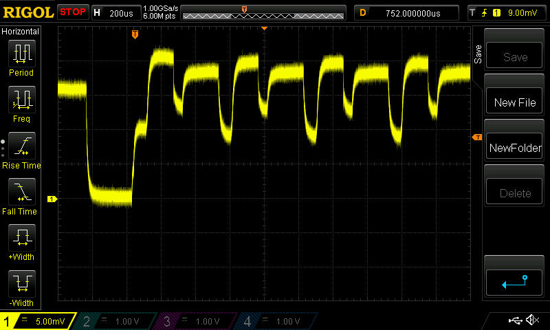
So, I may be able to use an even smaller resistor, because now I can go down to 1mv/div, whereas before it seemed it wouldn't let me go lower than 10mv/div. Hopefully that will help improve my measurement accuracy.
-
-
It turns out my scope can do better than I thought. Here's the blob module again, but this time at 5mv/div.
So, I may be able to use an even smaller resistor, because now I can go down to 1mv/div, whereas before it seemed it wouldn't let me go lower than 10mv/div. Hopefully that will help improve my measurement accuracy.
-
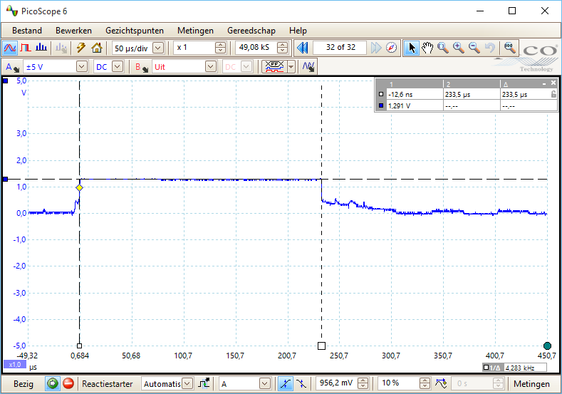
@NeverDie transmission takes 233us in my measurements. What's the hdiv on your scope? 500/200us?
-
-
@Yveaux said:
@NeverDie any chip. Transmission time if identical every time.
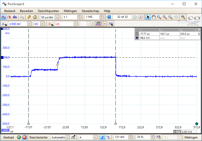
Here's my best picture of the start of the transmission cycle for the blob module. I'm not sure where to call the actual start of it though, but we need to agree on that if we're going to compare numbers without pictures.
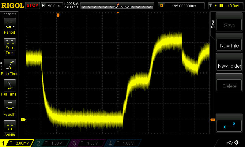
It's labeled on the upper bar (just to the right of the red "STOP") 50us/div
I modified the resister to be 1/2ohm, so now the vertical is 4ma/div, because it's 2mv/div vertical. Make sense? -
@Yveaux said:
@NeverDie any chip. Transmission time if identical every time.
Here's my best picture of the start of the transmission cycle for the blob module. I'm not sure where to call the actual start of it though, but we need to agree on that if we're going to compare numbers without pictures.
It's labeled on the upper bar (just to the right of the red "STOP") 50us/div
I modified the resister to be 1/2ohm, so now the vertical is 4ma/div, because it's 2mv/div vertical. Make sense?@NeverDie your horizontal scale is very different from what I measure.
The initial low-level part in the last scope picture shows only part of what you identify as transmission time, while it already lasts roughy 250us. That's more than the whole transmission time I measure!
We're definitely measuring differently.
Quickly off my head: a single message is 14 bytes long (see the sniffer capture above). At 1mbit this will take 14*8/1mbit=112 us. Add some time for startup, preamble, shutdown etc. and I think total time will be in the order of 233us, as I measured.Could you try running the sketch I put on github to compare things? Probably you will only have to change cs/ss pins to run it (I stick to the default mysensors connections)
It will also toggle a digital output on pin 3 before/after transmission which you can put on the scope together with the current measured, to have a reference when actual transmission takes place.Tonight (in 12 hours or so) I can do some more measurements if necessary.
-
I just now noticed where you put your markers on your o-scope plot. There are two voltage increases, the second settles out higher than the first, and it looks like you're counting both. I would guess transmission doesn't really start until the higher voltage is reached, though, wouldn't you? That also is a better match to your 112us number. Perhaps the lower voltage corresponds to loading the buffer or something like that that doesn't need the higher transmit power.
If you don't mind my asking, why the interest in the transmission length? Doesn't it have to be pretty similar from one type of chip to another, or else they won't interoperate?