Which are the *best* NRF24L01+ modules?
-
@Zeph: I'll may attempt those things tonight, though I'll be giving priority to moving over to TBRH20 first, as it will be better for comparisons if we minimize platform differences, as well as run the same library.
@NeverDie said:
@Zeph: I'll may attempt those things tonight, though I'll be giving priority to moving over to TBRH20 first, as it will be better for comparisons if we minimize platform differences, as well as run the same library.
I agree that using the same library is good for cross comparison among multiple experimenters.
However, if it turns out that the power profile differs between libraries, on the same hardware sending the same packet, that would be worth some investigation as well to understand why (and perhaps learn how to optimize power). Yeah, that's a different question than detecting variants and understanding their advantages/disadvantages, but the same measurement hardware can be used.
I was wondering if a small cap across your sense resistor might smooth the traces a bit, and still tell us what we want to know - which is about average power, on a multi-microsecond timescale.
-
Using a non-scientific method; looking at the angle of battery discharge graphs over a week, I've noticed that the modules I got from ITEAD are draining batteries at about half the rate compared to an unknown (but probably fake) pretty good module.
ITEAD module; slightly under 1% per day
"other modules"; about 2% per day
This is when measuring and transmitting DHT21 data every minute. -
@NeverDie said:
@Zeph: I'll may attempt those things tonight, though I'll be giving priority to moving over to TBRH20 first, as it will be better for comparisons if we minimize platform differences, as well as run the same library.
I agree that using the same library is good for cross comparison among multiple experimenters.
However, if it turns out that the power profile differs between libraries, on the same hardware sending the same packet, that would be worth some investigation as well to understand why (and perhaps learn how to optimize power). Yeah, that's a different question than detecting variants and understanding their advantages/disadvantages, but the same measurement hardware can be used.
I was wondering if a small cap across your sense resistor might smooth the traces a bit, and still tell us what we want to know - which is about average power, on a multi-microsecond timescale.
@Zeph said:
@NeverDie said:
@Zeph: I'll may attempt those things tonight, though I'll be giving priority to moving over to TBRH20 first, as it will be better for comparisons if we minimize platform differences, as well as run the same library.
I agree that using the same library is good for cross comparison among multiple experimenters.
However, if it turns out that the power profile differs between libraries, on the same hardware sending the same packet, that would be worth some investigation as well to understand why (and perhaps learn how to optimize power). Yeah, that's a different question than detecting variants and understanding their advantages/disadvantages, but the same measurement hardware can be used.
I was wondering if a small cap across your sense resistor might smooth the traces a bit, and still tell us what we want to know - which is about average power, on a multi-microsecond timescale.
Sounds plausible. What cap value would you suggest? I pretty much skipped over learning analog electronics and haven't yet found the time to backfill that gap in my knowledge.
I've been collecting on eevblog and elsewhere some seemingly good on-point advice about how to improve my scope captures in this situation. I'll probably learn one technique at a time, as time permits, and phase it in gradually.
-
I don't really know what a good value would be. Since it's across a 1 ohm resistor (in one case), and you probably want an RC time in the vicinity of microseconds, I'd start with around 1 uF and move up or down from there based on the scope trace. You may be able to just clamp the (short) leads of a cap to your probes to get a look, before soldering.
And I'll be interested in what other tips you collect that are useful.
-
Using a non-scientific method; looking at the angle of battery discharge graphs over a week, I've noticed that the modules I got from ITEAD are draining batteries at about half the rate compared to an unknown (but probably fake) pretty good module.
ITEAD module; slightly under 1% per day
"other modules"; about 2% per day
This is when measuring and transmitting DHT21 data every minute.@Stric said:
Using a non-scientific method; looking at the angle of battery discharge graphs over a week, I've noticed that the modules I got from ITEAD are draining batteries at about half the rate compared to an unknown (but probably fake) pretty good module.
ITEAD module; slightly under 1% per day
"other modules"; about 2% per day
This is when measuring and transmitting DHT21 data every minute.Good information. Hopefully, the scope will help sort out whether that faster drain is mostly during transmit/receive activity, or mostly during the idle time, or both.
-
I don't really know what a good value would be. Since it's across a 1 ohm resistor (in one case), and you probably want an RC time in the vicinity of microseconds, I'd start with around 1 uF and move up or down from there based on the scope trace. You may be able to just clamp the (short) leads of a cap to your probes to get a look, before soldering.
And I'll be interested in what other tips you collect that are useful.
@Zeph said:
I don't really know what a good value would be. Since it's across a 1 ohm resistor (in one case), and you probably want an RC time in the vicinity of microseconds, I'd start with around 1 uF and move up or down from there based on the scope trace. You may be able to just clamp the (short) leads of a cap to your probes to get a look, before soldering.
And I'll be interested in what other tips you collect that are useful.
Sounds good. We'll solve for the cap value using empiricism. :smile:
Also, I want to start measuring sleep current soon, because it may prove decisive as to whether a module must be rejected from further consideration because of its potential impact on battery life. Stric's data suggests there are significant differences to be found there. I suspect saving power is one of the harder engineering challenges--or, if not, at least an area where clones may get sloppy--and it might serve as a good separator.
-
Agreed. If the module takes more power during transmit because it's putting out more RF, we might be able to back it off by using less than the maximum power settings, or use it in applications where it more rarely transmits.
But if it uses too much sleep current, it's a bad option for battery power.
@Zeph said:
Agreed. If the module takes more power during transmit because it's putting out more RF, we might be able to back it off by using less than the maximum power settings, or use it in applications where it more rarely transmits.
But if it uses too much sleep current, it's a bad option for battery power.
Exactly! You said it better than I did.
-
For further comparison, here are the measurements taken on the red module from earlier in the thread:
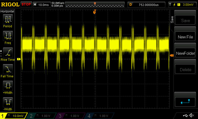
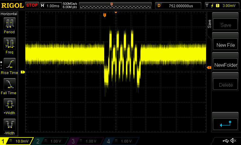
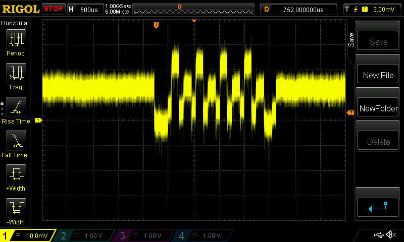
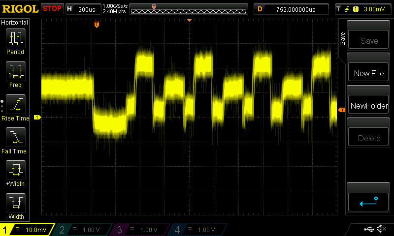
Again, just eyeballing it, that looks like, what, maybe 23ma? Acually more than the blob module, it would seem.
-
I hooked up the uCurrent inline with the Itead NRF24L01+ module, measured using a Fluke 87V multimeter, and I got these measurements:
Powered Down (Sleep): 0.6uA
Standby: 22.6uAI'm satisfied that these are within error tolerances for the expected results.
Prior to that, I tested the blob module and seemed to get bizarre results. I'm going to go back and re-test now that I'm reasonably confident the test setup and measurements are working right.
I'm using an Arduino Uno. This was the test code I used:
/* Adapted by NeverDie on 8/11/2015 to facilitate uCurrent measurements. /* Copyright (C) 2011 J. Coliz <maniacbug@ymail.com> This program is free software; you can redistribute it and/or modify it under the terms of the GNU General Public License version 2 as published by the Free Software Foundation. TMRh20 2014 - Updates to the library allow sleeping both in TX and RX modes: TX Mode: The radio can be powered down (.9uA current) and the Arduino slept using the watchdog timer RX Mode: The radio can be left in standby mode (22uA current) and the Arduino slept using an interrupt pin */ /** * Example RF Radio Ping Pair which Sleeps between Sends * * This is an example of how to use the RF24 class to create a battery- * efficient system. It is just like the GettingStarted_CallResponse example, but the * ping node powers down the radio and sleeps the MCU after every * ping/pong cycle, and the receiver sleeps between payloads. * * Write this sketch to two different nodes, * connect the role_pin to ground on one. The ping node sends the current * time to the pong node, which responds by sending the value back. The ping * node can then see how long the whole cycle took. */ #include <SPI.h> #include <avr/sleep.h> #include <avr/power.h> #include "nRF24L01.h" #include "RF24.h" #include "printf.h" // Set up nRF24L01 radio on SPI bus plus pins 7 & 8 RF24 radio(7,8); // sets the role of this unit in hardware. Connect to GND to be the 'pong' receiver // Leave open to be the 'ping' transmitter const int role_pin = 5; const uint64_t pipes[2] = { 0xF0F0F0F0E1LL, 0xF0F0F0F0D2LL }; // Radio pipe addresses for the 2 nodes to communicate. // Role management // Set up role. This sketch uses the same software for all the nodes // in this system. Doing so greatly simplifies testing. The hardware itself specifies // which node it is. // The various roles supported by this sketch typedef enum { role_ping_out = 1, role_pong_back } role_e; // The debug-friendly names of those roles const char* role_friendly_name[] = { "invalid", "Ping out", "Pong back"}; // The role of the current running sketch role_e role; void setup(){ // set up the role pin pinMode(role_pin, INPUT); digitalWrite(role_pin,HIGH); delay(20); // Just to get a solid reading on the role pin // read the address pin, establish our role if ( digitalRead(role_pin) ) role = role_ping_out; else role = role_pong_back; Serial.begin(57600); printf_begin(); printf("\n\rRF24/examples/pingpair_sleepy/\n\r"); printf("ROLE: %s\n\r",role_friendly_name[role]); radio.begin(); // Open pipes to other nodes for communication // This simple sketch opens two pipes for these two nodes to communicate // back and forth. // Open 'our' pipe for writing // Open the 'other' pipe for reading, in position #1 (we can have up to 5 pipes open for reading) if ( role == role_ping_out ) { radio.openWritingPipe(pipes[0]); radio.openReadingPipe(1,pipes[1]); } else { radio.openWritingPipe(pipes[1]); radio.openReadingPipe(1,pipes[0]); } // Dump the configuration of the rf unit for debugging radio.printDetails(); } void loop(){ radio.powerDown(); // NOTE: The radio MUST be powered back up again manually delay(5000); radio.powerUp(); // Power up the radio after sleeping delay(5000); } -
Yup, same as before. The measurements on the blob module are:
-43.3ua and -42.8ua.I'm not sure which is standby current and which is sleep current. I definitely was not expecting a negative current. There's not much difference in magnitude between the two currents.
So, I tried it on a different blob module:
-43.5ua and -42.9ua.
Essentially the same results.Truly bizarre. What's going on? I'm powering the Uno through a roughly 9V battery pack of Eneloop batteries via its barrel jack, as with the earlier measurement of the Itead module, whose measurements not only met expected value, but they were positive currents, not negative ones.
Here's the red module:
Powered Down (Sleep): 1.6uA
Standby: 13.9uAHere's an Addicore module from Amazon:
Powered Down (Sleep): 1.8uA
Standyby: 16.3uAIt's a very simple test. I'd say anyone can do these measurements, provided they have a good way to measure microamps.
-
@NeverDie said:
-43.3ua and -42.8ua.
So the blob module is so good that it is charging your batteries ;-)
@rvendrame said:
@NeverDie said:
-43.3ua and -42.8ua.
So the blob module is so good that it is charging your batteries ;-)
I'm measuring the current between the Uno 3.3 Female header pin and the Vcc pin on the RF module.
-
Now talking seriously, maybe the some current is leaking through the other pins (MISO, CE, CS, etc), from arduino to radio? That would could an negative VCC flow I think...
-
It must be that. I wonder how it would measure if I were to use 3.3v on the datapins rather than the 5v the Uno uses.
-
In theory it would require a logic level converter
But for sure the atmega is tolerant between 3.3V and 5V. And probably the converter would introduce an error in the u-measurement, I guess.
-
I plugged a blob module into the RFToy, which is effectively an 8Mhz Mini Pro running at 3.3v, and used a jig similar to the one before (just no resistor) to route the module Vcc current into the uCurrent.
This time it is powered through the USB port, and the voltage is downshifted from there.
New measurements for the blob module:
Powered Down (Sleep): 3.3uA
Standby: 67.2uAFor comparison, I plugged the Itead module (Nordic tracecode 1301CL) into the same apparatus, and this time I got
Powered Down (Sleep): 0.6uA
Standby: 22.8uA
which, within measurement error, I would call the same as when it was hooked up to the Uno. -
@Zeph: For the NRF24L01+ modules, I now have good enough current measurements that I wanted to get, so I'll be holding off on doing further measurements, at least for now. I want to try the RFM69HW for comparison, but that is outside the scope of this thread.
-
BTW, using just my Fluke 87V multimeter set on the uA setting, the measurements I get are:
Fluke 87V Itead Module Measurements:
Powered Down(Sleep): 0.5uA
Standby: 22.5uAand
Fluke 87V Blob Module Meaasurements:
Powwred Down(Sleep): 3.0uA
Standby: 56uAand
Fluke 87V Addicore module from Amazon Measurements:
Powered Down: 1.2uA
Standby: 18.2uASo, although a bit different than the uCurrent measurements, they seem good enough for separating out the fakes that I have from the genuine article (which at this point the evidence suggests is what the chip in the Itead module is).
So, good news! Maybe all you need is a DMM with decent uA measurements. If I'd had this information at the very beginning of this thread, it would have saved me a lot of frustration and doubt. Now everyone can be empowered. :smile: The next time you buy modules, you can now easily test them right away and send them back if they're fake! :smile: :smile: :smile: