Battery Sensor v 1.0 PCB
-
I've found what may be the first problem with this unit. I have a combination temp/humidity/light sensor running on it, a known good sketch that works on other hardware. I added battery measurement support to it and it appears to work fine.
This morning I noticed it had not updated Vera since 11:20 last night. This is the second time I've seen this so far but each time I start working on debugging it seems to start working. The common element is that it was sitting on a window sill in the kitchen so I could get easy access to measure the battery voltage and when I debug its on a counter in the family room. The difference is the kitchen is about 15 feet further away from the gateway! The path is no more obstructed in either room, there is essentially one wall between the gateway and the sensor remote.
I have a scramble-wired 5v version running for test and it reports everywhere in the house. The PCB version fails in the bedroom, again about 20 feet further from the gateway than the family room. I've changed radios so it doesn't appear to be just a weak radio.
I have a good solid 3.3V on the radio Vcc so it isn't a voltage drop problem. I'm wondering if there is a problem with the radio sitting over the PCB ground plane. I have one of the Seeed Studio DevDuino v 2.0 units an the radio also sits over the ground plane on that device. I haven't gotten around to programming it yet so I can't compare the performance.
I'm also trying a radio with the external SMA antenna and found that, as one might expect, it works at considerable distance, in this case over 100 feet down the street, through the concrete block external house walls.
I removed the radio from the PCB socket and put it on a cable about 8 inches long to get away from the ground plane and that does NOT appear to have made any difference. However, if I hold the unit up over my head at arms length the gateway does get the update.
Can anyone comment on your experience with the basic NRF24L01 radio modules in terms of range from the gateway, obstructions in the path, etc. Any opinion on the likelihood of a ground plane problem?
Also FYI, I've been monitoring the battery voltage externally and in the past 36 hours the battery voltage has dropped 0.04v. This is without making any changes to reduce drain such as cutting the LEDs, using the Low Power Library, etc. I expect that running the LP library and making the other changes, the CR123 should have excellent battery life.
@clippermiami said:
I have a good solid 3.3V on the radio Vcc so it isn't a voltage drop problem. I'm wondering if there is a problem with the radio sitting over the PCB ground plane. I have one of the Seeed Studio DevDuino v 2.0 units an the radio also sits over the ground plane on that device. I haven't gotten around to programming it yet so I can't compare the performance.
I think problem could be on the step-up regulator. It as been reported some regulators behave badly on nrf24 peak/burst operation.
On those moments instant current needs are above normal and the VCCout from the regulator oscillates terribly.As a test, please use the capacitor workaround and check if problem still occurs.
-
@clippermiami said:
I have a good solid 3.3V on the radio Vcc so it isn't a voltage drop problem. I'm wondering if there is a problem with the radio sitting over the PCB ground plane. I have one of the Seeed Studio DevDuino v 2.0 units an the radio also sits over the ground plane on that device. I haven't gotten around to programming it yet so I can't compare the performance.
I think problem could be on the step-up regulator. It as been reported some regulators behave badly on nrf24 peak/burst operation.
On those moments instant current needs are above normal and the VCCout from the regulator oscillates terribly.As a test, please use the capacitor workaround and check if problem still occurs.
@BSoft Thanks. I'll try jumping around the up-regulator and see if that helps
-
@BSoft Thanks. I'll try jumping around the up-regulator and see if that helps
@clippermiami
You can still use the step-up, connect the capacitor in parallel between VCCout (regulator) and ground.Or better, connect the capacitor between VCC-GND on the NRF24 (the closest you get to nRF24 is better).
If you still get transmission problems and if possible, bypass the step-up and keep the capacitor on and check again.
-
@clippermiami said:
I have a good solid 3.3V on the radio Vcc so it isn't a voltage drop problem. I'm wondering if there is a problem with the radio sitting over the PCB ground plane. I have one of the Seeed Studio DevDuino v 2.0 units an the radio also sits over the ground plane on that device. I haven't gotten around to programming it yet so I can't compare the performance.
I think problem could be on the step-up regulator. It as been reported some regulators behave badly on nrf24 peak/burst operation.
On those moments instant current needs are above normal and the VCCout from the regulator oscillates terribly.As a test, please use the capacitor workaround and check if problem still occurs.
@BSoft I jumpered around the up-regulator and it didn't make any difference, I still cannot get updates from the kitchen, about 30 feet and one wall from the gateway. So far the only thing that has made a difference is the NRF with the SMA antenna.
-
@clippermiami
You can still use the step-up, connect the capacitor in parallel between VCCout (regulator) and ground.Or better, connect the capacitor between VCC-GND on the NRF24 (the closest you get to nRF24 is better).
If you still get transmission problems and if possible, bypass the step-up and keep the capacitor on and check again.
@BSoft re: Capacitor Bypass. I assume you are talking about the 4.7uFd cap between the Vcc and Gnd on the radio? If so its been installed from the get-go, its part of the design and is within millimeters of the NRF connector.
-
Ok, since sma antenna is more power demanding and works ok, maybe capacitor isn't solution.
But i get better than 30 feet on zigzag antenna, maybe you have a not so perfect pcb unit (nRF). It is nice and residue clean?
@BSoft I've tried several different ones, theyt all look clean, no "gunk" or anything. I even tried taking it off the board and putting it on a extension cable, same results.Yeah, 30 feet seems a bit of a drag :)
john
-
@BSoft re: Capacitor Bypass. I assume you are talking about the 4.7uFd cap between the Vcc and Gnd on the radio? If so its been installed from the get-go, its part of the design and is within millimeters of the NRF connector.
@clippermiami said:
@BSoft re: Capacitor Bypass. I assume you are talking about the 4.7uFd cap between the Vcc and Gnd on the radio? If so its been installed from the get-go, its part of the design and is within millimeters of the NRF connector.
Yes it is!
Sorry i wasn't aware of 4.7uF presence.
You could add more since it as been reported as better (220µF), check here: link text
-
@clippermiami said:
@BSoft re: Capacitor Bypass. I assume you are talking about the 4.7uFd cap between the Vcc and Gnd on the radio? If so its been installed from the get-go, its part of the design and is within millimeters of the NRF connector.
Yes it is!
Sorry i wasn't aware of 4.7uF presence.
You could add more since it as been reported as better (220µF), check here: link text
@BSoft Interesting discussion. Bottom line seem to be that 4.7 uF doesn't do much, the more the merrier then.
-
It's not just about capacity, it's about using a capacitor with low ESR.
-
Are you trying different orientations of the antenna? While I've not seen any spec's for the cheap module antenna ("7" shape or zigzag), I think I recall seeing reference to a pattern with two peak lobes and two nulls for another nRF24L01+ or nRF51822 based module. It's unlikely that the antenna is omnidirectional. (I don't know if the antenna also has polarization issues, another possibility).
@Zeph I changed orientation buy door of "incidentally" , I held the unit up over my head to see if I got updates and I did, more often than just sitting on the counter but still not all the time. In this case the antennas would have been vertical rather than horizontal. Puzzling to be sure.
-
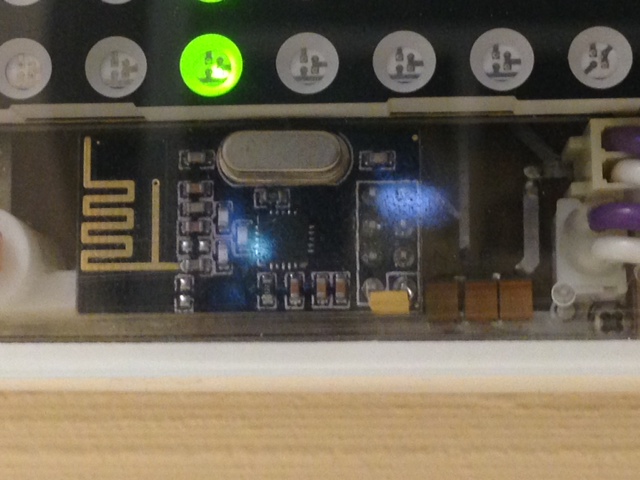
about capacitor for radio. Attached you can see picture from one of my successful project
capacitor is tantalum 22uF soldered directly to pins of the module, from the side of module PCB
you can see capacitor as a small yellow box on top of the 8 pin radio connector
sense and drive
-
about capacitor for radio. Attached you can see picture from one of my successful project
capacitor is tantalum 22uF soldered directly to pins of the module, from the side of module PCB
you can see capacitor as a small yellow box on top of the 8 pin radio connector
@axillent Do you have a feel for the range of this rig? If this is the answer I'll get the capacitor and mod every radio :)
My Gateway has the SMA antenna on it and is less than 30 feet, and one interior wall, from the sensor and it doesn't work. When I bring the sensor to within about 10-12 feet it works every time but out at 20+ feet it fails almost every time. Its hard to believe that there is so little range
I've tried a number of things:
(a) several different radios - no change
(b) remove the radio and place it on a 8 inch cable to get away from the ground plane - no change;
(c) jumpered around the up-regulator (i.e. everything direct connected to battery) - no change;
(d) radio with SMA antenna - works every time but the battery consumption goes through the roof. In 12 hours with the SMA antenna the battery dropped 0.12 V versus 0.04 V in 24 hours with the regular radio. The AMP on the antenna version consumes a lot of juice.Puzzlement :)
-
@axillent Do you have a feel for the range of this rig? If this is the answer I'll get the capacitor and mod every radio :)
My Gateway has the SMA antenna on it and is less than 30 feet, and one interior wall, from the sensor and it doesn't work. When I bring the sensor to within about 10-12 feet it works every time but out at 20+ feet it fails almost every time. Its hard to believe that there is so little range
I've tried a number of things:
(a) several different radios - no change
(b) remove the radio and place it on a 8 inch cable to get away from the ground plane - no change;
(c) jumpered around the up-regulator (i.e. everything direct connected to battery) - no change;
(d) radio with SMA antenna - works every time but the battery consumption goes through the roof. In 12 hours with the SMA antenna the battery dropped 0.12 V versus 0.04 V in 24 hours with the regular radio. The AMP on the antenna version consumes a lot of juice.Puzzlement :)
@clippermiami My distances are not too long, Just measured - this particular device is ranged 5m with one wall on the way to gateway
you have to distinguish radio with SMA **without **PA&LNA and radio **with **SMA and with PA&LNA
last one have an additional chip to amplify radio signal both wayradio without PA & LNA with SMA can sometimes be worse comparing to radio with PCB antenna
it depends on how well external antenna is aligned by frequency and impedanceList of your actions have radio channel tuning missed
sense and drive
-
@clippermiami My distances are not too long, Just measured - this particular device is ranged 5m with one wall on the way to gateway
you have to distinguish radio with SMA **without **PA&LNA and radio **with **SMA and with PA&LNA
last one have an additional chip to amplify radio signal both wayradio without PA & LNA with SMA can sometimes be worse comparing to radio with PCB antenna
it depends on how well external antenna is aligned by frequency and impedanceList of your actions have radio channel tuning missed
@axillent This SMA unit has the PA on it. The radio channel is the default for everything.
You distance is similar to mine, about 4.5-5 meters with one wall and it works. Beyond that NADA :)
-
@axillent This SMA unit has the PA on it. The radio channel is the default for everything.
You distance is similar to mine, about 4.5-5 meters with one wall and it works. Beyond that NADA :)
@clippermiami said:
@axillent This SMA unit has the PA on it. The radio channel is the default for everything.
works and works the best way are different things, If you live far from big cities probably it make no sense.
Otherwise it is recommended to run network scan from RF24 examples to find less busy channel at your location.sense and drive
-
@clippermiami said:
@axillent This SMA unit has the PA on it. The radio channel is the default for everything.
works and works the best way are different things, If you live far from big cities probably it make no sense.
Otherwise it is recommended to run network scan from RF24 examples to find less busy channel at your location.@axillent The wireless channel is the one thing I hadn't investigated as yet so i will. I suppose it could be congested around here.
-
I ran the scanner but got page after page of:
     RF24/examples/scanner/

     Scanning all available frequencies...Scan completed.
     Scanning all available frequencies...Scan completed.
     Scanning all available frequencies...Scan completed.
     Scanning all available frequencies...Scan completed.
My radio is configured exactly as described although I will admit i just loaded the sketch to the sensor board and ran it on there rather than set up a special build just for that.
: -
I ran the scanner but got page after page of:
     RF24/examples/scanner/

     Scanning all available frequencies...Scan completed.
     Scanning all available frequencies...Scan completed.
     Scanning all available frequencies...Scan completed.
     Scanning all available frequencies...Scan completed.
My radio is configured exactly as described although I will admit i just loaded the sketch to the sensor board and ran it on there rather than set up a special build just for that.
:@clippermiami do not knew why but there are a few versions of this example
try this onesorry, do not knew how to insert a code here
/*
 Copyright (C) 2011 James Coliz, Jr. <maniacbug@ymail.com>
 Copyright (c) 2012 Greg Copeland

 This program is free software; you can redistribute it and/or
 modify it under the terms of the GNU General Public License
 version 2 as published by the Free Software Foundation.
 */

/**
 * Channel scanner
 *
 * Example to detect interference on the various channels available.
 * This is a good diagnostic tool to check whether you're picking a
 * good channel for your application.
 *
 * Inspired by cpixip.
 * See http://arduino.cc/forum/index.php/topic,54795.0.html
 */

#include <SPI.h>
#include "RF24.h"
#include "printf.h"

// Only display active frequencies
static const bool activeOnly = true ;

//
// Hardware configuration
//

// Set up nRF24L01 radio on SPI bus plus pins 8 & 9

RF24 radio(9,10);

//
// Channel info
//

const short num_channels = 128;
short values[num_channels];
uint8_t signalMeter[55] ;

//
// Setup
//

void setup(void)
{
  //
  // Print preamble
  //

  Serial.begin(115200);
  printf_begin();
  printf("\n\rRF24/examples/scanner/\n\r");

  //
  // Setup and configure rf radio
  //

  radio.begin();
  radio.powerUp() ;
  radio.setAutoAck(false);

  // Get into standby mode
  radio.openReadingPipe( 0, 0xFFFFFFFFFFULL ) ;
  //  radio.setDataRate( RF24_250KBPS ) ; // may fallback to 1Mbps
  radio.setDataRate( RF24_1MBPS ) ; // may fallback to 1Mbps
  radio.startListening() ;
  radio.stopListening() ;
}

//
// Loop
//
void loop(void)
{
  // Clear measurement values
  memset( values, 0x00, num_channels ) ;
  printf( "Scanning all available frequencies..." ) ;

  // Repeatedly scan multiple channels
  for( int channel=0 ; channel < num_channels; channel++ ) {
    radio.setChannel( channel ) ;

    // Amplify the signal based on carrier bandwidth
    int ampFactor ;
    for( int amp=0; amp <= 300; amp++ ) {
      // Alternate data rates
      ampFactor = amp%3 ;
      switch( ampFactor ) {
      case 0:
	radio.setDataRate( RF24_250KBPS ) ;
	break ;

      case 1:
	radio.setDataRate( RF24_1MBPS ) ;
	break ;

      default:
	radio.setDataRate( RF24_2MBPS ) ;
	break ;
      }

      // Listen for carrier
      ampFactor++ ;
      radio.startListening() ;
      delayMicroseconds( 6 - ampFactor ) ;
      radio.stopListening() ;

      // Was carrier detected? If so, signal level based on bandwidth
      if( radio.testRPD() ) {
	values[channel] += ampFactor ;
      }
    }
  }

  // Now display our results
  printf( "Scan completed.\r\n" ) ;
  for( int channel=0 ; channel < num_channels; channel++ ) {
    if( !activeOnly || (activeOnly && values[channel] > 0) ) {
      memset( signalMeter, '*', min( values[channel], 54 ) ) ;
      signalMeter[min(values[channel], 54)] = 0x00 ;
      printf( "%03d (%4dMhz): %02d - %s\r\n",
	      channel,
	      2400+channel,
	      values[channel],
	      signalMeter ) ;

      // Reset the scanned value since its already beend displayed
      values[channel] = 0 ;
    }
  }
}

// vim:ai:cin:sts=2 sw=2 ft=cpp
sense and drive