Battery Sensor v 1.0 PCB
-
Previously I reported that I was working on developing a PCB for battery operated sensors to meet the following criteria:
- Powered by CR123 3v Lithium Battery
- 0.8v > 3.3v converter/regulator for max battery life
- Support for 2@ Digital, 2@ Analog, 1@ L2C interface
- Screw terminal blocks for sensor attachment
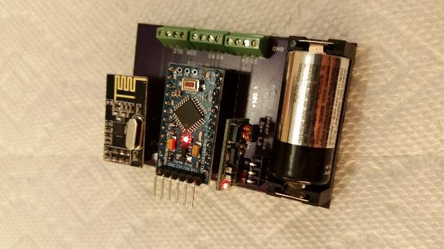
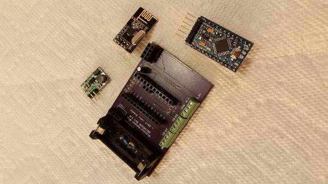
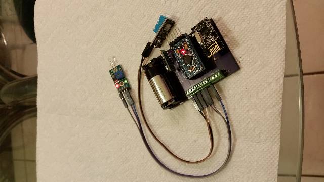
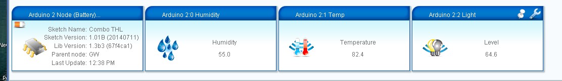
The v1.0 PCB came back from OSHPark yesterday and I've installed all the parts and loaded a known working Temp/Humidity/Light sketch with the addition of the battery level reporting as described on My Sensors.
I'm pleased to report that it installed and operated the first time and my VeraLite located and included it without a problem. I do have a problem with the battery voltage information and suspect I swapped the 1M Ohm and 470K Ohm resistors the voltage divider.
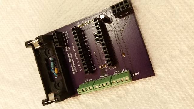
It's a very spacious board ... for my first attempt at Eagle and PCB design and creation I chose not to try to conserve real estate but rather give myself plenty of room to work. I also have a minor component placement problem with the space allocated for the voltage divider resistors.
I'm considering a version 2.0 board to correct the few errors and to include some other functions to make the board more general purpose battery or external power:
- 2.1mm barrel connector and 7805 regulator for external power
- 1v > 5v converter to allow 5v sensors on the battery version
- 5 pin screw terminal blocks to support both 3.3 and 5 v sensors on any version
I will make the current v 1.0 version available on OSHPark if anyone is interested.
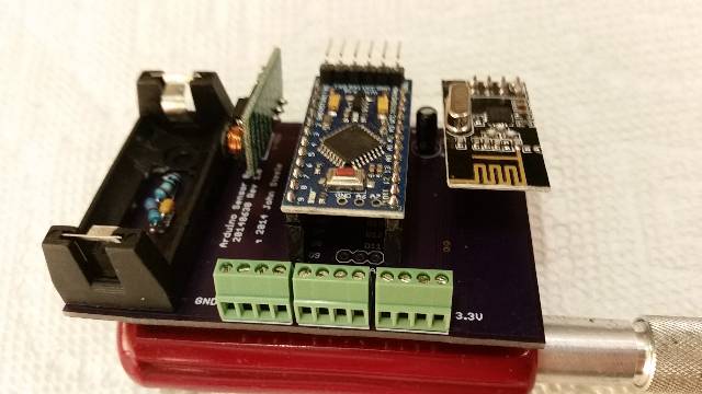
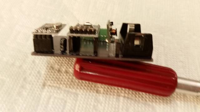
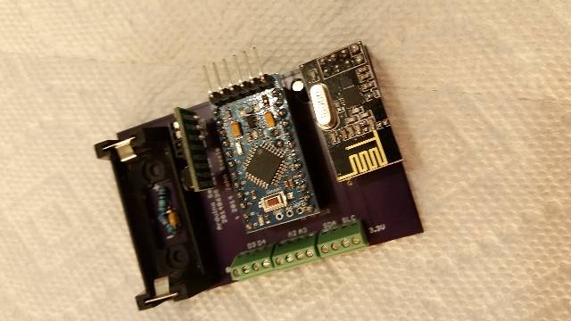
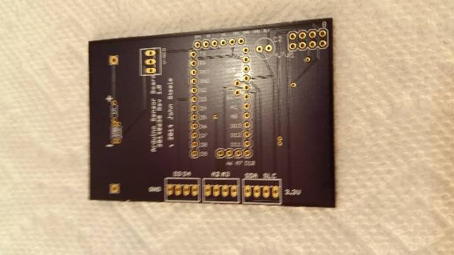
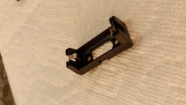
I have attached some photos of the board, components and the assembly. Everything is in sockets for this test but in production I'd probably solder the subassemblies directly to the board
-
Previously I reported that I was working on developing a PCB for battery operated sensors to meet the following criteria:
- Powered by CR123 3v Lithium Battery
- 0.8v > 3.3v converter/regulator for max battery life
- Support for 2@ Digital, 2@ Analog, 1@ L2C interface
- Screw terminal blocks for sensor attachment
The v1.0 PCB came back from OSHPark yesterday and I've installed all the parts and loaded a known working Temp/Humidity/Light sketch with the addition of the battery level reporting as described on My Sensors.
I'm pleased to report that it installed and operated the first time and my VeraLite located and included it without a problem. I do have a problem with the battery voltage information and suspect I swapped the 1M Ohm and 470K Ohm resistors the voltage divider.
It's a very spacious board ... for my first attempt at Eagle and PCB design and creation I chose not to try to conserve real estate but rather give myself plenty of room to work. I also have a minor component placement problem with the space allocated for the voltage divider resistors.
I'm considering a version 2.0 board to correct the few errors and to include some other functions to make the board more general purpose battery or external power:
- 2.1mm barrel connector and 7805 regulator for external power
- 1v > 5v converter to allow 5v sensors on the battery version
- 5 pin screw terminal blocks to support both 3.3 and 5 v sensors on any version
I will make the current v 1.0 version available on OSHPark if anyone is interested.
I have attached some photos of the board, components and the assembly. Everything is in sockets for this test but in production I'd probably solder the subassemblies directly to the board
-
@clippermiami Ah, there are the images ;-)
Very nice and spacious indeed!
Why did you decice to bring the 3V from the bttery to 3.3V? Do you need a stable supply for sensors?@Yveaux Well, it just seemed to make sense. The CR123 is a 3V battery and the Arduino is 3.3V for a starter. And the upconverter/regulator allows 3.3v out from a battery input as low as 0.8v so I thought that would help extract as much juice a possible from the battery.
John
-
@Yveaux Well, it just seemed to make sense. The CR123 is a 3V battery and the Arduino is 3.3V for a starter. And the upconverter/regulator allows 3.3v out from a battery input as low as 0.8v so I thought that would help extract as much juice a possible from the battery.
John
@clippermiami There's another discussion going on here about regulating to 3v3 from batteries. The Arduino & RF24 will still run fine if voltage drops, and it saves you the loss of the regulator.
Anyway, just start it up and see how long the battery will last! -
Previously I reported that I was working on developing a PCB for battery operated sensors to meet the following criteria:
- Powered by CR123 3v Lithium Battery
- 0.8v > 3.3v converter/regulator for max battery life
- Support for 2@ Digital, 2@ Analog, 1@ L2C interface
- Screw terminal blocks for sensor attachment
The v1.0 PCB came back from OSHPark yesterday and I've installed all the parts and loaded a known working Temp/Humidity/Light sketch with the addition of the battery level reporting as described on My Sensors.
I'm pleased to report that it installed and operated the first time and my VeraLite located and included it without a problem. I do have a problem with the battery voltage information and suspect I swapped the 1M Ohm and 470K Ohm resistors the voltage divider.
It's a very spacious board ... for my first attempt at Eagle and PCB design and creation I chose not to try to conserve real estate but rather give myself plenty of room to work. I also have a minor component placement problem with the space allocated for the voltage divider resistors.
I'm considering a version 2.0 board to correct the few errors and to include some other functions to make the board more general purpose battery or external power:
- 2.1mm barrel connector and 7805 regulator for external power
- 1v > 5v converter to allow 5v sensors on the battery version
- 5 pin screw terminal blocks to support both 3.3 and 5 v sensors on any version
I will make the current v 1.0 version available on OSHPark if anyone is interested.
I have attached some photos of the board, components and the assembly. Everything is in sockets for this test but in production I'd probably solder the subassemblies directly to the board
-
@clippermiami nice work!
which IC is used for step-up?@axillent I used the module listed on the Store (http://www.ebay.com/itm/231083181020) so I don't know the details.
-
If anyone is interested the board is shared on OSHPark under my UserName "ClipperMiami" as
-
Previously I reported that I was working on developing a PCB for battery operated sensors to meet the following criteria:
- Powered by CR123 3v Lithium Battery
- 0.8v > 3.3v converter/regulator for max battery life
- Support for 2@ Digital, 2@ Analog, 1@ L2C interface
- Screw terminal blocks for sensor attachment
The v1.0 PCB came back from OSHPark yesterday and I've installed all the parts and loaded a known working Temp/Humidity/Light sketch with the addition of the battery level reporting as described on My Sensors.
I'm pleased to report that it installed and operated the first time and my VeraLite located and included it without a problem. I do have a problem with the battery voltage information and suspect I swapped the 1M Ohm and 470K Ohm resistors the voltage divider.
It's a very spacious board ... for my first attempt at Eagle and PCB design and creation I chose not to try to conserve real estate but rather give myself plenty of room to work. I also have a minor component placement problem with the space allocated for the voltage divider resistors.
I'm considering a version 2.0 board to correct the few errors and to include some other functions to make the board more general purpose battery or external power:
- 2.1mm barrel connector and 7805 regulator for external power
- 1v > 5v converter to allow 5v sensors on the battery version
- 5 pin screw terminal blocks to support both 3.3 and 5 v sensors on any version
I will make the current v 1.0 version available on OSHPark if anyone is interested.
I have attached some photos of the board, components and the assembly. Everything is in sockets for this test but in production I'd probably solder the subassemblies directly to the board
-
Nice work!!! I would avoid the step-up module... for a low discharge scenario CR123 give us almost all juice with their voltage up to 1.9V (nRF24L01 limit).
@BSoft Interesting point. That would simplify things a bit :)
-
@BSoft Interesting point. That would simplify things a bit :)
-
You will have to disable BOD fuses if you want to work below 2.4V.
Please also take in account that using atmega328p below 2.4V will decrease operational frequency (below 8MHz).
More details at this post: link text
I still prefer to avoid any type of regulators.
-
With a 4 MHz crystal it can run to near 1V8. See page 310 of the data sheet.
The radio could run directly off the battery and the CPU and sensors off the inverter. That may be a good compromise as the radio draws the most amount of power?
@a-lurker said:
With a 4 MHz crystal it can run to near 1V8. See page 310 of the data sheet.
crystal also need some power to operate
running without crystal can help
with mysensors battery board we decided to not use crystal
MCU will run from internal RC 8MHz with CLDIV8 enabled
etc. basic frequency 1MHz with ability to speed up to 8MHz on the flyThe radio could run directly off the battery and the CPU and sensors off the inverter. That may be a good compromise as the radio draws the most amount of power?
radio draws about 12mA at time of receive/transmit
but while you thinking about battery life it is important to think not about current draw, but about power consumed
the power is a function of current multiplied by timein this logic for example DS18B20 is very power consuming, because it needs a few mA for 750ms
radio consumed 12mA but for shorter time
MCU consumes less but for much longer time, and you need to understand it's average current consumption through the circle between sleep and active modes -
I've found what may be the first problem with this unit. I have a combination temp/humidity/light sensor running on it, a known good sketch that works on other hardware. I added battery measurement support to it and it appears to work fine.
This morning I noticed it had not updated Vera since 11:20 last night. This is the second time I've seen this so far but each time I start working on debugging it seems to start working. The common element is that it was sitting on a window sill in the kitchen so I could get easy access to measure the battery voltage and when I debug its on a counter in the family room. The difference is the kitchen is about 15 feet further away from the gateway! The path is no more obstructed in either room, there is essentially one wall between the gateway and the sensor remote.
I have a scramble-wired 5v version running for test and it reports everywhere in the house. The PCB version fails in the bedroom, again about 20 feet further from the gateway than the family room. I've changed radios so it doesn't appear to be just a weak radio.
I have a good solid 3.3V on the radio Vcc so it isn't a voltage drop problem. I'm wondering if there is a problem with the radio sitting over the PCB ground plane. I have one of the Seeed Studio DevDuino v 2.0 units an the radio also sits over the ground plane on that device. I haven't gotten around to programming it yet so I can't compare the performance.
I'm also trying a radio with the external SMA antenna and found that, as one might expect, it works at considerable distance, in this case over 100 feet down the street, through the concrete block external house walls.
I removed the radio from the PCB socket and put it on a cable about 8 inches long to get away from the ground plane and that does NOT appear to have made any difference. However, if I hold the unit up over my head at arms length the gateway does get the update.
Can anyone comment on your experience with the basic NRF24L01 radio modules in terms of range from the gateway, obstructions in the path, etc. Any opinion on the likelihood of a ground plane problem?
Also FYI, I've been monitoring the battery voltage externally and in the past 36 hours the battery voltage has dropped 0.04v. This is without making any changes to reduce drain such as cutting the LEDs, using the Low Power Library, etc. I expect that running the LP library and making the other changes, the CR123 should have excellent battery life.
-
I've found what may be the first problem with this unit. I have a combination temp/humidity/light sensor running on it, a known good sketch that works on other hardware. I added battery measurement support to it and it appears to work fine.
This morning I noticed it had not updated Vera since 11:20 last night. This is the second time I've seen this so far but each time I start working on debugging it seems to start working. The common element is that it was sitting on a window sill in the kitchen so I could get easy access to measure the battery voltage and when I debug its on a counter in the family room. The difference is the kitchen is about 15 feet further away from the gateway! The path is no more obstructed in either room, there is essentially one wall between the gateway and the sensor remote.
I have a scramble-wired 5v version running for test and it reports everywhere in the house. The PCB version fails in the bedroom, again about 20 feet further from the gateway than the family room. I've changed radios so it doesn't appear to be just a weak radio.
I have a good solid 3.3V on the radio Vcc so it isn't a voltage drop problem. I'm wondering if there is a problem with the radio sitting over the PCB ground plane. I have one of the Seeed Studio DevDuino v 2.0 units an the radio also sits over the ground plane on that device. I haven't gotten around to programming it yet so I can't compare the performance.
I'm also trying a radio with the external SMA antenna and found that, as one might expect, it works at considerable distance, in this case over 100 feet down the street, through the concrete block external house walls.
I removed the radio from the PCB socket and put it on a cable about 8 inches long to get away from the ground plane and that does NOT appear to have made any difference. However, if I hold the unit up over my head at arms length the gateway does get the update.
Can anyone comment on your experience with the basic NRF24L01 radio modules in terms of range from the gateway, obstructions in the path, etc. Any opinion on the likelihood of a ground plane problem?
Also FYI, I've been monitoring the battery voltage externally and in the past 36 hours the battery voltage has dropped 0.04v. This is without making any changes to reduce drain such as cutting the LEDs, using the Low Power Library, etc. I expect that running the LP library and making the other changes, the CR123 should have excellent battery life.
@clippermiami said:
I have a good solid 3.3V on the radio Vcc so it isn't a voltage drop problem. I'm wondering if there is a problem with the radio sitting over the PCB ground plane. I have one of the Seeed Studio DevDuino v 2.0 units an the radio also sits over the ground plane on that device. I haven't gotten around to programming it yet so I can't compare the performance.
I think problem could be on the step-up regulator. It as been reported some regulators behave badly on nrf24 peak/burst operation.
On those moments instant current needs are above normal and the VCCout from the regulator oscillates terribly.As a test, please use the capacitor workaround and check if problem still occurs.
-
@clippermiami said:
I have a good solid 3.3V on the radio Vcc so it isn't a voltage drop problem. I'm wondering if there is a problem with the radio sitting over the PCB ground plane. I have one of the Seeed Studio DevDuino v 2.0 units an the radio also sits over the ground plane on that device. I haven't gotten around to programming it yet so I can't compare the performance.
I think problem could be on the step-up regulator. It as been reported some regulators behave badly on nrf24 peak/burst operation.
On those moments instant current needs are above normal and the VCCout from the regulator oscillates terribly.As a test, please use the capacitor workaround and check if problem still occurs.
@BSoft Thanks. I'll try jumping around the up-regulator and see if that helps
-
@BSoft Thanks. I'll try jumping around the up-regulator and see if that helps
@clippermiami
You can still use the step-up, connect the capacitor in parallel between VCCout (regulator) and ground.Or better, connect the capacitor between VCC-GND on the NRF24 (the closest you get to nRF24 is better).
If you still get transmission problems and if possible, bypass the step-up and keep the capacitor on and check again.
-
@clippermiami said:
I have a good solid 3.3V on the radio Vcc so it isn't a voltage drop problem. I'm wondering if there is a problem with the radio sitting over the PCB ground plane. I have one of the Seeed Studio DevDuino v 2.0 units an the radio also sits over the ground plane on that device. I haven't gotten around to programming it yet so I can't compare the performance.
I think problem could be on the step-up regulator. It as been reported some regulators behave badly on nrf24 peak/burst operation.
On those moments instant current needs are above normal and the VCCout from the regulator oscillates terribly.As a test, please use the capacitor workaround and check if problem still occurs.
@BSoft I jumpered around the up-regulator and it didn't make any difference, I still cannot get updates from the kitchen, about 30 feet and one wall from the gateway. So far the only thing that has made a difference is the NRF with the SMA antenna.
Hello! It looks like you're interested in this conversation, but you don't have an account yet.
Getting fed up of having to scroll through the same posts each visit? When you register for an account, you'll always come back to exactly where you were before, and choose to be notified of new replies (either via email, or push notification). You'll also be able to save bookmarks and upvote posts to show your appreciation to other community members.
With your input, this post could be even better 💗
Register Login