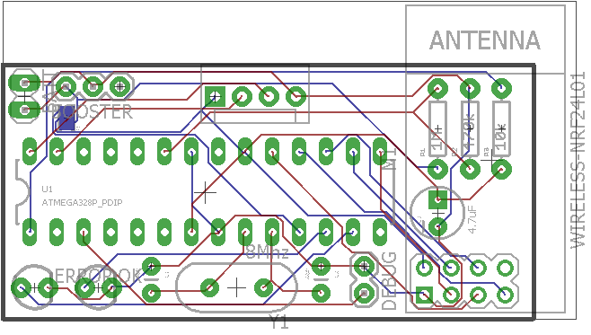
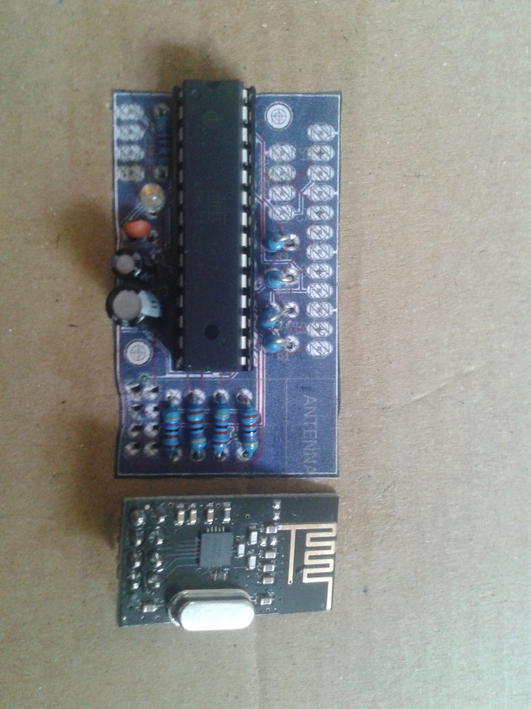
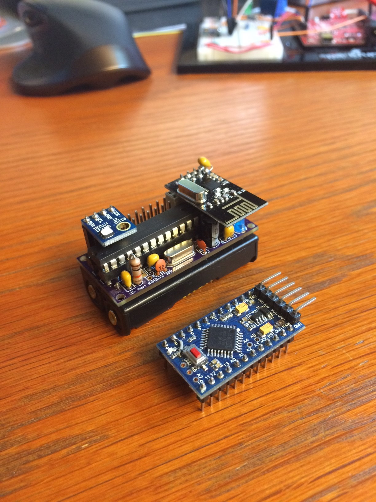
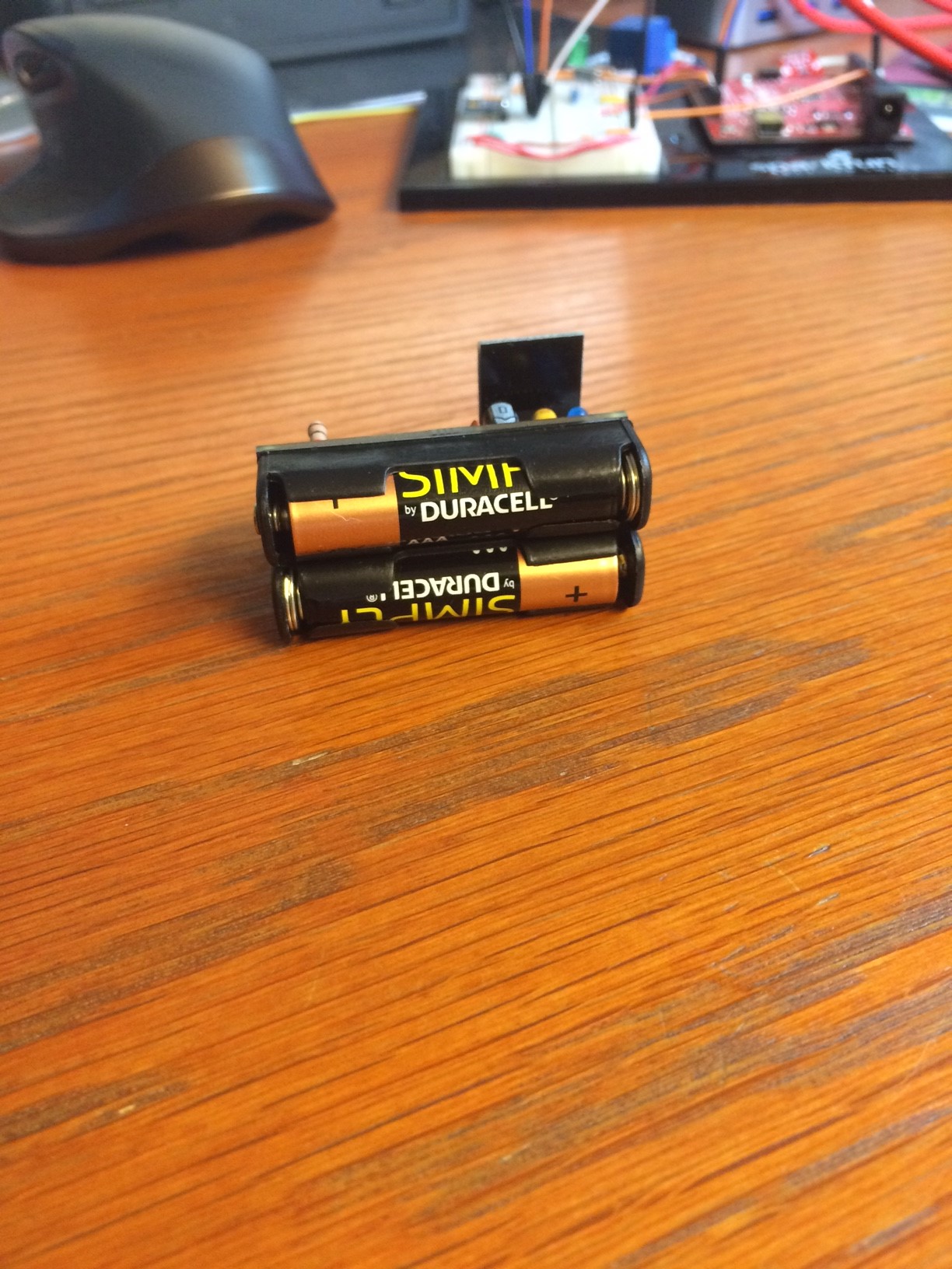
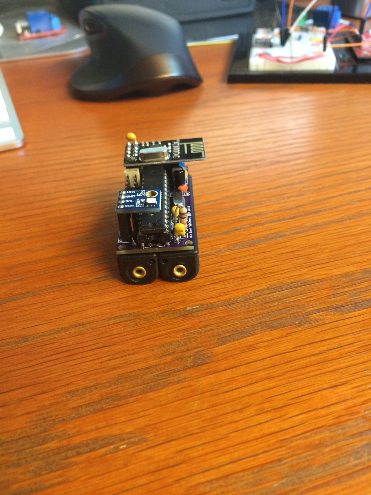
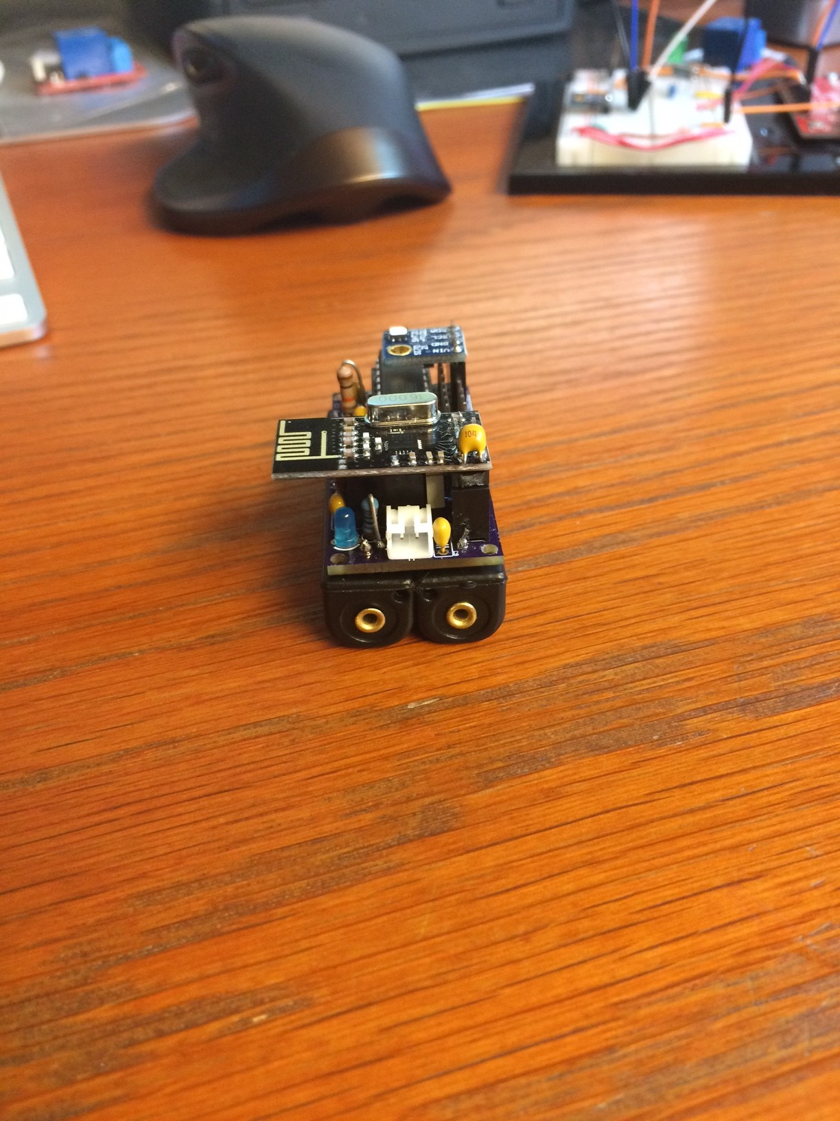
My own board (50mm x 30mm)


  • Hardware Contributor

    Hi all,

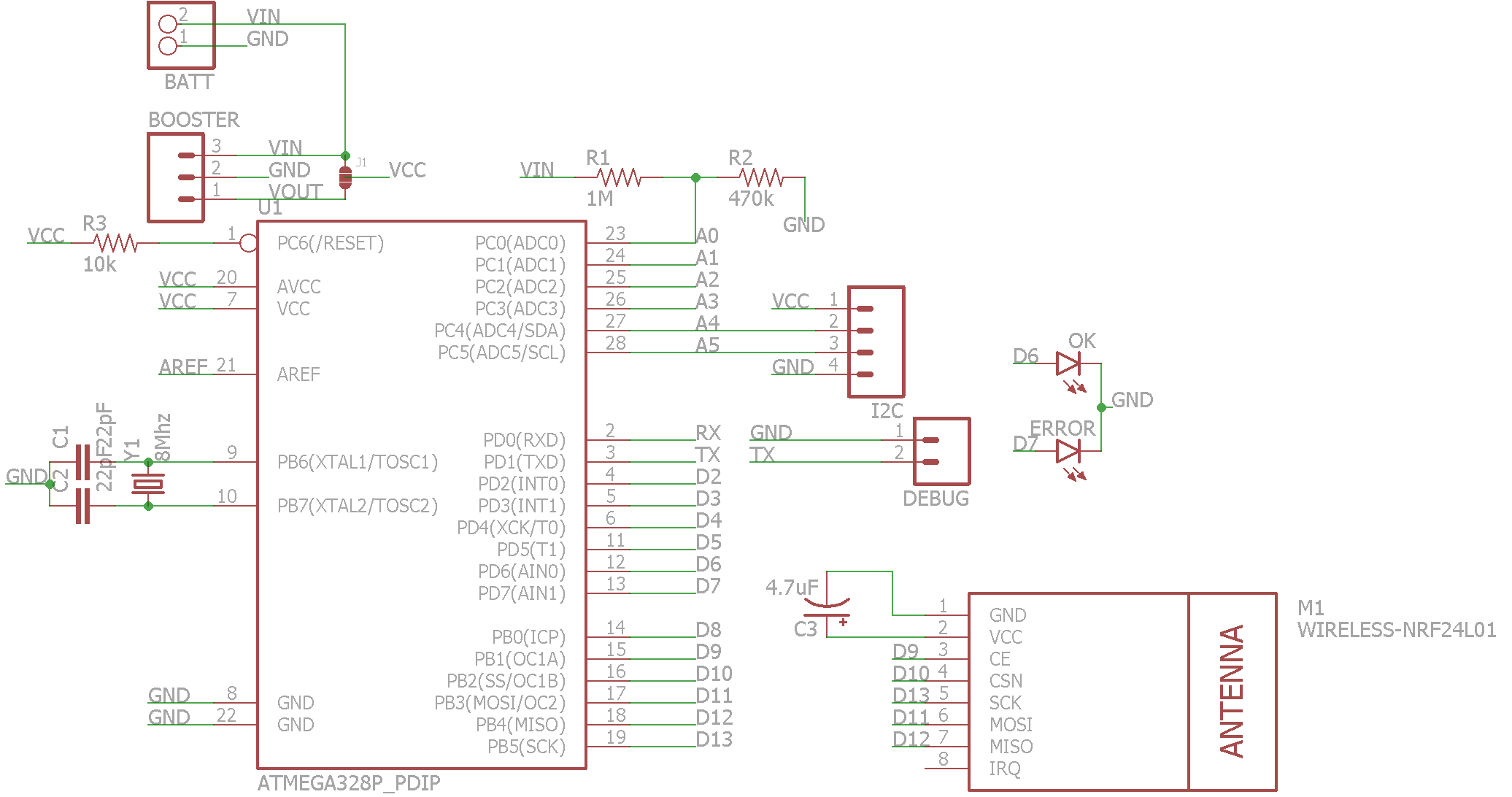
    i was never happy with the arduino pro mini and i dont like smd (too small for me). I was inspired by another design and so i decided to create my own board with "normal" components. i am not sure if everything is right, because this is my first selfmade pcb-design an my first project with eagle. So, i hope you can take a look at it and tell me, if something is wrong or what i can improve.

    This is the design:
    schema.png

    And this is the board.
    board.png

    Some background-info: I want to design an own board for every type of sensor i need. In detail:

    • 4x DS18B20 - powered with 3.3v-boost converter( seperate pcb)
    • I2C connector for LCD or Temp-Sensor (HTU21D)
    • Analog-Inputs for Moisture-Sensors
    • PIR-Board

    Here is only I2C-board. The other boards are nearly "identical" except pinouts...

    Every board has the same basic-features:

    • 2 LEDS (OK & Error)
    • Debug-Port (TX & GND)
    • Pinouts at same pcb-side (top)
      -Voltage Monitor included with solder jumper to chose input voltage. Reason: If the board is powered vi 3.3v booster, i need to monitor the raw-battery-voltage.

    The board is designed with eagle and seeedstudio design-rule. So i will order them when i have finished the design....

    What do you think about this?

    Greetings

    Andreas


  • Hi, it's great board, this is what i'm looking for!
    The only thing is that you can add Ultra-small DC-DC 0.8-3.3V to DC 3.3V Step UP Boost not as separate module, but on the main board, for example:
    http://www.aliexpress.com/item/Ultra-small-DC-DC-0-8-3-3V-to-DC-3-3V-Step-UP-Boost-PFM/32253709053.html

    What do You think?
    Best regards


  • Hardware Contributor

    Hi,

    i thougt a long time about placing such a booster on the pcb. Its quite difficult to find a good(!) booster. Lots of the cheaper booster draw a lot of current (quiescent current) - like the one behind your link. I tested only 2 until today.

    This one: http://www.exp-tech.de/pololu-3-3v-step-up-spannungsregler-u1v10f3?gclid=CPmll6rH0ccCFRI6Gwod884Lxg
    and this one: http://www.exp-tech.de/sparkfun-ncp1402-3-3v-step-up-breakout-prt-10967?gclid=CPCv55_H0ccCFUu6GwodKDUHwA

    Current consumption differs approx 30uA between those 2 (red 70uA, green 100uA in sleepmode with sensors etc)...
    Did you check current-consumption of your booster?

    Actually i am changing the board size to 50mmx24mm - its a lot cheaper to order from fusionpcb (seeedstudio)...
    Thats a lot.
    Greetings

    [β–²QUICK EDIT]
    Something like this? Booster soldered vertical....In this way you must select with the solder jumper how to power the board (battery direct or via booster)...schema.png board.png


  • Hardware Contributor

    Looks nice. Some initial thoughts:

    1. Shouldn't IRQ in the radio be attached to the arduino?
    2. Is the capacitor under the radio on the opposite side of the board (clearance issues)?
    3. You might want to add mounting holes. They need more clearance than you might expect for screw sizes. See this link for details
    4. Is the capacitor C3 connected to the radios VCC pin? It looks like it might be connected to VCC but not to the actual pin on the radio. Bypass caps should be as wired as close to the component pins as possible.

    Hope that helps. I'm working on my first board right now as well so keep in mind that those comments are from another amateur and could be totally wrong πŸ˜ƒ


  • Yes, great. Thanks. I'm also newbie and I don't have experience yet with booster.
    The next ting is the case for this sensor, maybe with battery holder ...


  • Hardware Contributor

    Hi,

    thanks for your feedback guys :). Looks like i am on the right way. Only some things before breakfast (hope my wife doesnt see me at the notebook instead of making breakfast) πŸ˜‰ I will answer the other tipps and questions later from work πŸ˜‰

    • IRQ-PIN: Is not needed for batterypowered devices, because the radio cannot wake up the IC.
    • Cap C3: Plan was to solder it horicontal - i just didnt find the part in eagle. Both, atmega and nrf, will be mounted into sockets. So there should be enough space under the NRF module for a 4mm Cap. But maybe your are right and its easier to solder the cap directly onto every NRF-module...
    • Case: I have no 3D-Printer, only CNC. So i have an Idea for a case - incl. Batteryholder. But i will show this later. Its only in my mind, not in my CAD-Programm actually πŸ˜‰
    • Mounting holes: is a "ToDo" πŸ˜‰

    Greetings
    Andreas


  • @ahhk where did you downloaded that nrf eagle part/library from?


  • Hardware Contributor


  • Hardware Contributor

    This post is deleted!

  • Hardware Contributor

    My development continued. I have now a "Baseboard" and a "Topboard". First i created different topboards for different sensors. But at last i made a "general" Topboard. Here i can connect all the sensors i need. It has

    • 5x Digital-Connectors prepared for DS18B20 (GND, SIG & VCC), but can be used for other digital in-outputs. Just do not solder the resistor
    • 3x Analog-Connectors for connecting analog-devices. (can also be used as digital pins)
    • Place for an Step-Up-Module. If the sensor is powered directly with 2xAA-battery just put a jumper to connect BAT & VCC.
    • I2C -Connector with VCC and GND
    • Batterymonitor-Pin for Baseboard (A0)

    This is the Topboard:
    topboard.png!
    Top-Schema.png

    The Baseboard has:

    • NO smd-parts
    • Debug-port (TX &GND)
    • Mysensor-Voltage-Monitor (2 resistors) onboard. Solder it or not if not needed
    • 2x LEDs (Red & green) = Error & OK
    • 4x 3.2mm holes for mounting

    This is the Baseboard:
    baseboard.png !
    Base-Schema.png

    Both boards are 25x50mm...
    Now i have to find out how to print them in 1:1 (original size) for testing.


  • Hardware Contributor

    Here is some feedback from designing my boards:

    You need 100nF capacitors between AVCC and GND and between VCC and GND.Put them as close to the actual pins as possible. And you need to pull ARef to ground via a capacitor (can be 100nF as well). All this improves stability of powersupply to the processor (and less restarts)

    To test the battery voltage (if powered directly from 2 AA or 2AAA batteries, there is no need to use the 2 resistors, there is a routine to test the battery voltage based on internal reference (so no analog input pin needed).

    You could use a single LED to show what is going on: slow blink means all OK, fast repeated blink means error. This saves a resistor/led/output pin.

    The 100uF capacitor is a 8x12mm type and fits just under the NRF24. You can go for a 10uF which are normally a bit smaller and have no clearance issues (only 8mm high, so well below the 12mm space available).

    How do you plan to program the board ? It could be nice to add the FTDI comptible header on the top board, or you can also add it on the main board.

    Here is a link to my design:
    https://oshpark.com/shared_projects/qnkNIMZx

    Schematic is in the next post.

    Like yourself I only use through-hole components (except on the extention board). I can add extentions on top or on the bottom of my board.

    Another tip I got from other people: powerlines need wider traces,

    I have been thinking about replacing one of the headers I added (for the top boards) with a header according to the MYSX 1.5 specification. So far I have not finished this, but it is on the todo list.

    A 50mm by 24mm board allows powering by two AAA batteries onboard, so my next design provides for this as well (it's a work in progress).

    But after three designs I now work in reverse: first look for a nice suitable case, then design the board to fit with ITEAD/DirtyPCB spec (50mm x 24mm to have 2 boards out of a 50x50mm run).

    Since I test on prototype boards and transfer sketches to "final" boards later, I think I can integrate the FTDI header into JP1. I also plan to re-arrange the I2C pins so that I can plug in boards from Sparkfun, without any adapter. They (Sparkfun) use a fixed sequence for all their I2C boards:
    GND - VCC - SDA - SCL
    Some boards are VCC - GND - SCL - SDA. Not sure which is more popular, as I have seen both on Aliexpress and eBay.


  • Hardware Contributor

    Here is the schematic of my current v1-1 board (based on the work of many other people):

    upload-f9f6f028-3f77-4e14-b667-97b6c618d3ba

    The new (battery included) board is still to "fluid" to show. When fixed I will probably also share this on OSHPark.


  • Hardware Contributor

    Hi Gert,

    thx for your feedback. Lets make a small structure to discuss the things:

    Battery-monitoring
    I plan to you use the AREF as 3.3v Reference powered by the step-up-module. I think most of my sensors will have a step up. So this should be quite easy and accurate. In this case i solder a wire instead of R1 and "unsolder" R2....
    OR (if i really want) i can use the voltage divider on A0 instead (like mysensors.org says). I think with this schematics i have both possibilities... How does it work without resistors and internal vref (1.1v)? I only saw the version with 2 resistors on the mysensors page.
    By the way: I tested 3 step-up-modules:

    Pololu with NCP1402
    Sparkfun with NCP1402
    "China-Module"

    The China-Module is crap (+-240uA).
    Pololu draws +-100uA in sleep mode
    The Sparkfunboard only draws +-30uA in Sleep mode. I will go for that.

    Capacitors:
    There is a capacitor between VCC and GND. The capa between AVCC and GND is missing, you're right. Thx.
    I want to use AREF, so i cannot pull it to ground. Or what did you mean? Or am i missunderstanding something? I thougt AVCC is the supply voltage for the "REF"-function. And AREF is the reference-voltage....

    Programming
    In an updated version from last night, i moved the debugport to the topboard. I can upload new sketches via RX/TX...
    Do you know if it is possible to use the ISP when the NRF24l01+ is still connected to these pins?

    LED
    I dont want to have a regular LED-blink (power consumption). It shall only blink when working(transmitting).
    Green => All OK: Measures are ok, packet was sent
    RED => ERROR: Measurement fails or packet could not be sent...
    A DUOled would save some space, but no pins.

    Sensors
    I think i will have a max of 5 Sensors connected on one board , so there is no need to save pins whereever i can.
    The I2C port is like the sparkfun "standard" πŸ˜‰ I have a lot of HTU21D-BOBs laying around. They work like a charm

    After i gave my child something to eat, i update and upload the schematics...give me some time πŸ˜‰


  • Hardware Contributor

    Here the schematics with boards..
    Baseboard
    base.png
    basebrd.png

    Topboard
    top.png
    topbrd.png


  • Hardware Contributor

    Battery-monitoring
    The capacitor between AREF and ground (C3 in my schematic) is not to pull that pin to ground, but to stabilise this reference. Not strickly needed I think, but I prefer it since my sensors will live in a "noisy" environment.

    The code to check the level of VCC using the internal 1.1V reference is found here:
    http://provideyourown.com/2012/secret-arduino-voltmeter-measure-battery-voltage/

    The error of 10% is something I can live with, since I need to be able to measure the supply-voltage and monitor it. It does not need to be super exact, since I plan to replace the batteries when I see levels around 2.2V. I'm mostly interested in the trend graph.

    When using a DC stepup converter, you will of course need to use a pin to measure the original battery level, because the step up will make VCC always 3V3. I like your idea of dual use, so I will implement the pins to hold a voltage divider anyway. It is indeed a good use of PCB space.

    I also ordered some step up converters (from Aliexpress) and I will measure them once I get them. Not all China stepups are crap it seems (as far as I read on various websites).

    LED
    As for the LEDs, I have only 1 LED on my boards. The LED blinks very shortly (5ms) every minute to show that a message is sent. It flashes three times if there is an error. So no need to have two leds. It is also the same LED that is flashed by the bootrom (I'm compiled nmy own version of Optiboot to used pin 14 of the atmega328. On a atmega1284p I use pin 1. This is personal preference.

    I checked your schematic. You will need to change the value of C1 (it is now 22pF, will need to be 100nF).

    I will need to read the datasheet of the atmega328 again to understand the exact use of AREF. I'm not sure that pulling this to VCC is a good idea.

    It seems you have removed the crystal and capacitors and plan to use the internal oscillator, I did this as well. Works most of the time, but uploading of sketches can give transmission errors of you go above 57K6 baud. Better to transmit at 36Kbit then (needs a change in the BOARDS.TXT file of Arduino IDE). Slower, but not a problem if you do not plan to change the sketch every 5 minutes.

    Here is a preview of my new board:
    upload-ef70e5f9-9073-4b47-a074-4a48779f1004

    It will be able to work both as a repeater (NRF24 with antenna) as well as a normal sensor board (small NRF24). The voltage divider on A0 is not yet implemented here. Still some empty spaces πŸ™‚


  • Hardware Contributor

    Hi,

    thx for the feedback. Capa is changed to 100nF. It also works on my breadboard with 22pF πŸ˜‰

    Battery-Monitoring
    The link to measure the vcc internally is great! Wow! Does this solution block any pins?
    But i stay with my double-solution - it is not too big on the pcb.

    Crystal
    Yes, i progged the fuses to run at 8Mhz-internal. Runs great and saves parts on the pcb and makes it cheaper πŸ˜‰

    i am not sure, i understand your board. What are all the connectors for? Where is the ATMEGA? Size?

    Maybe we can join our board-ideas and design one-board together? πŸ˜‰

    I am missing mounting holes on your pcb...

    Case
    I willl make my own case - a wooden case milled with my CNC...
    8mm Multiplex (or plywood)...looks quite good i think πŸ˜‰


  • Hardware Contributor

    Different version with mounting holes:
    upload-2854219b-739f-4d11-984c-f73b8519be82

    Schematic:
    upload-1e4c0b8f-b650-4ffb-a991-b9965b6add48

    Topsilk+documentationlayer:
    upload-4281ea10-4bdf-4285-9198-cc8aa3e5e7e1

    Bottomsilk +documentationlayer:
    upload-29293821-220a-494c-b3a3-74f9c923e2ac

    As I said: a work in progress. Nothing fixed yet.


  • Hardware Contributor

    Incredible many pinouts and holes! Wow! Are you sure you need them all? Looks much more complicated then my design. But looks cool, too πŸ™‚

    This is my Case-Prototype - very flexible and easy to manufacture:

    CaseOne-Top.PNG CaseOne.PNG

    The top is adapted to every node-type. E.g. in the picture is the top for the humidity and temperature sensor. Then i plan to create a top for a PIR-Sensor, Acoustic-Sensor and a case for external Sensors and Powersupply, too.
    Maybe i engrave the type of the sensor into the top for a cool looking.

    Then i glue it together or use small magnets. Case is still in "alpha"-status - work in progress. If i need it higher, i just add a second, third (...) bottom part. Every part is made of 8mm wood. If i want another design, i can make a "cover" for the top or use other materials for this (Aluminium, POM,different wood, acryl...) Connections from the side are easy to realise, too. Just drill a hole after building or mill it before putting it together.
    If i could make a 3D-Modell from my PCB (and know how to do this with eagle), i could make a really nice picture with case, pcb and batteries...

    Size is approx 60x40mm.

    Greetings

    Andreas


  • Hero Member

    @ahhk said:

    This is my Case-Prototype - very flexible and easy to manufacture:

    Why do you say it's "easy" to manufacture?


  • Hardware Contributor

    @Andreas: nice woodcase. Do you have access to a CNC machine at home or at work ?

    My design is based on the idea that I want to have a maximum of options with the same PCB. Last night I printed some boardoutlines on paper and then placed the actual components on top. I find limitations in space this way. My idea of 1 long connector has a disadvantage: the small radio covers 4 pins, so that a top board would not be able to plug into these. I went back to a seperate header for the small radio and for the top board.
    Still thinking about powering options. VRAW (anything external), VCC (regulated to maximum 5V, e.g. from a USB port), 3V3 (regulated via bottom- or top-daughter boards), VBAT (from onboard AAA batteries). The problem is finding an elegant and easy way to choose. Solderpads are compact, but permanent. Jumpers are easy but big. Small toggle- or slide-switches are expensive.

    The fruit of last night's meditations:
    upload-28d0b2a4-7a0b-42a5-8be4-621438373d1d

    I have still not decided if I should use the pintout of the SI7021 breakout modules (VCC-GND-SCL-SDA) or the HTU21D (VCC-GND-SDA-SCL). Most breakouts seems to use 3V3, so I may need to plan for that.


  • Hardware Contributor

    hi.
    nice boards guys!
    yep, so lot meditation for tiny things πŸ˜† I am still asking myself on some points..

    in my case I choosed solderpads. not difficult to change and it is small. but not as easy to use as jumpers. I think jumpers are useful for proto stage but then in real you won't need it and it will take place.

    I was thinking about having pinout for breakout too. but what if sellers change or stop boards. I don't think so, but it could happen...and it increase overall size too.
    but I understand your vision of your board (mine is full smd). I like your ideas too!

    See you soon and good luck for meditation πŸ˜„


  • Hardware Contributor

    @NeverDie said:

    @ahhk said:

    This is my Case-Prototype - very flexible and easy to manufacture:

    Why do you say it's "easy" to manufacture?

    I put a wooden 8mm-plate on my cnc and mill the parts πŸ˜„ Very cheap and fast made....

    @GERT: I have a cnc at home. i built it several years ago πŸ˜‰ Take a look if u want: http://www.rc-network.de/forum/showthread.php/304809-CNC-FRΓ„SMASCHINE-OPEN-SOURCE-PROJEKT/page11

    Power
    I have only 2 possible variants in mind:

    • Battery with or without step up (plugin boost converter)
    • USB-Powered

    For the last one i wanted to use these pcbs - glued into the case or plugged instead of the step-up module:
    http://www.ebay.de/itm/301652467812?_trksid=p2060353.m2749.l2649&ssPageName=STRK%3AMEBIDX%3AIT

    Or i install a small connector into the case and solder 2 wires to the board. Something like this http://www.ebay.de/itm/2-Pair-DC-Power-Female-Male-Connector-Cable-Pigtail-Plug-Wire-CCTV-camera-White-/252099946337?hash=item3ab253e761

    Everything should stay "easy&simple" and i think, once installed, the sensor will "hang around" for a year or longer....

    Sensors
    I checked 3 properties to find the correct sensor:

    • minimum allowed voltage
    • time for a measurement
    • price

    So, the htu21d was the winner for me - works great and fast after a little optimization of the arduino-library for this (replaced delay with gw.sleep)...


  • Hardware Contributor

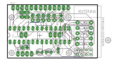
    Next variant. Less flexible, but flexible enough. Boardsize now 50x30mm
    It's only one pcb now and you can connect

    • 5x sensors (digital or analog)
    • 1x I2C and 3x sensors (digital or analog)

    Step-up can be soldered to the bottom.

    What do you think?
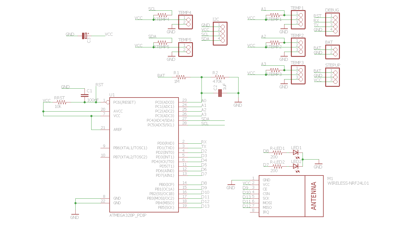
    base2sch.png base2.png


  • Hardware Contributor

    hi Andreas,

    What is the intention of TEMP4 and TEMP5 connectors ? I see that you pull up SCL and SDA, but all these connectors can do now is give VCC and GND on pin 1.

    For TEMP1->3, it depends on how the sensor actually works. With Light Dependant resistor there is no issue. For other sensors (TMP36), a resistor pulling up to VCC would be a problem. A switch would be OK between pin 1 and 3 (GND) of those connectors. What is the usecase ?

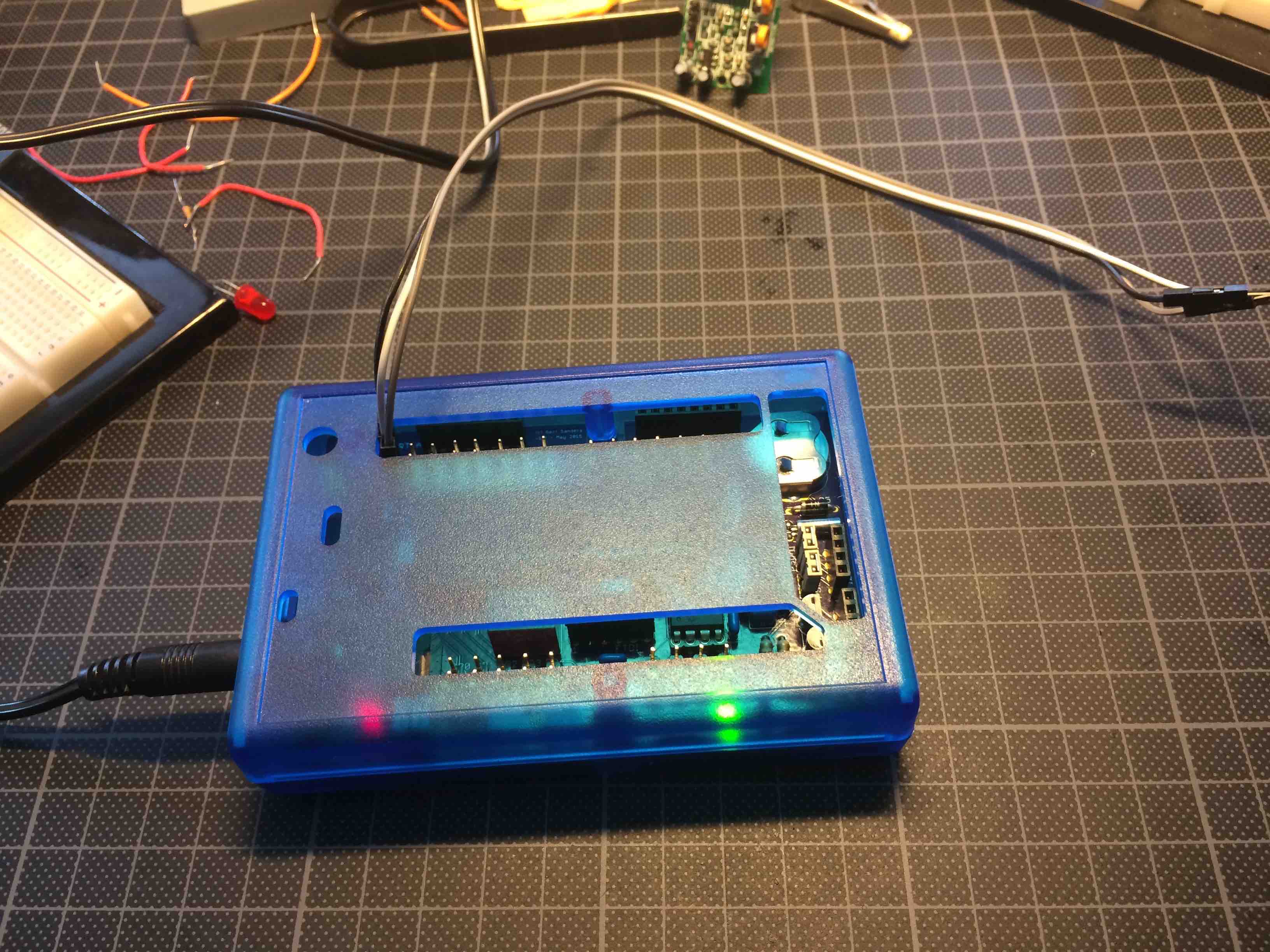
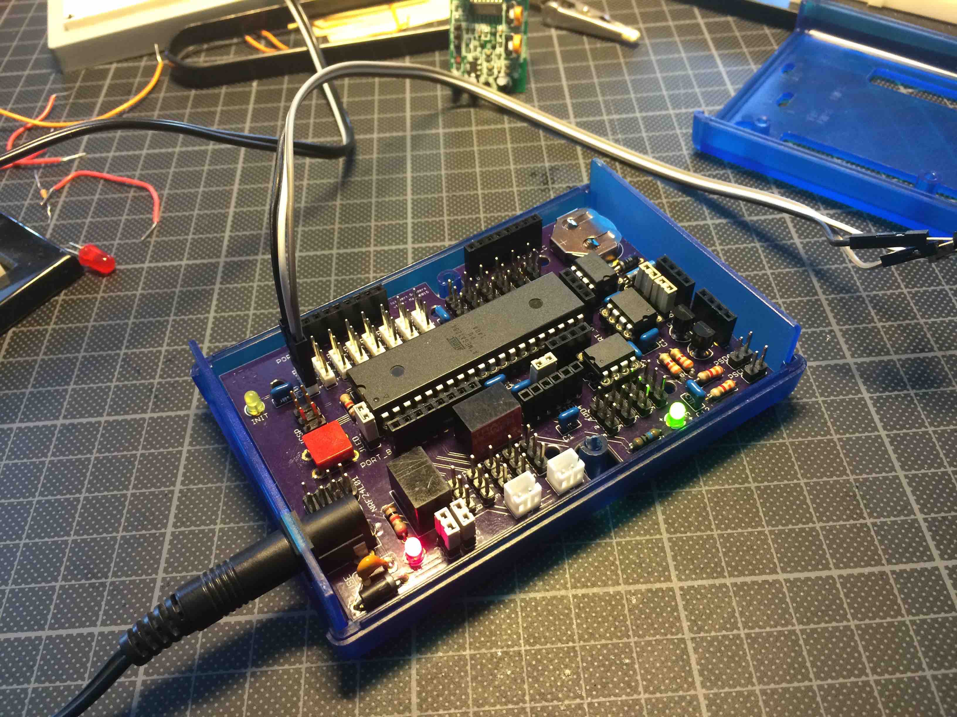
    I have a atmega1284 based design, which is not yet shared on OSHPark. The version I made has the NRF24 connector in the wrong direction (but this is still useful). However, I can not close the case with the NRF24 in place. It was made for a Hammond 1593N case (the transparent blue type, very cool):
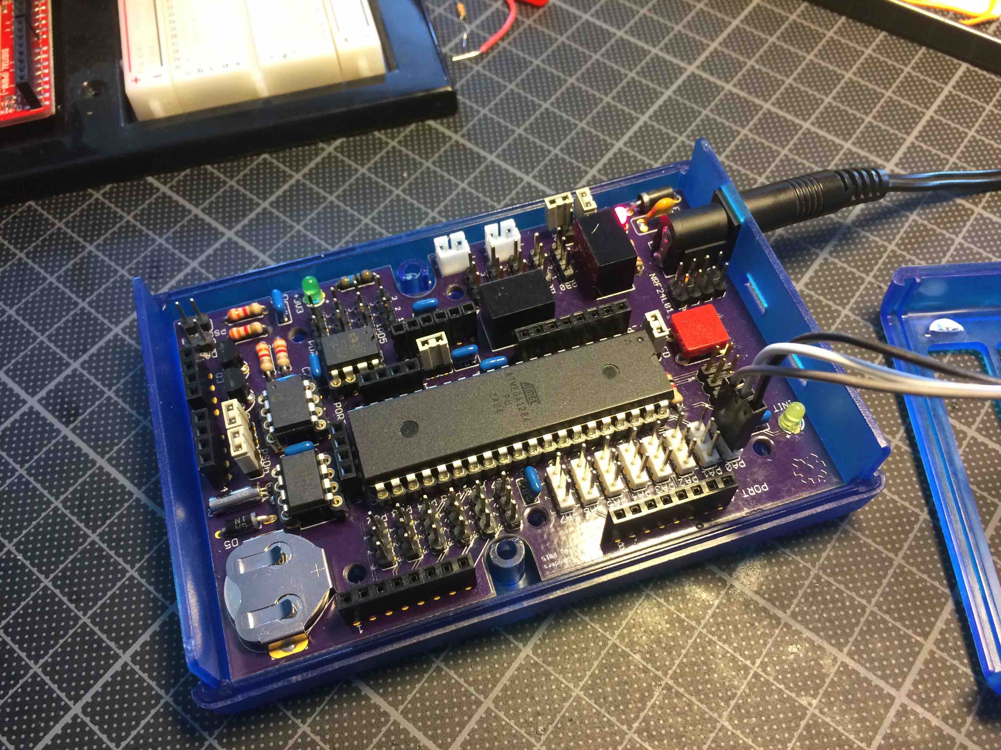
    IMG_6861.jpg
    IMG_6860.jpg
    IMG_6859.jpg
    I used the case for the Arduino Due (bought this from Mouser).
    I now corrected the orientation of the NRF24 connector but this not put this on OSHPark, because I can live with the mistake I made. Many ports on this one. But only works on 6-24V input. The power converters are from TRACO (1 for 5V, 1 for 3V3). It has 64KB EEPROM and RTC. Level converters for 5v->3V3 on I2C (so 2 I2C ports actually) and most pins are brought out together with 5V and GND.
    The point here is that adding resistors to the three pin connectors is not really necessary. But it is nice to have signal-VCC-GND on three wires each time.
    I think I will order the 1593K case next (to see what can be done with that), nice little box.


  • Hardware Contributor

    @Andreas: Very impressive CNC machine !!!


  • Hardware Contributor

    Hi Gert,

    thx for the cnc-flowers πŸ˜„

    Sensors

    I thougt about the different nodes i will have later. The biggest node will have 5x DS18B20 - so i really dont need more than 5 "ports" to connect sensors. I changed them to the analog-pins of the arduino, because i can use them as digital and analog ports too...

    Temp4 and Temp5 can be used as I2C ("horizontal") OR as Temp4 and Temp5 for DS18B20 ("vertical"). See top left corner of the board. I think it is very flexbile to not solder the resistors (disconnect VCC) or to solder a wire instead of the resistor (vcc to pad). In this way i can connect PIRs, DS18B20, Analog-sensors and so on....i just solder the parts i need for the sensors...

    Only thing: I cannot use I2C AND Temp4 / Temp5 at the same time, because A4 and A5 are SCL and SDA too....
    I hope you understand what i mean and try to reach...

    Btw: Jumper-pins are not a must, if i want, i connect the sensors via wire to the pads, or solder them onto the pads directly....

    Greetings

    Andreas


  • Hardware Contributor

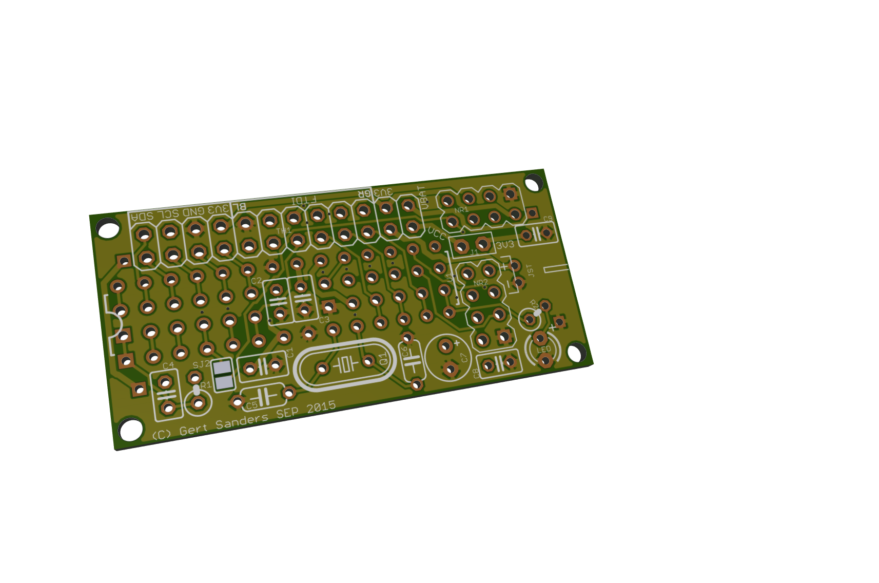
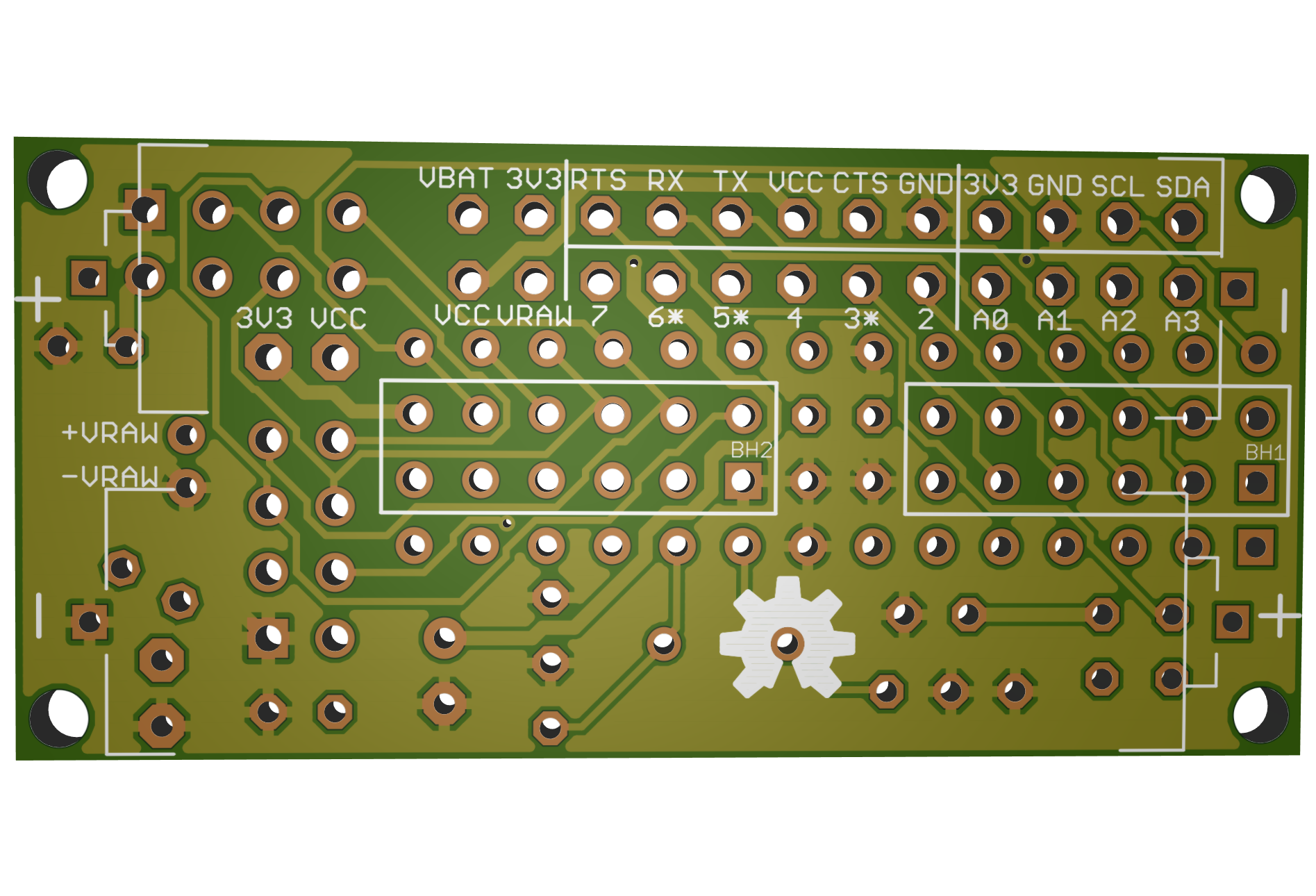
    A 3D view of my lastest board πŸ‘

    upload-075a0c14-d55f-4c52-946c-8962127de3fb
    upload-9c879fc0-e05c-4eb7-91f7-5a2d307244fb
    upload-c4bb585c-691d-4211-87d7-ac5b78906a26
    upload-6505f209-0883-45ac-999b-0ae1b85be314

    Tool used: http://mayhewlabs.com/3dpcb

    So cool to see a 3D render, very fluid when moving around πŸ™‚


  • Hardware Contributor

    Hi,

    3d-view is really nice. I dont know why, but my gerber files dont work. Board is BIIIIIIIGGG and without holes 😞

    I asked in the hardware-forum, if there are any errors in my design. (http://forum.mysensors.org/topic/2042/errors-in-pcb-design)

    I must finish this and order my boards now πŸ˜‰ Otherwise i will never find an end....


  • Hardware Contributor

    Getting close to final layout myself ....
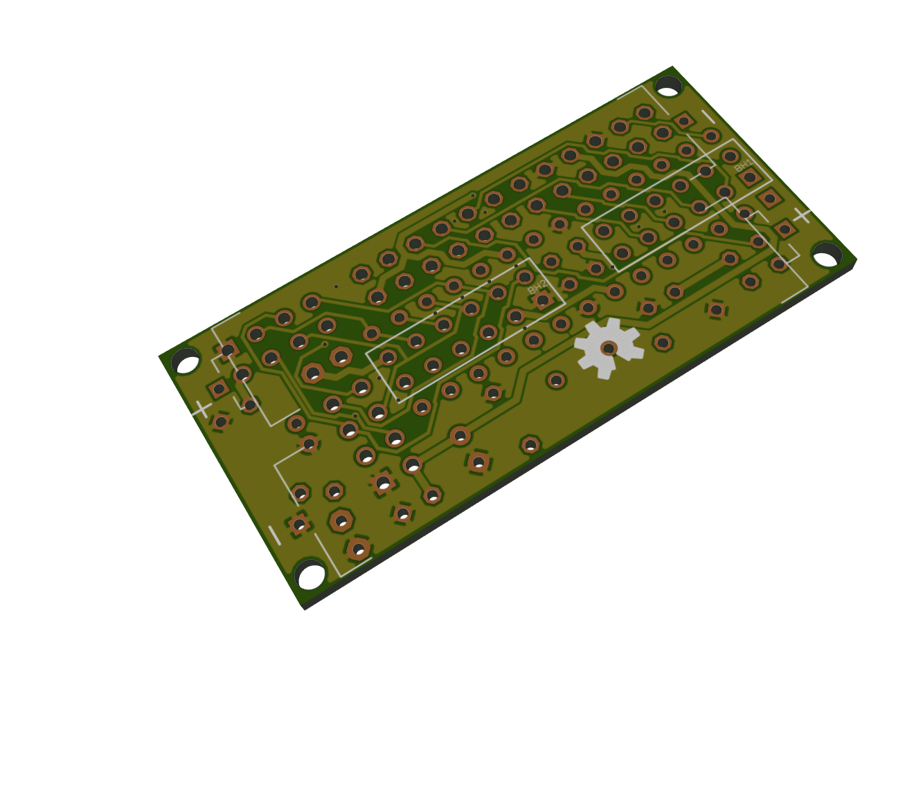
    Unknown.jpg
    Unknown-2.jpg


  • @ahhk said:

    Hi,

    i thougt a long time about placing such a booster on the pcb. Its quite difficult to find a good(!) booster. Lots of the cheaper booster draw a lot of current (quiescent current) - like the one behind your link. I tested only 2 until today.

    This one: http://www.exp-tech.de/pololu-3-3v-step-up-spannungsregler-u1v10f3?gclid=CPmll6rH0ccCFRI6Gwod884Lxg
    and this one: http://www.exp-tech.de/sparkfun-ncp1402-3-3v-step-up-breakout-prt-10967?gclid=CPCv55_H0ccCFUu6GwodKDUHwA

    Current consumption differs approx 30uA between those 2 (red 70uA, green 100uA in sleepmode with sensors etc)...
    Did you check current-consumption of your booster?

    Actually i am changing the board size to 50mmx24mm - its a lot cheaper to order from fusionpcb (seeedstudio)...
    Thats a lot.
    Greetings

    [β–²QUICK EDIT]
    Something like this? Booster soldered vertical....In this way you must select with the solder jumper how to power the board (battery direct or via booster)...schema.png board.png
    Hi ahhk,
    Can You share brd files for this version? Thanks.
    Maciej


  • Hardware Contributor

    Hi,

    sure i will share the brd-file and schemativ. No problem. But let me first build one working sensor. I think i will order the pcbs this weekend, because this looks good too =>
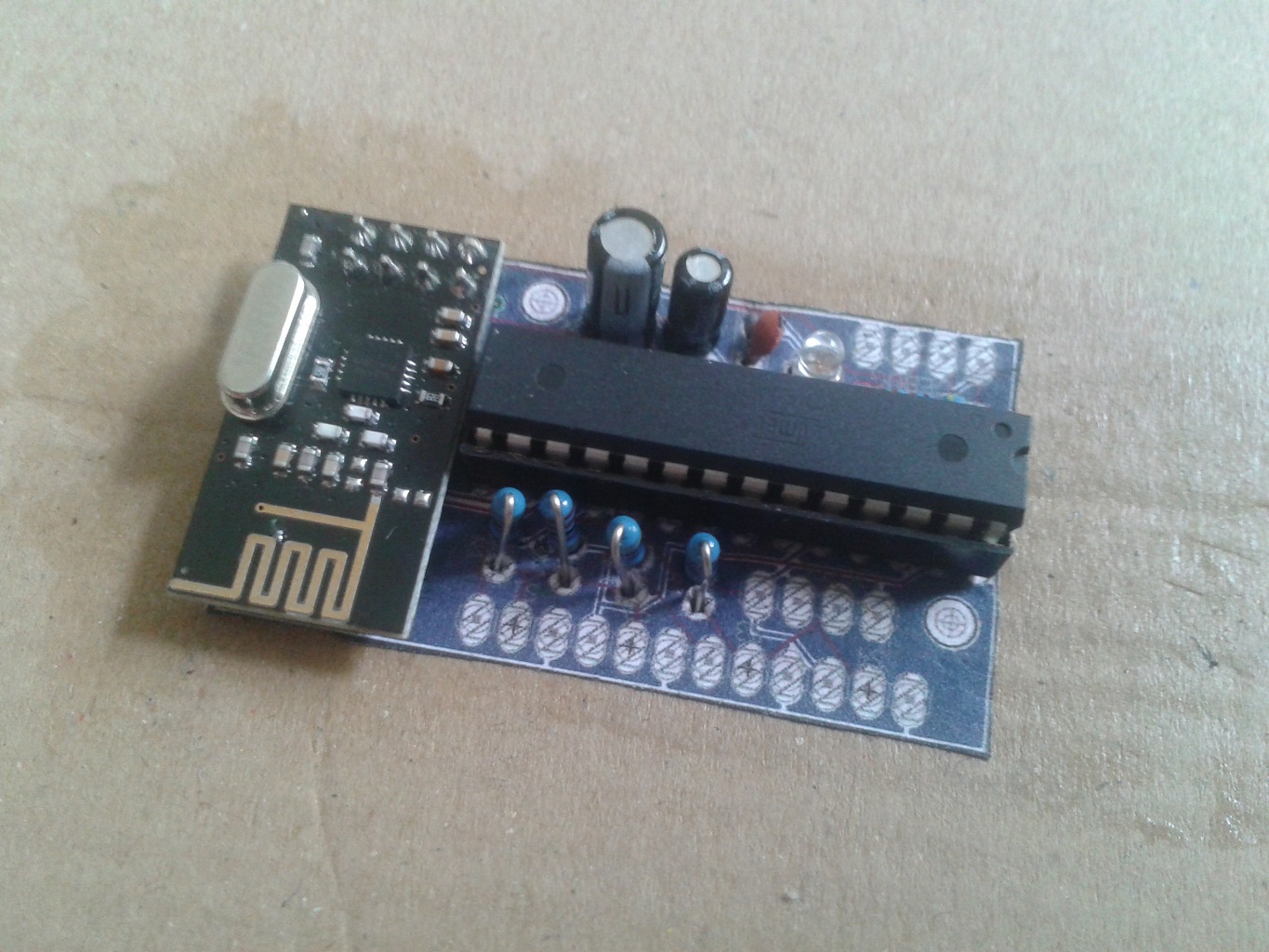
    IMG_20150925_130732.jpg IMG_20150925_130712.jpg


  • Hardware Contributor

    Done, this will be sent to the PCB makers:

    Top:
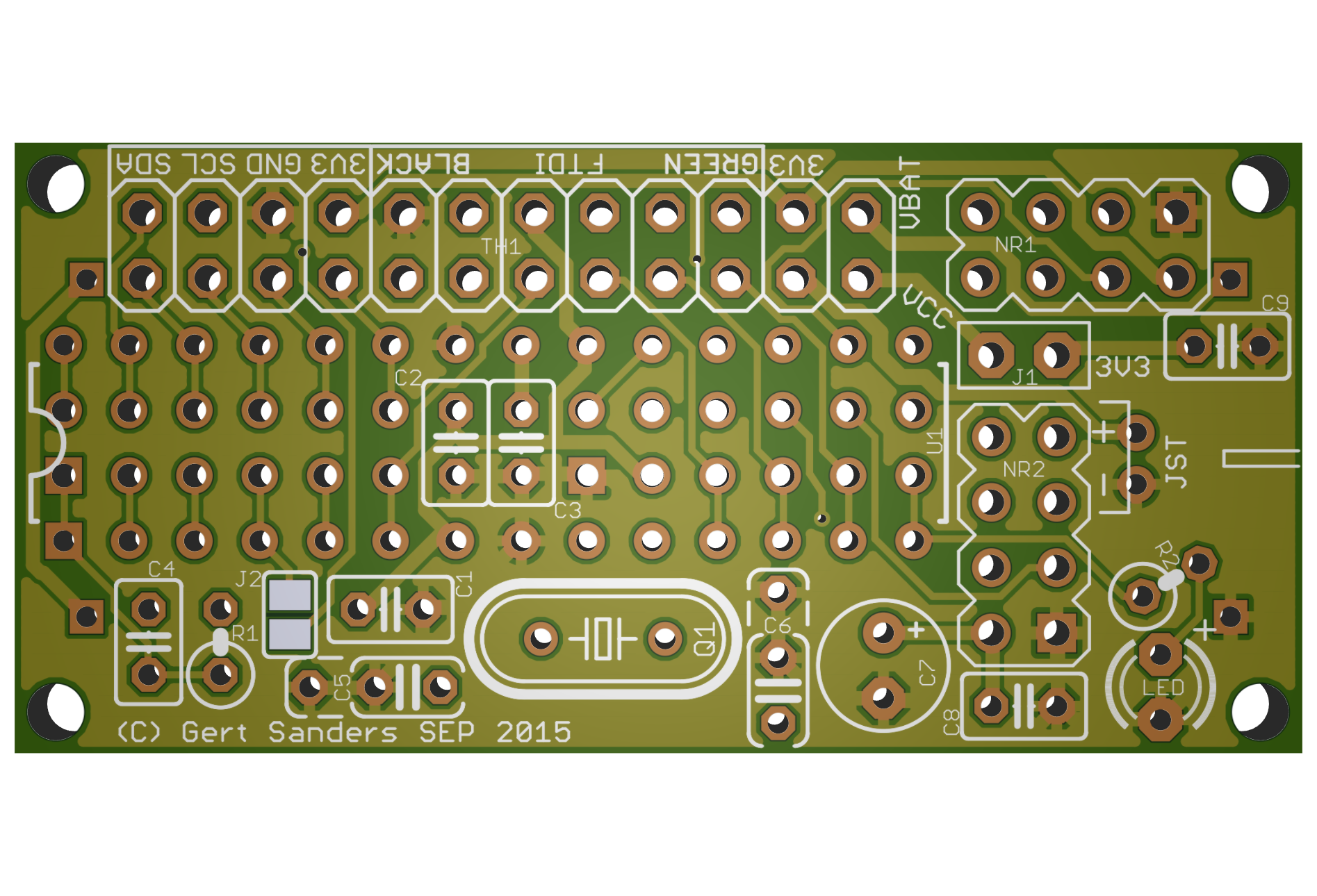
    top.png
    Bottom:
    bottom.png


  • Hardware Contributor

    each boards are nice, good work πŸ˜‰


  • Hardware Contributor

    PCBs are ordered (shenzen2u)....i am very curious about it πŸ™‚


  • Hardware Contributor

    Update: PCBs are shipped via express... πŸ‘―


  • Hardware Contributor

    Update: this arrived in my mail today:
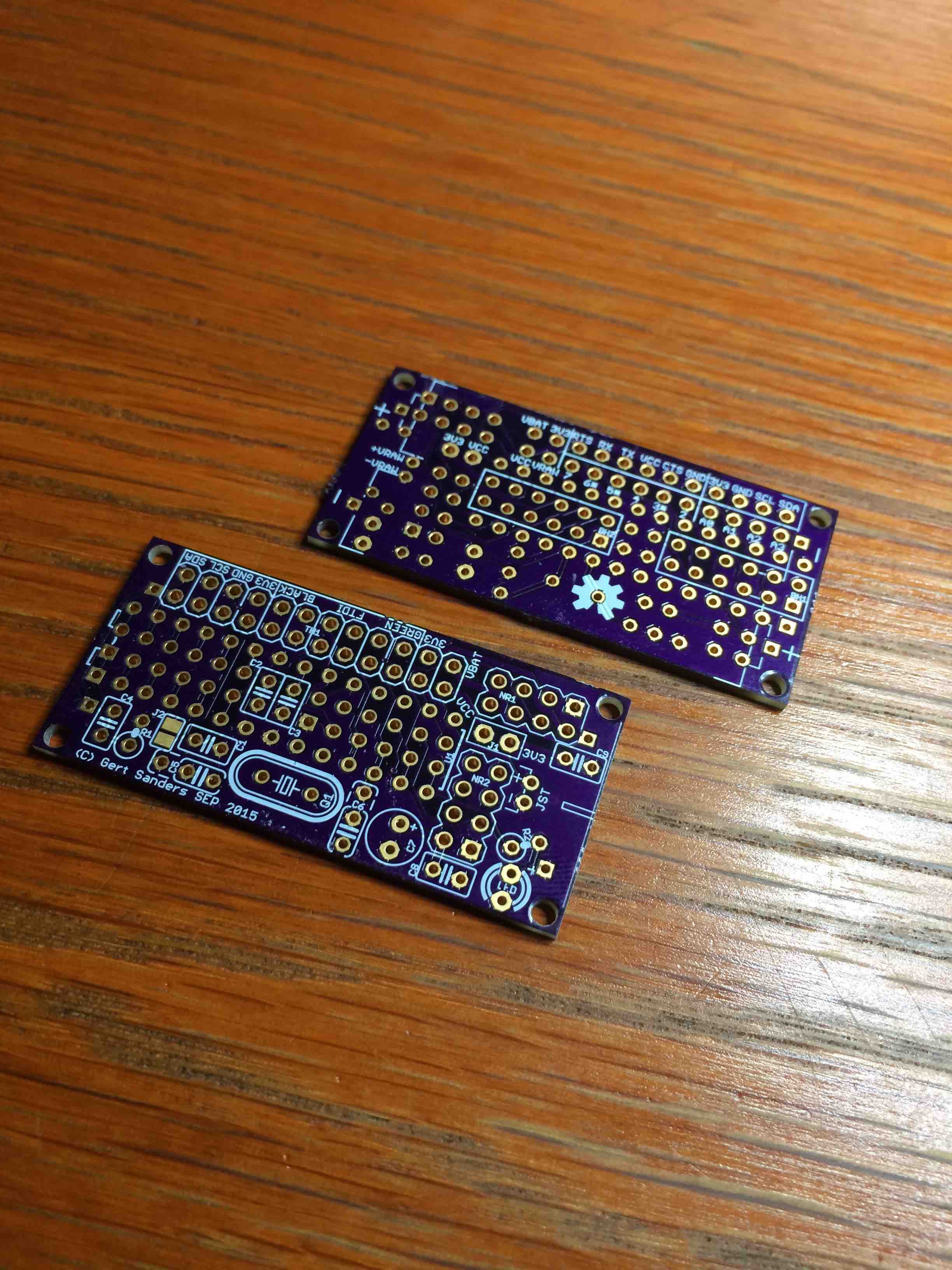
    IMG_7353.jpg
    I also ordered a set from DirtyPcbs, which were ready lastweek monday, but are still on their way to me.
    Assembly starts tomorrow πŸ™‚


  • Hardware Contributor

    ok, great πŸ™‚ Lets how they look ready....


  • Hardware Contributor

    Here is version 2 of my sensor:
    IMG_7363.JPG
    IMG_7368.JPG IMG_7367.JPG IMG_7366.JPG IMG_7364.JPG


  • Hardware Contributor

    This post is deleted!

  • Hardware Contributor

    Maybe its better to open a new thread for this question? πŸ˜‰


  • Hardware Contributor

    Just realised this. Indeed, I will start a new topic.


  • Hardware Contributor

    Second variant with the same board. This one actually sends it's messages better (no more st:fail's):

    IMG_7380.jpg IMG_7383.jpg

    And it's nice and compact. Now I need to find a nice ventilated little box to protect them from dust.

    This board is now tested and shared on OSHPark: https://oshpark.com/shared_projects/unP8BmuI

    Component values are mentioned in the brd file. I will add a BOM in Excel format later.


  • Really great job!!!


  • @GertSanders said:

    Now I need to find a nice ventilated little box to protect them from dust.

    This might work - it's well ventilated; width & depth OK, but don't know about height.

    http://www.ebay.co.uk/itm/291147751395?_trksid=p2060353.m2749.l2649&ssPageName=STRK%3AMEBIDX%3AIT


  • Hardware Contributor

    My dirty dirty boards have arrived today πŸ™‚
    IMG_7493.jpg
    I actually received 12 boards, so I can make 24 sensors, great succes πŸ‘ !!!


  • @GertSanders
    Please post the BOM.


  • Hardware Contributor


  • Hardware Contributor

    Preview of my latest board, waiting for prototypes to test this ....
    topview.png
    bottomview.png
    This is a 50x50mm board with multiple powering options (AA or AAA batteries, direct 3.3 or 5V DC, 4.5-20V DC in, 220V AC) and can fit a GSM module at the same time as the NRF24 radio. Allows 2 variants of I2C connection (SDA and SCL on IO header can be swapped via soldering pads). Room for signing chip and some I2C based EEPROM or FRAM memory. Several connectors for digital pins with power.
    Fits into this box:
    http://www.aliexpress.com/item/Free-shipping-2-pcs-lot-60-58-28mm-plastic-housing-DIY-project-box-ABS-junction-box/2039860908.html


  • @GertSanders said:

    @Didi Here is the BOM and EAGLE files.

    Thank you


  • @GertSanders Hi Gert, on the small board, did you soldered C2 and C3 on the bottom or on top just under/in the IC socket?


  • Hardware Contributor

    @pjeterinfo On one of the sensors I soldered it on the bottom between the two connectors on the bottom.

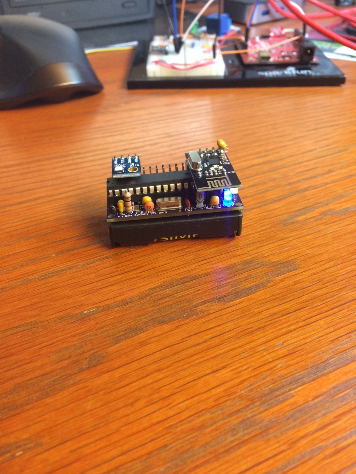
    For the sensors where I add the batteryholder on the bottom, I do indeed solder these capacitors on topside between the legs of the chip. Later this evening I will make a photo of such a setup.


  • Hardware Contributor

    image.jpeg

    This is the small board on an AA batteryholder.


  • very good job, i'm very interested to try your board. Did you try to order from
    dirtypcbs.com vs oshpark for the price?


  • Hardware Contributor

    I ordered from both. From OSHPark because they have a 10-12 days turnaroundtime for me (to Belgium) so I could test faster and Dirtypcb because of price (quality is as good, only ENIG is missing). The boards are shared on both manufacturers websites.

    More details here:
    http://forum.mysensors.org/topic/595/pcb-boards-for-mysensors/30


  • Hardware Contributor

    My AC capable boards have arrived in the mail today, some of these will become repeaters, some will be GSM nodes, I know what to do the coming days πŸ™‚

    AC boards.jpg


  • I did also order your red board now and will try it. Do you have a wiring diagram that I can open with adobe reader or something else.


  • Hardware Contributor

    @gloob Here is the diagram: GSRedboard schematic.pdf
    This is the same schematic as "selfcontained low power node v1.sch"
    Since a Redboard already exists (Sparkfun makes them), I added the GS prefix, but I like the name suggestion πŸ™‚


  • @GertSanders I don't understand the shipping price on dirtypcb. They say "10 each 5x5cm PCBs $14" so that mean that 10 pcbs boards, each are 5x5 cms will cost 14$, right ?
    but when I choose buy, I get confused. In the quantity selection there is protpack +-10 which is 14$, and another option to set the quantity to 10, 20 or 30, it increases the price to 28$

    Can you please clarify this ? Thanks


  • http://dirtypcbs.com/about.php

    If you need a specific quantity of boards the use a more expensive board house. The proto pack will be 10 +/- 1 boards.


  • @mountainman Thanks. Strange offer to have expect 9 or 12 boards πŸ˜„


  • Hardware Contributor

    @ahmedadelhosni It probably depends on the other boards put on the same panel. A boardhouse makes PCB's in large panels. They fit as much designs as they can on these boards. If you need exactly 10, they will give priority to your design (and it costs more); if not needed, they can add your design to a board and if that means 9 PCB's only, that would be acceptable. For my blue board design I received 11 PCB's, for the red board I received 12, but I would have been OK with 9 or 10 also (given the low price and good quality).

    For prototyping I think this is a very good deal. The only minor point: transport time is VERY long, in my case it is 4 weeks between notification that the PCB's are shipped to me and actual delivery to my mailbox. Production is about 1 week. So if you have time (count 5-6 weeks) to get your boards, then DirtyPCB is very good value. If you need prototypes faster (at a little higher expense) I suggest you use OSHPark. You will only get 3 PCB's, but they will be delivered faster (about 3 weeks in my case).


  • @GertSanders
    I did now receive the PCBs and ordered the other components via Reichelt.de
    I hope to start soldering next week.

    Do you have any tips to flash the Atmega?
    Did you use the normal Arduino IDE?
    Do I have to check something special?


  • Contest Winner

    @GertSanders just to let you known i did plat around a little bit with your PCB design and i found a way to use is with-out the crystal by using the ATmega's internal 8 MHz clock

    See the results here: http://forum.mysensors.org/topic/2484/running-atmega328p-on-internal-8mhz-clock

    The free PCB space (where the clock Cap's and crystal was designed) i now use for the big transmitter capacitor to lay down.


  • Hardware Contributor

    @BartE Excellent, of course you can use this without the crystal, depends on your fuse settings πŸ™‚


  • Hardware Contributor

    @gloob I made my own version of the Optiboot bootloader to flash led on pin 8. I will add the hex file to the site later. To flash the atmega328 I made an extension to the bootloader programmer sketch by Gammon, I will post that as well. It is a translation of my version into his sketch format.


  • Hello,

    I have now soldered everything on the board and want to burn the bootloader now.

    I have included the bootloader HEX file in the bootloaders folder and modified the boards.txt file.
    How do I now burn the bootloader with the Arduino IDE?

    I have a FDTI programmer but I'm not sure if this is the correct device to burn the bootloader or if I need something different.


  • Is it possible to order the AC boards from your last picture?


  • I order from OSHpark the v2 of your own board and I have a question, if I run it with 2AA battery for example, I put jumpers (marked red on the picture) and it is working.

    upload-b99a206b-5adb-421c-8865-2e3271212d9e

    But if I want to try with 5v input, like from usb charger, do I need to have a 3.3v regulator for the NRF24+ ? And if yes, do I need other pcb to complete this?

    Other question, what is the use of the jumper J1? I'm not sure...

    Thanks again !!


  • Hardware Contributor

    hi @Carl-H By adding the two jumpers as you do, indeed it wil work with a set of batteries.

    J1 connects the VCC circuit with the 3V3 circuit.

    3V3 circuit connects to the NRF24. Vcc circuit connects to the power (Vcc and AVcc) of the atmega328.

    The jumper you put on the left arrow, is to connect the VRaw input with 3V3 (above).

    So by adding the two jumpers you get battery voltage on VCC and on 3V3 circuit, through the JST connector (which is connected to VRaw).

    If you want to use 5V, you will need to add a 3V3 regulator. This can be through a companion board like I published on OSHPark (https://oshpark.com/shared_projects/IOHUNYT2), or you could make your own board. You could take the VRaw input and bring to down to 3V3 and connect to the 3V3 circuit. If you put a jumper between Vraw pin and VCC pin instead of between VRaw and 3V3, then VCC will have the 5V.
    If you use the companion board, you should not bridge the Vcc and 3V3 circuits or the Vcc and 3V3 circuits.

    As you guessed, to get 3V3 from a 5V input you need more then just this board.

    There are also two pins for a battery holder. One is visible above C9, this is the + side and connected to VBat. The other is right of the LED and R2 and is negative side and connected to GND circuit.

    More info on this board I will keep adding here: http://forum.mysensors.org/topic/595/pcb-boards-for-mysensors/30


  • Hardware Contributor

    @Cliff-Karlsson The blue board (AC capable) can be ordered from Dirtypcb's:
    http://dirtypcbs.com/view.php?share=12146&accesskey=c3a217d7f31434a5565ecf9bdf3f7dc6
    There is no BOM for the moment. I built several variants, and they all work. But I do not consider this my final version of this type of board. The above link points to my first spin of the PCB (first version). There is no v2 right now, but I have some ideas to improve it, and I'm open to suggestions.
    I will add the EAGLE files also to the message thread where we collect all the hardware.
    Fo the moment most info (images) is only here:
    http://forum.mysensors.org/topic/2374/50mm-x-50mm-board-with-different-powering-options/10


  • @GertSanders

    Just got the board v2 from OSHpark and I would to ask a few questions:

    1. Can I replace R2 with 220Ohm one?
    2. I have 16Mhz crystal - hopefully this is not a problem?
      I fired the board, but cannot connect it to the Arduino IDE 1.6.5 via the FTDI USB-TTL. I checked the voltage and it is 3V from the battery pack with two jumpers J1 and VBAT to VCC in place. I have used a standard ATMEGA328P_PDIP with an Arduino Uno bootloader I got from the Ebay. Do you think this may be an issue?

    Regards
    Alex


  • Hardware Contributor

    @alexsh1 I think running at 16Mhz in 3V is asking too much from the processor. The boot loader for Arduino Uno assumes 16Mhz, and communication with the processor at a much higher speed then I use on my board. That is why I compiled my own boot loader (for 8MHz and serial communications at 36K baud instead of 115K baud).

    Also, the boot loader for Arduino Uno assumes there is a LED on pin 13. In my board I moved this to pin 8. This should not block the processor. Having it at 16Mhz while powering it with 3V is more the issue here I think.

    If you have an Arduino Uno available, you can burn your own boatloader. The HEX file is added in the topic:
    http://forum.mysensors.org/topic/595/pcb-boards-for-mysensors/31
    The how to here is:
    http://www.gammon.com.au/bootloader

    Using 220 Ohm for R2 should be OK, the led will get a bit more current, but should handle it fine. The port can give 20mA. With 220 Ohm you pull 13mA, so within limits.


  • Hardware Contributor

    @alexsh1

    From another board:

    The most common non-5v voltage is of course 3v3 and as you can see at 3v3 the chip is only spec'd at just over 13MHz, people do often run them at 16MHz but that is well out of spec. That's ok if you are playing around, making a widget for yourself etc, but it's not ok for a commercial product, especially if it will be subject to large temperature variations.

    Source: http://forum.arduino.cc/index.php?topic=213105.0

    At 3V (or thereabouts when using g a set of batteries) you are well under specification. 12MHz would be OK, 16MHz is a bit much.


  • @GertSanders said:

    @alexsh1 I think running at 16Mhz in 3V is asking too much from the processor. The boot loader for Arduino Uno assumes 16Mhz, and communication with the processor at a much higher speed then I use on my board. That is why I compiled my own boot loader (for 8MHz and serial communications at 36K baud instead of 115K baud).

    Also, the boot loader for Arduino Uno assumes there is a LED on pin 13. In my board I moved this to pin 8. This should not block the processor. Having it at 16Mhz while powering it with 3V is more the issue here I think.

    If you have an Arduino Uno available, you can burn your own boatloader. The HEX file is added in the topic:
    http://forum.mysensors.org/topic/595/pcb-boards-for-mysensors/31
    The how to here is:
    http://www.gammon.com.au/bootloader

    Using 220 Ohm for R2 should be OK, the led will get a bit more current, but should handle it fine. The port can give 20mA. With 220 Ohm you pull 13mA, so within limits.

    @GertSanders - thanks very much for your comprehensive and quick reply.
    OK, this is what I thought. Will have to change crystal to 8Mhz and burn a new bootloader.
    Interesting info I found on Nick's web-site regarding my issue:

    For running at 16 MHz you need at least 3.78V and at 8 MHz you need at least 2.40V. (Caveat: under testing I found that it did not seem to work reliably much under 2.8V at 8 MHz).

    [EDIT] That unreliability would have been because of the brown-out reset kicking in at 2.7V. If you are using lower voltages you need to adjust or disable the brown-out detection.

    I am planning to run at 8 MHz using the internal oscillator, to save parts and space. Thus you could conceivably run the whole thing off 2 x 1.5V batteries, giving around 3V nominally. However 3 x 1.5V batteries would be OK, and let you run it at 16 MHz.

    Taken from here: http://www.gammon.com.au/forum/?id=11637 (Power Supply)


  • Hardware Contributor

    @alexsh1 I completely switched off the BoD in my fuse settings, this saves the battery even more. I found that the processor kept working down to around 1,64V. Even my NRF24 worked to that low level, because the last message I received in my Domoticz from that node gave a battery voltage of 1.64V
    Anyway, since I monitor all battery levels via a script in Domoticz, there is no need for BoD.


  • Hardware Contributor

    @gloob To burn a boatloader with Arduino IDE, you will need a second Arduino or working atmega328 onto which you can load a sketch.
    I have an older Arduino board (the one I bought when I first started exploring this new hobby), and I use the setup as described in this article: http://www.gammon.com.au/bootloader


  • @GertSanders said:

    @alexsh1 I completely switched off the BoD in my fuse settings, this saves the battery even more. I found that the processor kept working down to around 1,64V. Even my NRF24 worked to that low level, because the last message I received in my Domoticz from that node gave a battery voltage of 1.64V
    Anyway, since I monitor all battery levels via a script in Domoticz, there is no need for BoD.

    Yes, I noticed that you have atmega328pO4M8i.bootloader.extended_fuses=0x07 which is as you said switches off all BoD levels.

    Thanks for an interesting info regarding the voltage. This is a very good news. I guess you are getting a notification in Domoticz if a battery level goes down to 1.64V?

    I'am going to setup a programmer on mega 2560 tonight, but meantime ordered one of the programming shields to streamline the process - http://www.boardstuff.co.uk/


  • Hardware Contributor

    @alexsh1 I actually set up a notification on each Voltage sensor within Domoticz, so that I get a prowl message when the voltage drops below 2V. This then gives me some time to replace the batteries. The 1.64V was when I intentionally let a sensornode die out, just to see what would happen. I never let the voltage drop that low now. All my nodes now have batteries that should last at least 9-12 months (depends on the sensor and it's activities).


  • @GertSanders
    Thanks for your help. I was now able to burn the bootloader and will start testing the board tomorrow when I have a valid 3,3V source to power the radio.
    Can I power the radio from an FTDI programmer if the programmer is set to 3,3V power? If yes, how to set the two jumpers?


  • Hardware Contributor

    @gloob if you power via a 3V3 FTDI interface, then you only need to close jumper 1 to connect the Vcc corcuit with the 3V3 circuit.


  • @GertSanders
    Thanks for your support. I have now the serial gateway sketch running and output of the arduino seems good:

    0;0;3;0;9;gateway started, id=0, parent=0, distance=0
    0;0;3;0;14;Gateway startup complete.
    

    I will now order some Si7021 sensors and continue my testing.

    Can I use the following sensors:

    Si7021 Industrial High Precision Humidity Sensor I2C Interface for Arduino


  • Hardware Contributor

    @gloob I'm using the same sensors for Temperature and Humidity. The pinout of these boards is what I based my pinout on my red board on. (3V3, GND, SCL, SDA). I'm using now 5 of these.


  • Ok, after a few long days I managed to burn the bootloader. For those who are struggling with the same problem please note the following:

    1. Use Nick Gammon's website and optiboot bootloader (512kb only). I had a standard ATmegaBOOT_168_atmega328_pro_8MHz_hex (Lilypad 8 MHz loader) and could not make it work with 3.3.v.
    2. Important: the 2048kb bootloader's (Lilypad 8MHz) address is 0x7800. For the optiboot (512Kb) you need to change it for 0x7E00. Now everything works fine - I just need now to change fuses to make sure the voltage can go down below 2V.

    @GertSanders I wonder what sketches do you use with this board? it is nice to have Si7021 (it is pin-for-pin for your board) for temp and humidity.


  • Hardware Contributor

    @alexsh1 I make my own sketches, the one for my board with SI7021 is used most in my house. I also have a repeater, a GSM node, a sleeper node which wakes up when switches are tripped (basis for upcoming door sensor node). I work with the development version of the library (1.6.0-beta) of Mysensors

    I added my Temp/Hum sketch as inspiration: TEMPNODESI7021.ino


  • Interesting
    @GertSanders GSM node? is it a standalone or you have it hooked up to this node?
    I have a GSM node connected to a couple of SSRs to control water heating - sadly this is not connected to MySensors


  • Hardware Contributor

    @alexsh1 It is based on my AC capable board, is a normal atmega328p board, but with a SIM800L mounted on it. This module allows me to send and receive SMS's, and I use one of the digital output pins to control a waterpump. I have a second AC based board ready which will be my MySensors SMS gateway. This means it will be able to receive V_TEXT and send that to the default GSM number as a SMS. It should be possible to receive SMS and send that as V_TEXT to other nodes, but so far I have not started the design of the second sketch yet.

    1447344753891-img_7575.jpg

    You see it here also (top right) with the relay module and the white AC-DC converter connected.

    1447344662709-img_7579.jpg

    Side view:

    1447344891388-img_7582.jpg


  • @GertSanders
    Do you have a source or shop for the AAA battery holder with solder pins? I did only find some for AA batteries.


  • @GertSanders said:

    @alexsh1 It is based on my AC capable board, is a normal atmega328p board, but with a SIM800L mounted on it. This module allows me to send and receive SMS's, and I use one of the digital output pins to control a waterpump. I have a second AC based board ready which will be my MySensors SMS gateway. This means it will be able to receive V_TEXT and send that to the default GSM number as a SMS. It should be possible to receive SMS and send that as V_TEXT to other nodes, but so far I have not started the design of the second sketch yet.

    I only have 1-2 high current (3kWh at 240V resistive load) devices at home and I am already controlling them as well my internet router (remote reboot if no internet) via SMS. At this stage I need a larger property to expand my home automation lol πŸ˜† πŸ˜† πŸ˜†


  • @gloob said:

    @GertSanders
    Do you have a source or shop for the AAA battery holder with solder pins? I did only find some for AA batteries.

    Would you mind me asking why you'd need AAA batteries? Much less capacity and the holder is not much smaller. I have been using Eneloop AA rechargable lithium batteries (http://www.ebay.co.uk/itm/4pcs-1-5V-AA-2200mWh-Lithium-li-ion-Rechargeble-Battery-4-PORTS-AA-charger-/272027421169?hash=item3f561909f1:g:r9AAAOSwMTZWSFHz) and they are holding up really well. The advantage is that they hold 1.5V almost until they are discharged unlike NiMh


  • Hardware Contributor

    @gloob I got my AAA holders from Aliexpress.


  • Hardware Contributor

    Indeed, those πŸ‘


  • Do you have an idea how long a temperature sensor will run on 2 AAA batteries?


  • Hardware Contributor

    @gloob Not yet, some of mine have been running for 2months with a voltage drop of less then 1%


  • IMG_2229.JPG

    My board waiting for a sensor from China


  • @alexsh1
    How did you connect the battery? Did you solder it directly to the board?


  • Hardware Contributor

    @gloob There are two connections on the board to allow soldering the battery holder. Both the AA and AAA versions I use have the same pin spacing (seems standard), so you can use an AA battery holder as @alexsh1 does, or an AAA as I have.

    http://forum.mysensors.org/uploads/files/1446751714416-image.jpeg

    The red arrows show where the batteryholder pins should go. If you have individual AAA battery holders, then the pins surrounded by yellow circle are also used to connect the batteries in series. If the battery holder holds 2 batteries, then only the pins pointed to by red arrows are used.

    batteryholderconnections.jpg

    The PLUS sign next the the pin on the lower right of the above image is for the LED, the polarity of the pins from the battery is marked on the silkscreen of the bottom side. Looking at it from the top side, the pin above right is for Positive, the pin on below right is for Negative (or GND).

    Jumper J2 is to connect the IRQ pin from the NRF24 to pin 2 (INT0) of the atmega328. You could also use that to connect a switch between the top jumper pad (connected to pin 2) and the extra ground pin of C5, to use with a doorswitch. I have used this with the internal pull up, but that would not be very good for the battery-use. It is better to use a 1MOhm pull up resistor wich can also be connected using the extra hole connected to pin 2 and Vcc


  • @gloob @GertSanders is spot on! I only have 1.5V AA rechargeable lithium batteries so the choice of the battery holder is obvious.


  • Just ordered a batch from DirtyPcb so the journey is just beginning!.
    Doubt i will need a whole batch so if anyone requires a couple in the uk let me know.


  • @GertSanders said:

    @alexsh1 I completely switched off the BoD in my fuse settings, this saves the battery even more. I found that the processor kept working down to around 1,64V. Even my NRF24 worked to that low level, because the last message I received in my Domoticz from that node gave a battery voltage of 1.64V
    Anyway, since I monitor all battery levels via a script in Domoticz, there is no need for BoD.

    How is 1.64v possible,It was my understanding that 8Mhz requires a minimum of 2.4v?


Log in to reply
 

Suggested Topics

  • 8
  • 1
  • 90
  • 2
  • 5
  • 3

13
Online

11.4k
Users

11.1k
Topics

112.7k
Posts