MySensors micro step-up module revision 1.0
-
Excellent idea.
-
Great news! How and where will these be sold?
I got some sample boost chips from TI today, but soldering them seems hopeless and finding the recommended components isn't easy or cheap so I reckon this is a pretty good deal. And a lot easier to put into production than the whole battery powered board. Also, no need to update the design for this ever, should it work as intended.
Kudos for soldering this ...
@bjornhallberg we are in discussion with one of the DIY company, they have a production abilities and also a distribution network.
quality should be OKwe will announce all details as soon as we will enter final agreement
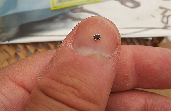
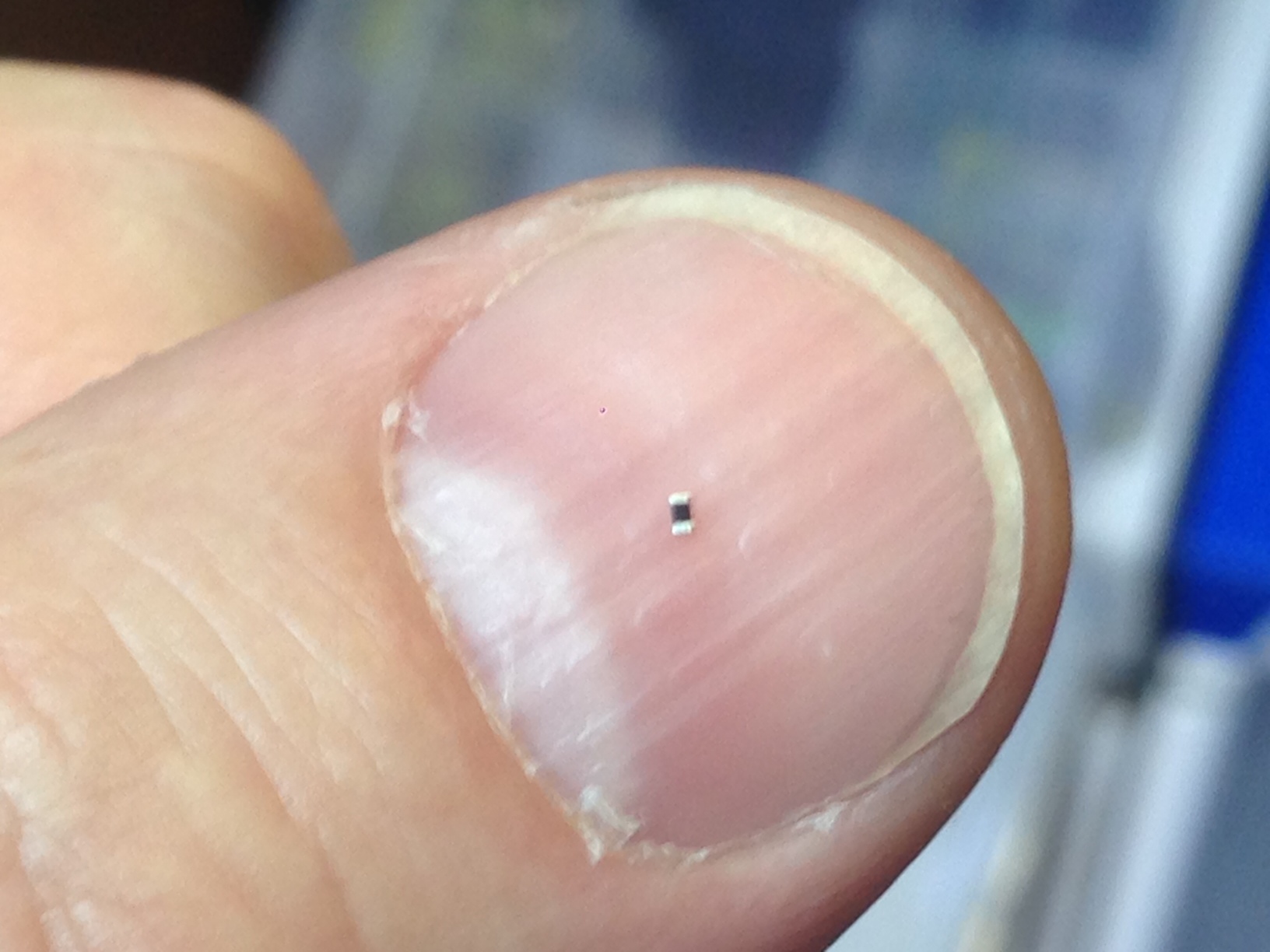
P.S. The temperature sensor from our board is even smaller in size. I'm soldering all them using regular china soldering iron
it is hard to imagine, it was hard to imagine for myself too just 6 month ago
also this I do :)
-
Great news! How and where will these be sold?
I got some sample boost chips from TI today, but soldering them seems hopeless and finding the recommended components isn't easy or cheap so I reckon this is a pretty good deal. And a lot easier to put into production than the whole battery powered board. Also, no need to update the design for this ever, should it work as intended.
Kudos for soldering this ...
@bjornhallberg said:
I got some sample boost chips from TI today, but soldering them seems hopeless.
I have not done this myself yet (this weekend it is my turn) but I found some excellent video's on the subject of soldering SMD's. Just google for 'soldering dmd' ( if you have not already done that :)
-
@bjornhallberg said:
I got some sample boost chips from TI today, but soldering them seems hopeless.
I have not done this myself yet (this weekend it is my turn) but I found some excellent video's on the subject of soldering SMD's. Just google for 'soldering dmd' ( if you have not already done that :)
@marceltrapman I'd be willing to give it a try, but the most immediate hurdle is finding the right capacitors and inductor. Finding small quantities cheaply has proven more hopeless than soldering. And the components you get on Ebay, could you ever trust them? Ceramic caps in the uF range turned out to be more expensive than I had anticipated etc etc ... therefore ... you'd be hard pressed to do it yourself for less than $5. Not to mention the work. Plus you have the 5V option that I never considered.
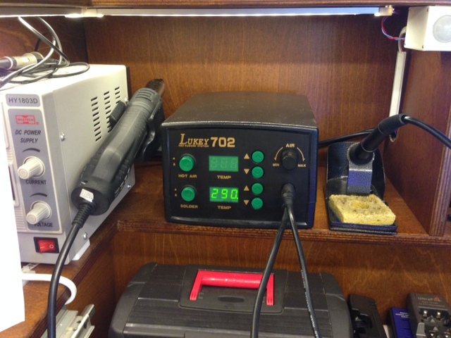
@axillent That is some crazy small chip! Just out of curiosity, where did you buy that soldering iron (because I need a new one as well, sigh).
-
@marceltrapman I'd be willing to give it a try, but the most immediate hurdle is finding the right capacitors and inductor. Finding small quantities cheaply has proven more hopeless than soldering. And the components you get on Ebay, could you ever trust them? Ceramic caps in the uF range turned out to be more expensive than I had anticipated etc etc ... therefore ... you'd be hard pressed to do it yourself for less than $5. Not to mention the work. Plus you have the 5V option that I never considered.
@axillent That is some crazy small chip! Just out of curiosity, where did you buy that soldering iron (because I need a new one as well, sigh).
@axillent That is some crazy small chip! Just out of curiosity, where did you buy that soldering iron (because I need a new one as well, sigh).
I purchased it at local store
surprisingly some goods are cheaper to buy locally than from ebay or ali
it is a complete soldering station at a value of about $90
-
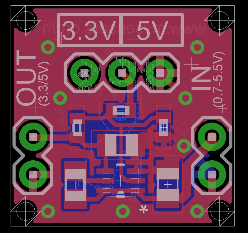
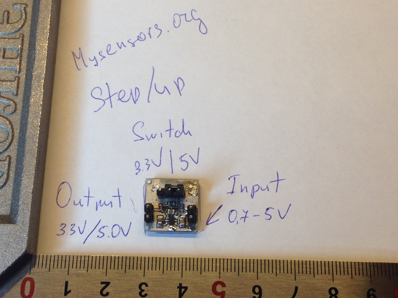
Through a discussion on the forum we found a potential interest to the step-up module with excellent battery saving capabilities
We decided to present to you such a module
It is actually same technology as will be used for MySensors Battery board, but it allows to choose any other board for your battery operated project.
Module is using one of the best in class chip with hight efficiency and low quiescent current, this allows to run your device for longer time
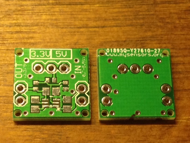
Module is designed with standard 2.54 pitch connector, can be easily connected using dupon wires
Output voltage can be selected by switch 3.3V or 5V
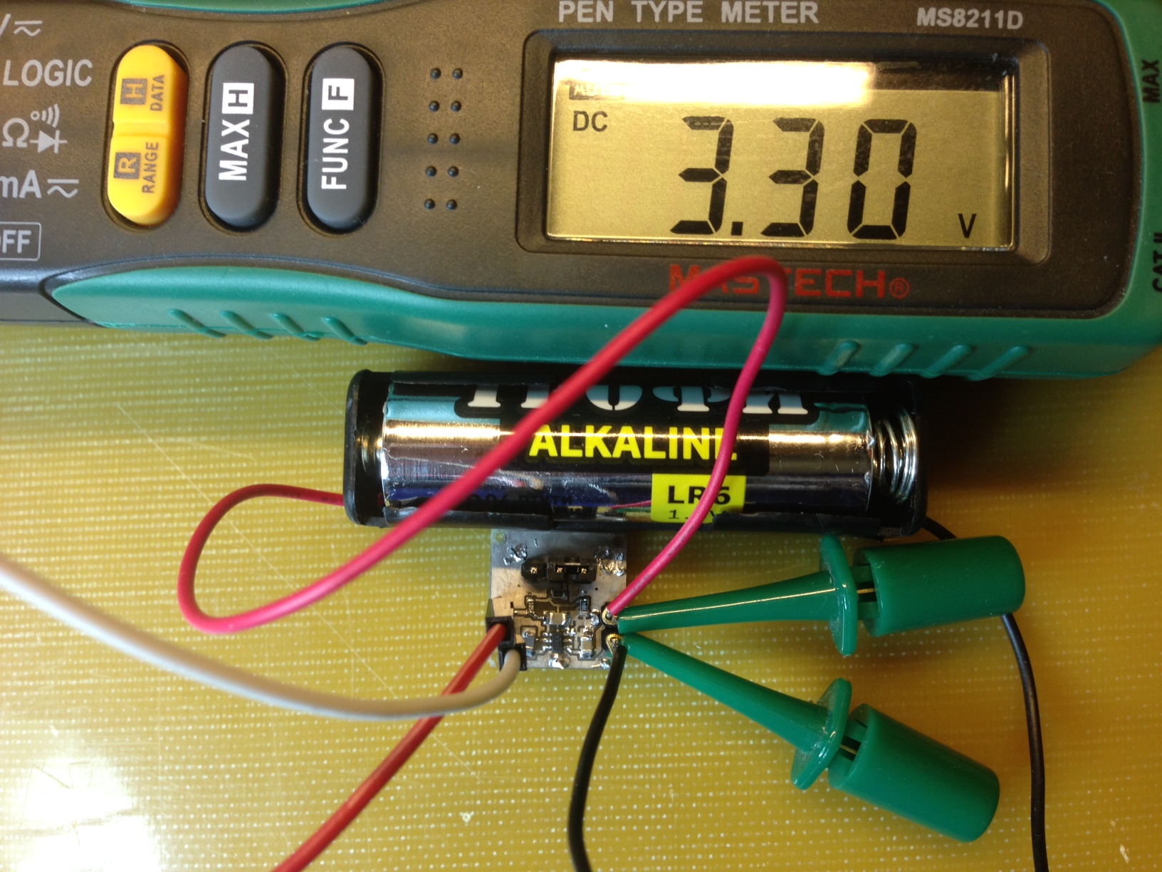
As power source you can use:- for 3.3V output - 1-2 alkaline, 1-3 NiMh/NiCd or solar up to 3.3V
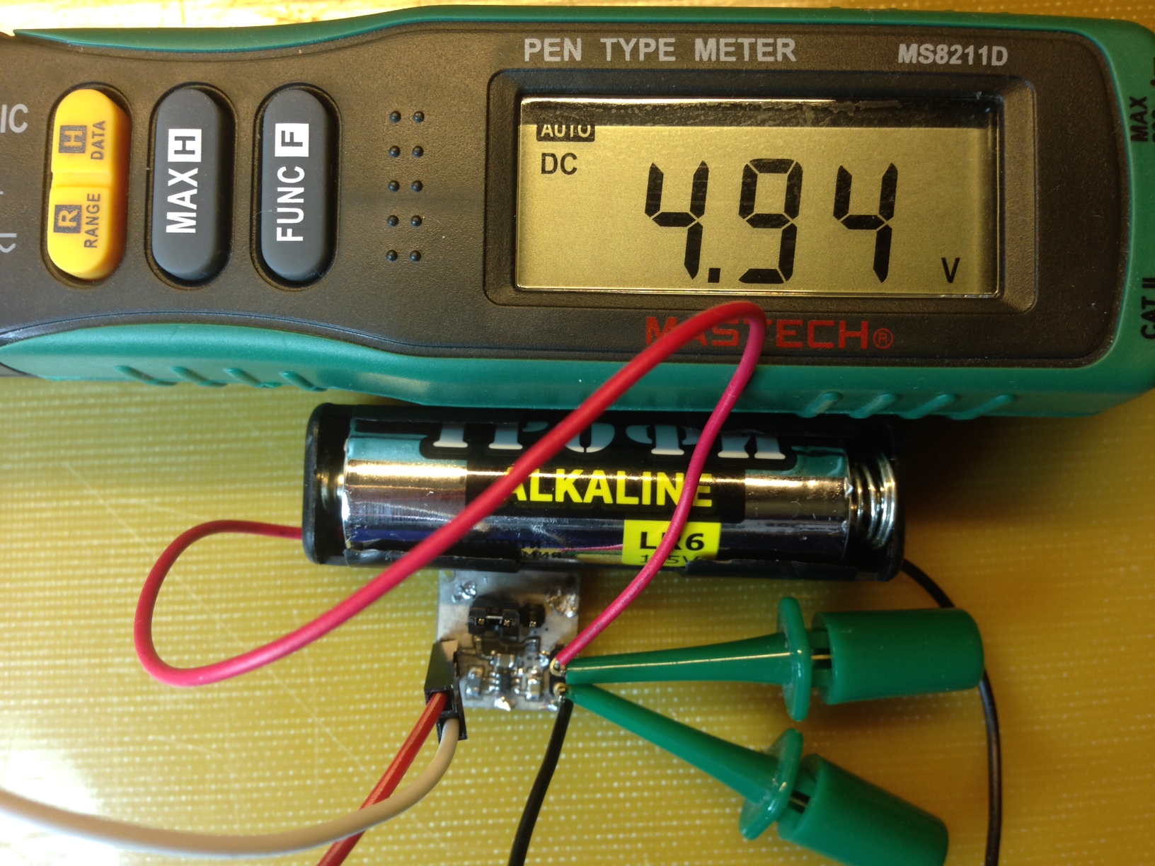
- for 5V - 1-3 alkaline, 1-4 NiMh/NiCd or solar up to 5V
100mA output for 3.3V or 70mA for 5V are at minimum guaranteed
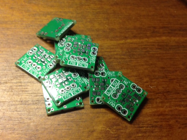
Size is just 15x15mm
Estimated retail price before shipping cost is $5
Anyone interested?Prototype is on photo fully tested
-
@axillent Did you do some measurements on the stability of the supply when powering an Arduino + radio?
-
@Yveaux what kind of stability you are interested in?
the output voltage will be stable while the source is able to source at a level above 0.7V@axillent There was a lot of discussion in another thread about radio troubles caused by fluctuations in power supply. Performance could be improved significantly by adding a capacitor to the supply of the radio. It would be nice if the whole could be powered by just this module, without requiring extra capacitors.
So, please do some tests with a radio connected running a mysensors sketch with your step-up module (or maybe the whole board once you connect the radio) and compare the results to when directly powered from batteries (without step-up). The range and amount of lost packets should be comparable. -
@axillent There was a lot of discussion in another thread about radio troubles caused by fluctuations in power supply. Performance could be improved significantly by adding a capacitor to the supply of the radio. It would be nice if the whole could be powered by just this module, without requiring extra capacitors.
So, please do some tests with a radio connected running a mysensors sketch with your step-up module (or maybe the whole board once you connect the radio) and compare the results to when directly powered from batteries (without step-up). The range and amount of lost packets should be comparable.@Yveaux
the need of the capacitor for radio is depends on how long are the wires (or PCB tracks) from power source to radiomy step-up module have a sufficient capacitor (good quality low ESR X7R) on the output
if wires will be not long there will be no need of an additional capacitor
otherwise an additional capacitor need to be soldered close to radioon Battery board I add a second capacitor for unquestionable performance
-
Through a discussion on the forum we found a potential interest to the step-up module with excellent battery saving capabilities
We decided to present to you such a module
It is actually same technology as will be used for MySensors Battery board, but it allows to choose any other board for your battery operated project.
Module is using one of the best in class chip with hight efficiency and low quiescent current, this allows to run your device for longer time
Module is designed with standard 2.54 pitch connector, can be easily connected using dupon wires
Output voltage can be selected by switch 3.3V or 5V
As power source you can use:- for 3.3V output - 1-2 alkaline, 1-3 NiMh/NiCd or solar up to 3.3V
- for 5V - 1-3 alkaline, 1-4 NiMh/NiCd or solar up to 5V
100mA output for 3.3V or 70mA for 5V are at minimum guaranteed
Size is just 15x15mm
Estimated retail price before shipping cost is $5
Anyone interested?Prototype is on photo fully tested
@axillent Looks like a much-needed part for our battery sensors. Is there any chance of moving the pins together to emulate the current step converter in the store? Ie, having three pins in a row: Vout GND Vin. This makes it a drop-in replacement for the existing part.
-
@Bandra said:
moving the pins together to emulate the current step converter in the store? Ie, having three pins in a row: Vout GND Vin. This makes it a drop-in replacement for the existing part.
Wow..Nice! Nice fingernails too...i could never photo mine...all chewed up!!! ;-)
With respect to the capacitior for the radio - i saw @axillent you are soldering a tantalum cap directly to the radio - i really like that method!
http://forum.mysensors.org/topic/185/battery-sensor-v-1-0-pcb/29Alex - i guess this chip cannot output both 3.3 and 5V at the same time, so would it be possible to have a module with two of these chips each one at 3.3 and the other at 5v ??
-Then it can be used for 5v sensors/devices.Greg
-
What is the chip used?
-
@axillent Looks like a much-needed part for our battery sensors. Is there any chance of moving the pins together to emulate the current step converter in the store? Ie, having three pins in a row: Vout GND Vin. This makes it a drop-in replacement for the existing part.
@Bandra said:
@axillent Looks like a much-needed part for our battery sensors. Is there any chance of moving the pins together to emulate the current step converter in the store? Ie, having three pins in a row: Vout GND Vin. This makes it a drop-in replacement for the existing part.
unfortunately there is no standard convention of this type. It is hard to match all different needs
input and output connectors are a generic tradeoff -
@Bandra said:
moving the pins together to emulate the current step converter in the store? Ie, having three pins in a row: Vout GND Vin. This makes it a drop-in replacement for the existing part.
Wow..Nice! Nice fingernails too...i could never photo mine...all chewed up!!! ;-)
With respect to the capacitior for the radio - i saw @axillent you are soldering a tantalum cap directly to the radio - i really like that method!
http://forum.mysensors.org/topic/185/battery-sensor-v-1-0-pcb/29Alex - i guess this chip cannot output both 3.3 and 5V at the same time, so would it be possible to have a module with two of these chips each one at 3.3 and the other at 5v ??
-Then it can be used for 5v sensors/devices.Greg
@gregl said:
Alex - i guess this chip cannot output both 3.3 and 5V at the same time, so would it be possible to have a module with two of these chips each one at 3.3 and the other at 5v ??
-Then it can be used for 5v sensors/devices.current draw from the battery is a multiplication from the stepup ratio
this means that current draw from the buttery with 5V output is 1.5 times higher comparing to 3.3V with the same current on the output
also current on the output much less depends on the voltage etc. MCU will draw 1-5mA regardless (with some extend) the VCC voltage
this leads into conclusion that as lower VCC used as better will be battery lifeIn my opinion 2.4V will be even more optimal for Battery board, but it is much more convenient to have 3.3V
While you need 5V you need to choose:
- best choice is to find all needed components able to work from 3.3V. For example PIR sensor is usually run from 4.5-20V. But there is no problem to purchase PIR running from 0.7-6V
- least optimal choice is to select 5V as a basic operation. This way you can use cheap LDO (like XC6206P332MR) to source radio
having two channels in stepup as you requested will double cost because you will need double number of components
and you always can use two universal modules simultaneously, one configured to 3.3V and other to 5V
-
Interested.. any ETA?
-
I'm finally back from a long trip
Sorry to be silentSeeed stepup boards are awaiting me at home.
Just need to run final performance tests
@axillent Fantastic! But they will come pre-soldered I hope :P
Hello! It looks like you're interested in this conversation, but you don't have an account yet.
Getting fed up of having to scroll through the same posts each visit? When you register for an account, you'll always come back to exactly where you were before, and choose to be notified of new replies (either via email, or push notification). You'll also be able to save bookmarks and upvote posts to show your appreciation to other community members.
With your input, this post could be even better 💗
Register Login