My Slim 2AA Battery Node
-
@ahmedadelhosni
I think it's a good idea! And an easy mod, but it's not on priority list atm. Someone else would get a quick start from my already published kicad-files.The thought behind present design is that I didn't want anything to cover the antenna in any direction, but I doubt it would matter much in this suggested case. It'll be worse when it comes to the hight. Look at the photos. The nRF becomes too high for my enclosures if I use a socket, and the 328p with its socket is too high to fit under a nRF without its socket. The solution would be to remove the 328p socket and move the R and Cs to bottom side or somewhere else. And without a 328p socket, the 3x2 AVR ISP pins would become more important to keep. Otherwise the board could have been trimmed even more.
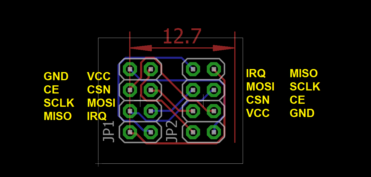
@m26872 Hi again. Just a small update regarding rotating the nrf.
I decided that in my designs I'll need the straight and rotated version, thus I'll design a small board to map the pin outputs like the image below. It will be above the ICSP pins but I really don't care about re flashing.
I'll order the board as soon as I finish pcb layout of some other boards and ship all at once.
Thanks.
-
@m26872 Hi again. Just a small update regarding rotating the nrf.
I decided that in my designs I'll need the straight and rotated version, thus I'll design a small board to map the pin outputs like the image below. It will be above the ICSP pins but I really don't care about re flashing.
I'll order the board as soon as I finish pcb layout of some other boards and ship all at once.
Thanks.
@ahmedadelhosni You know that the nRF pins are not centered? That means if you rotate it like this it will no longer be straight above the "slim node motherboard".
What height do you expect it to be? -
Another "noobish" question:
When using this bootloader, one cycle takes 8 seconds? What happens, if for example, a switch is pressed between? does this sensor detect this?Controller: Raspberry Pi 2 :: Openhab2 :: with @TimO MySensors Binding
Gateway: Arduino MEGA 2560 R3 :: W5100 :: Ethernet GWSoftware: MySensors 2.0development
-
Another "noobish" question:
When using this bootloader, one cycle takes 8 seconds? What happens, if for example, a switch is pressed between? does this sensor detect this?@dakky Plz correct me... but I guess you're talking about the Avr sleep cycles? I don't know what that's got to do with the bootloader or this thread. I think it's related to interrupt, timers, mysensors and arduino lowpower library. The sleep cycles shouldn't be something to worry about if you're using the "sleep" function as in MySensors API.
-
@dakky Plz correct me... but I guess you're talking about the Avr sleep cycles? I don't know what that's got to do with the bootloader or this thread. I think it's related to interrupt, timers, mysensors and arduino lowpower library. The sleep cycles shouldn't be something to worry about if you're using the "sleep" function as in MySensors API.
-
I had a bit of an issue getting things going as I've never played with the fuses before. Maybe this can save someone else some time. If I'm doing something silly here please correct me. :sweat_smile:
[DISCLAIMER] this worked for me. Use at own risk[DISCLAIMER]
Executed these commands from the subfolder \hardware\tools\avr\bin of my local arduino IDE.
Connected the board ICSP using an USBASP with the latest firmware. Change the "-c usbasp" part if you connect using something else.Flash bootloader
avrdude -C ../etc/avrdude.conf -c usbasp -B5 -p ATmega328P -U flash:w:..\..\..\arduino\avr\bootloaders\atmega\atmega328_1a.hexSet fuses
avrdude -C ../etc/avrdude.conf -c usbasp -B5 -p ATmega328P -U lfuse:w:0x62:m -U hfuse:w:0xDE:m -U efuse:w:0x07:m -U lock:w:0x2F:mI think the B5 was crucial as it slows things down a bit. The bootloader (atmega328_1a.hex) is the one mentioned in the first post. I also added the part in the boards.txt of the arduino IDE.
Now I can connect the board to the FTDI and upload and run sketches without issues.
On to the next step :smiley: :+1:
-
I am not so really skilled in transferring a wiring diagram to "real live". Is this the correct implementation for battery measuring?
Controller: Raspberry Pi 2 :: Openhab2 :: with @TimO MySensors Binding
Gateway: Arduino MEGA 2560 R3 :: W5100 :: Ethernet GWSoftware: MySensors 2.0development
-
I am not so really skilled in transferring a wiring diagram to "real live". Is this the correct implementation for battery measuring?
@dakky First, the "normal" battery monitoring to this node is to use the internal method by, if you like, using the vcc library. Measuring Vcc with external voltage divider makes not a lot of sense. The external voltage divider is useful when measuring e.g. raw battery voltage to some voltage regulator.
Second, I think you've switched A0 and Gnd in your drawing. -
Is there some one who have lying around several boards, who can share them with me.
i'm from the netherlands, and for now i only need 5 to 6 boards, not 30 :)so i hope i could take over a couple from someone.
-
Is there some one who have lying around several boards, who can share them with me.
i'm from the netherlands, and for now i only need 5 to 6 boards, not 30 :)so i hope i could take over a couple from someone.
@arnoldg said:
Is there some one who have lying around several boards, who can share them with me.
i'm from the netherlands, and for now i only need 5 to 6 boards, not 30 :)so i hope i could take over a couple from someone.
Same here, anybody in US has 4 or 5 boards that i could buy?
-
Anyone want to share some photos with sensors assembled?
Any experiences how long this node will last? I have one DHT11 and one BH1750 onboard and will wake up the node every 5-15 Minutes.Greetings
Dakky -
@nikos1671 If you buy the proto pack you could get 9,10 or 11 boards. It could be different that exactly 10 boards. In my case I received 12 boards for my design, in another order I received 11 boards. My last order was 10 boards. But in any case you will be able to make more then 25 sensors. Plenty for a normal house.
-
Anyone want to share some photos with sensors assembled?
Any experiences how long this node will last? I have one DHT11 and one BH1750 onboard and will wake up the node every 5-15 Minutes.Greetings
Dakky@dakky said:
Anyone want to share some photos with sensors assembled?
Any experiences how long this node will last? I have one DHT11 and one BH1750 onboard and will wake up the node every 5-15 Minutes.Greetings
DakkyI would like this too please! I'm trying to decide on which node to use as a motion sensor and temp/humidity sensor and would like to understand how I add a temp/humidty sensor to these and also the battery drain. And also, what temp/humidity sensors are we able to use with this node? I guess it ouputs max 3v, so does that mean the DHT11 and DHT22 are not able to be used here? Sorry for the newbie questions, I'm beginning to explore my options in relation to building my initial temp/humidity sensor and then a motion sensor.
edit OK, so based on what m26872 said here (http://forum.mysensors.org/topic/2715/slim-node-as-a-mini-2aa-battery-pir-motion-sensor/5) I think that I can only use Si7021 or HTU21 sensors as this outputs around 3v? From reading the spec sheet of the DHT11 and 22 I see they need 3.7v, so I guess if I want to use those sensors I need this node (http://forum.mysensors.org/topic/486/my-2aa-battery-sensor)?
-
@dakky said:
Anyone want to share some photos with sensors assembled?
Any experiences how long this node will last? I have one DHT11 and one BH1750 onboard and will wake up the node every 5-15 Minutes.Greetings
DakkyI would like this too please! I'm trying to decide on which node to use as a motion sensor and temp/humidity sensor and would like to understand how I add a temp/humidty sensor to these and also the battery drain. And also, what temp/humidity sensors are we able to use with this node? I guess it ouputs max 3v, so does that mean the DHT11 and DHT22 are not able to be used here? Sorry for the newbie questions, I'm beginning to explore my options in relation to building my initial temp/humidity sensor and then a motion sensor.
edit OK, so based on what m26872 said here (http://forum.mysensors.org/topic/2715/slim-node-as-a-mini-2aa-battery-pir-motion-sensor/5) I think that I can only use Si7021 or HTU21 sensors as this outputs around 3v? From reading the spec sheet of the DHT11 and 22 I see they need 3.7v, so I guess if I want to use those sensors I need this node (http://forum.mysensors.org/topic/486/my-2aa-battery-sensor)?
-
Humidity Sensor example
http://forum.mysensors.org/topic/3049/slim-node-si7021-sensor-example(This post used to contain a not yet finished design by mistake. The link above now shows the correct finished project.)