My Slim 2AA Battery Node
-
@Matt-Pitts - Not that hard if you read about it. Here are some good links:
-
-
@Tom71
well I have not yet started to use the Mysensor specific bootloader. When I use the optiboot, I upload sketch with my USBtiny (so no FTDI), and when I use FTDI for uploading sketch I used the "Arduino Pro or pro mini (3,3V, 8MHz) w/ATmega328"@bjacobse I thought the USBtiny is only to upload the bootloader, not the mysensors software.
I did two things:- Burn the bootloader atmega328_1a.hex to an bare Atmega328p with an Arduino as ISP
- Upload an simple scetch to the Atmega with an RX/TX uploader (I used an USB to TTL with an FTDI and also an Ardunino Uno without the Atmega chip, like here http://forum.mysensors.org/uploads/files/1454449901412-7.png) Both are working.
I'm still waiting for the PCB. After receiving I want to build the motion sensor.
-
@bjacobse I thought the USBtiny is only to upload the bootloader, not the mysensors software.
I did two things:- Burn the bootloader atmega328_1a.hex to an bare Atmega328p with an Arduino as ISP
- Upload an simple scetch to the Atmega with an RX/TX uploader (I used an USB to TTL with an FTDI and also an Ardunino Uno without the Atmega chip, like here http://forum.mysensors.org/uploads/files/1454449901412-7.png) Both are working.
I'm still waiting for the PCB. After receiving I want to build the motion sensor.
-
Difference is that if you use a ISP programmer you will use the complete memory. You can use ISP to upload a bootloader which is required to burn a sketch with ftdi into remaining memory but its possible to use a ISP to flash a sketch without bootloader as well.
-
Hi I'm just about to start ording parts of the slim node. Looking through the thread I'm thinking based on my limited knowledge of arduino, I might be better off buying chips which already have a bootloader installed?
Can people advise, how difficult is it to upload the boot loader? Thanks
@Matt-Pitts
Depending of your Arduino, the USBtiny is easy to use. Maybe your Aeduino have the pinheader so then only click the cable and burn bootloader. I use Arduino Pro Mini and have an adapter ZIF socket that fits my Arduino ProMini
https://learn.adafruit.com/usbtinyisp -
@bjacobse I'm out of fucus. What was the problem? Can you burn the bootloader+sketch with an USBtiny on an bare Atmgea328p? Connected on MISO/MOSI/SCK/RESET/VCC/GND?
The Arduino Pro Mini is different from the Atmgea328p. On the arduino is an external clock. -
@bjacobse I'm out of fucus. What was the problem? Can you burn the bootloader+sketch with an USBtiny on an bare Atmgea328p? Connected on MISO/MOSI/SCK/RESET/VCC/GND?
The Arduino Pro Mini is different from the Atmgea328p. On the arduino is an external clock.@Tom71
Can you burn the bootloader+sketch with an USBtiny on an bare Atmgea328p?
I have no idea - I have never tried this.
My originally point is that I have had similar problem to upload a sketch with a FTDI on an Arduino Pro Mini that have been flashed with Optiboot, and when flashed with a "normal" bootloader I could easily upload a sketch with FTDI. I mainly use Arduino Pro Mini 3,3V 8MHz...and that have the crystals etc in place -
@Tom71
Can you burn the bootloader+sketch with an USBtiny on an bare Atmgea328p?
I have no idea - I have never tried this.
My originally point is that I have had similar problem to upload a sketch with a FTDI on an Arduino Pro Mini that have been flashed with Optiboot, and when flashed with a "normal" bootloader I could easily upload a sketch with FTDI. I mainly use Arduino Pro Mini 3,3V 8MHz...and that have the crystals etc in place -
Board releases
(other colors might be selected when ordering)- Version 2.0 (black) [order] Now designed in KiCad. "Final release". I'm not developing it further atm, but I know others have some projects going.
- Version 1.4 (red) My latest version in Eagle. Known issues are wrong references due to panelization and broken circuit diagram links.
- Version 1.2 (blue) Some less convienient placed components and the panelized verision has a faulty via.
- Version 1.0 (green) The one described below in this first post. Working but not panelized and lacks a few features.
Share stats and info
The panelized versions 2.0, 1.4 and 1.2 have until today (2019-02-24) been shared 230 (!) times at boardhouse. Together with a few shares of the non-panelized version and my own orders, and the usual 3x10-11 boards/order, it means a lot of boards! Guess very few build nodes with every board, but at least the design should be well proven by now. This also means a few $ to MySensors.org, since 1 $/order will be donated. Great thanks to everyone who has orderd this board! I'll keep this share-info updated for transparency purposes. IMPORTANT: Please understand that DirtyPCBs.com is a non-profit community service, with a lot of manual support required. So please be patient and nice to their support in general. A new site is under development. Read more at their support site. EDIT 2017-06-22: Despite the new site it is still a hassle every time to get a reply from them and then the share credits. If anyone have some more info on this, please let me know.Introduction
This project describes a successor Node concept to my first 2AA battery sensor. I have combined a few simple design options to a result that I find rather useful myself and I think should be shared. The application specific sensor/-s of your own choice has to be added to this Node design, nor here any example sketches provided here except from a few links further below. I use this design for all my door and window reed switches, temperature (calibrated internal or thermistor), LDR and similar simple sensor types. But, nothing prevents the use of more sophisticated sensors like Si7021 here as well. A few links to sensor examples based on this node will be presented further down in this post.Features
- Simple, in the sense that it consists of a minimum number of components and common available material.
- Cheap regarding choice of components, assembly work effort, energy storage and power consumption (battery type and life time).
- Flexible universal design base equipped with various sensors. PCB pads used as port connections or prototyping area for extensions.
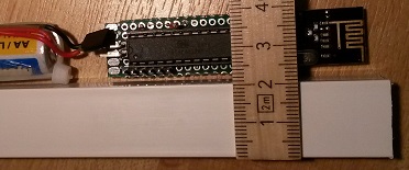
- Small and discrete to fit in confined spaces and to reach WAF level
And more concrete:
The uC
Hardware
A "bare bones" ATMega328p 28pin PDIP (with or without socket). Bought from here and here. My reasons to not use Arduino Pro Mini here are- The APM width is too big.
- APM has no prototyping/near connection area. There's no spare pads for separate connections unless you accept to use pads connected to softwise inactive ports.
- Radio module connection has to be manually made to the APM.
- Low power hacks like removing power led and voltage regulator are needed.
- Necessary support components (resistors and capacitors) are few and can easily be added to a custom pcb.
Software
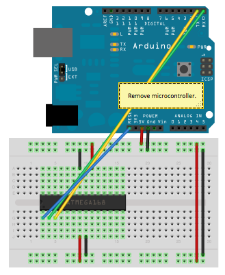
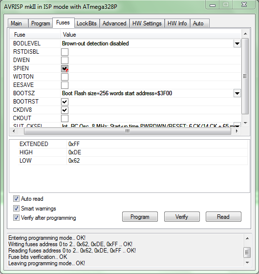
Since I prefer Arduino IDE for programming (flash) and debugging, I need a bootloader. Bootloader instructions are found all over the internet, but here's anyway how I do it. I use this precompiled bootloader from here. It's an Optiboot with 1MHz internal clock and 9600 baud serial communication. Fuse changed to BOD disable. According to this you should use minimal startup time to reduce power in every 8s sleep cycle, but for the moment I don't care and stick to the default 65ms. I use Avrisp mkII avr programmer for fuse and bootloading similar to this procedure. Arduino as ISP, Avr/USBtiny or whatever any other should of course be just as good. Avr Studio 4.19 is a good choice for Avrisp mkII (perhaps for others too) and 4.19 is the last version before the gigantic (and for me useless) IDEs were released.
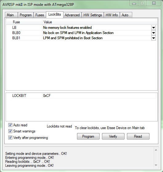
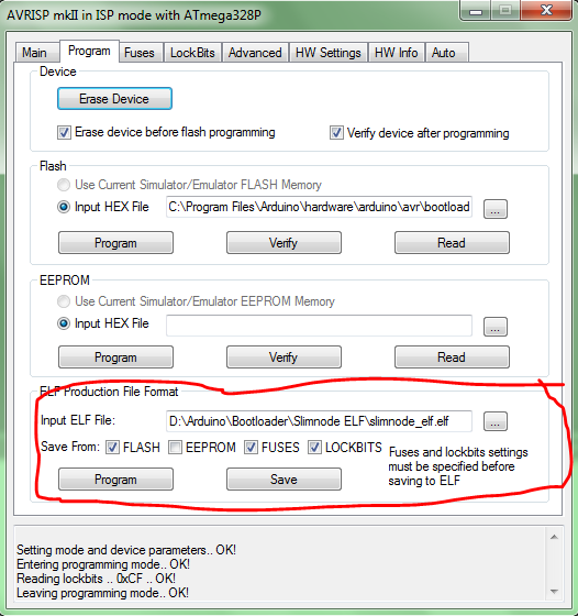
I add this new board to my "boards.txt". Fuse settings, don't forget to set the lock bits. If programming a large batch, the ELF production file is handy.
Here's a great tutorial for those who use Arduino Uno as ISP.
UPDATE 1: Today (2017) a lot has happen since I wrote about this. Some things has made it easier for us. A very good selection of precompiled bootloaders is now found here at MySensors. And you don't need to (and shouldn't) mess with the boards.txt any more. Instead I recommend the installation of MiniCore to the Arduino IDE.
UPDATE 2: There have been reported issues with MySensors 2.x freezing on SlimNodes running at 1MHz, which I've confirmed. Recommended solution when using MyS 2.x, is to use 8MHz (internal) instead.The Radio
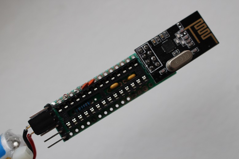
A standard NRF24L01+ radio module is used. The width align with the AAs and no mods is needed (like with my other one). As always I try to keep the antenna part of the module free from shading metal.
2020-12-14: On using RFM69 - here's a hint from @joaoabs at this page: I've been troubleshooting this slimnode with RFM69 radios and realized that a shunt between RFM69's DIO0 and Mega328's INT0 is required, otherwise the node will not "hear" the gateway. Even if the nrf2rmf69 board is used this shunt is required. It seems this is a re-current issueThe Board
At first I planned the build on a proto board, just to stick to the cheap-and-standard concept. But with today's low prices on custom made PCBs, it wasn't any longer an option. Space, quality and work effort are so much more attractive.
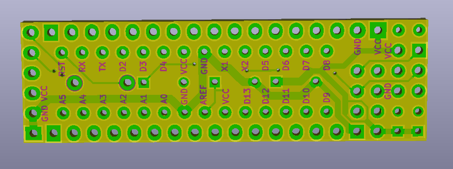
Latest design files are open and available at the openhardware.io site. Please click on the image-link below to access openhardware.io where all design files such as latest BOM, kicad-files and circuit diagram (pdf) are found.
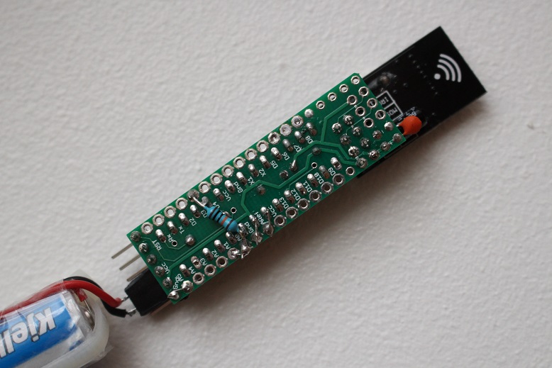
https://www.openhardware.io/view/10/My-Slim-2AA-Battery-NodeBoard (v2.0) Top Side:
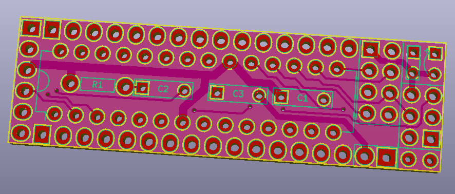
Board (v2.0) Bottom Side:
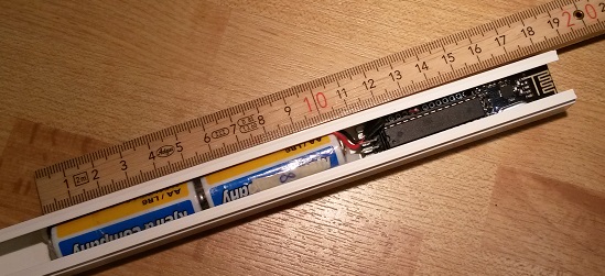
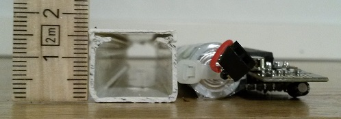
The Enclosure
UPDATE: If you dont't like my primitive casing descibed below, in this post the user @buxtronix made a nice 3D-printed case which you can find here.An important overall part of this design idea was to align minimum dimensions of the components and get rid of "expensive" parts like battery holder. It turn out (see below) that the enclosure's functionality as battery holder wasn't needed even though it was the initial idea. The cable duct case has been discussed earlier, but rejected by some due to lack of ways to seal the endings. I still haven't the perfect solution, but I've since many years simply used (cheap) white tape. With some care it looks ok, and still does 5-10 years later. There are often proper terminators/endings to buy, but for some reason to unrealistic high prices.
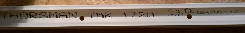
I used this cable duct with the dimension 17x20mm. Unfortunately it turned out that this particular type I used (Thorsman TMK T20) is now "professional grade" and dimension 17x20 is no longer very commercially available for consumers (here in Sweden at least). Eg. to get it, you have to pay >5$/m from places like this or buy it in bulk (50m) from a professional store (preferably as a professional with discount). The 50m bulk batch will give you 263 sensor nodes of standard length (19cm).
Standard consumer dimension cable duct is e.g. 15x15mm from what I've seen. It'd be nice to design a 2AAA node in that one. If only there is a thin radio module? (Future project.)
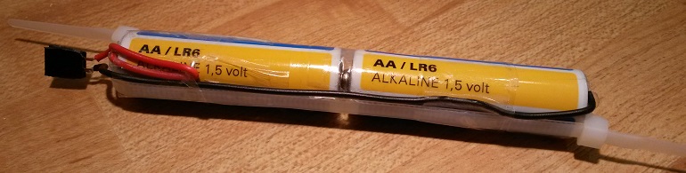
The Battery pack
Easy home made 2AA battery pack. Maybe it looks more demanding and time consuming than it is. (Usually its the other way around in my experience.)- Start by taping the two (connecting) batteries together.
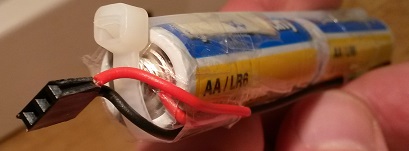
- Prepare the wires and make a small bun at the battery connecting ends.
- Attach the wires with tape.
- Tighten the cable ties and carefully note
- that the wires are pressed to make good contact with the battery poles
- how the cable tie ends must be placed to not steal lateral space
- that the wire from the bottom must be routed near the cable tie to not steal space.
- Make the pack more rigid by taping one or two times around at the top, bottom and middle.
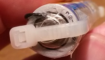
- Trim wires and solder the female connector. If desired, leave at least a small part of one wire naked for current measurements.
A battery change is done fast when cables a already made (use solid wires that preserves its shape). So why pay for a battery holder when you can remake a pack with fresh batteries in 1-2 min and your low power sensor will live 5-10 years before anything needs to be done?
The Interface/Connections
Convenient there's the 6 pin standard serial interface exactly like on the Arduino Pro Mini. Perhaps it's mirrored here, but I think everybody double checks Gnd and Vcc before connecting. The Vcc and Gnd pins also serves as a connector for the battery pack. (CTS is connected to GND on the PCB.)
"Under" the radiomodule are pads for the ICSP pins. The idea was to have a socket for the radiomodule instead of the "expensive" 328p socket and still have easy future access to the SPI/ICSP interface. Perhaps not very useful. But nice to have Gnd and Vcc in this end of the board for general purpose.The Sleep Mode Power Consumption
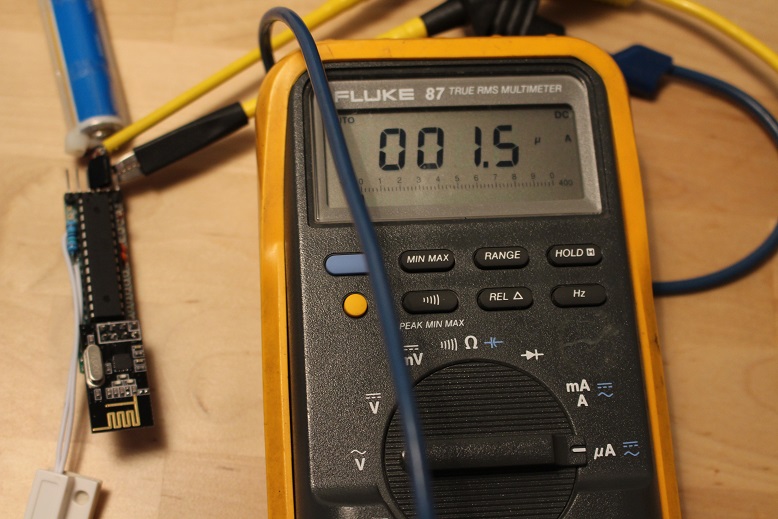
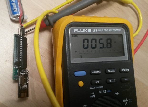
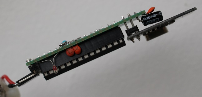
I measured the sleep mode current draw to be 1.5uA when it's set to interrupt wake up and 5.8uA when it's set to timer wake up.
Sensor Examples and more
Reed Switch Sensor: post 116
Humidity Sensor: Slim Node Si7021 sensor example
Motion Sensor 1: Slim Node as a Mini 2AA Battery PIR Motion Sensor
Motion Sensor 2: Slim CR123A (2AA) battery node..
Scene Controller: Slim Node scene controller/ keypad
(work in progress to collect more examples here)Not Sensor exemples, but some nice to see "node variations" from @AWI:
Here (post 88) and here (post 233). And now there's also @AWI 's My Slim 2AA Battery Node Tools.Still not "slim" enough? Check out Very Narrow and Minimal Switch Node ! by @GertSanders
And also, there's this 5V-slim-node a 5V-slim-node mod by @Soloam
Feature Requests
Here's a collection of suggestions and development ideas for future versions of the board (or other parts). If anyone else make their own board where some of this is included, I'd be happy to reference it from here.- Pin labels/references also on board top side.
- Turn the nRF footprint to make the assembly shorter.
- Make the board suitable for the nRF SMD version.
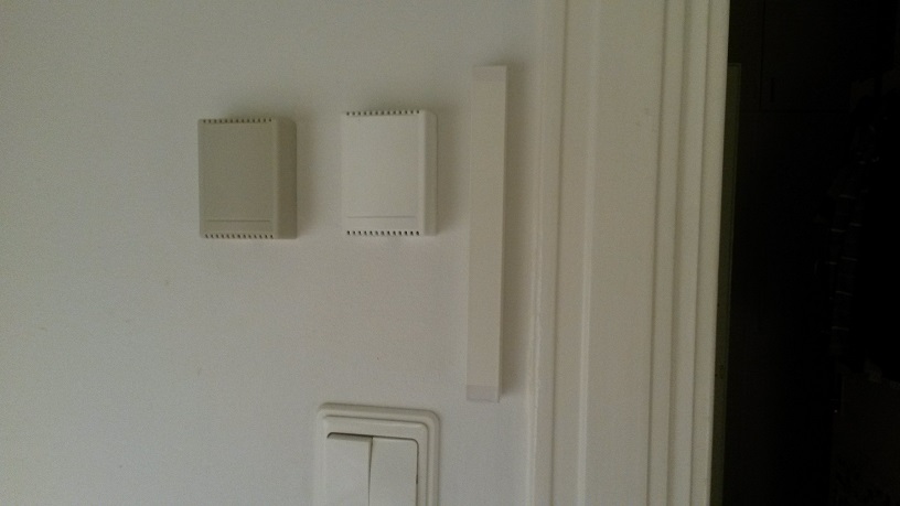
More Pictures
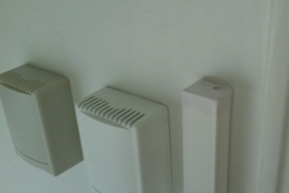
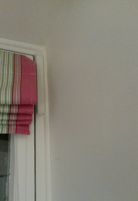
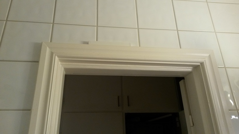
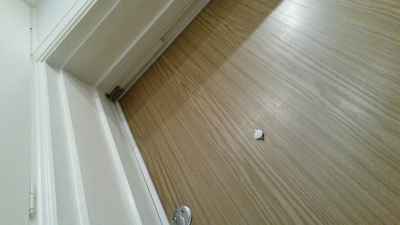
Some photos. First a comparison next to My (old) 2AA battery sensor, one painted and one not. (Note the high WAF of the colour even without the paint.) Then some placement examples. Reed switch nodes for all my doors and windows are my first priority.
I have ordered these. Hopefully they can get here soon-ish. All my prototyping is done and the WAF is dropping steadily with all the wires and components lying around.
One question on this - separating the individual boards from the panel: dremel tool with cuter blade fine? Or do I need to use some other method?
-
@wergeld I just make two small cuts from each side by a side cutter, then a gentle bend over some sharp edge like the table or a cutting board.
-
-
Just got a notification from DirtyPCB's that mine shipped - placed the order 9 days ago so give it some time. When I ordered mine, they were just re-opening from being closed for a week; I think it was Chinese new year or something.
@drock1985 Right. I waited until a week after Chinese new year to order. Let the hangovers end and the trainstations empty . I am looking forward to finalizing my sensor network with cases as well. I have several old plastic/wood boxes lying around waiting for a less rats-nest setup.
-
now I finally set up my first sensor board, and, as expected, I don´t receive any data from it on my gateway :suspect:
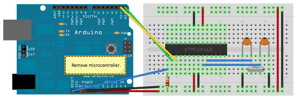
I uploaded the sketch following the instructions from here: https://www.arduino.cc/en/Tutorial/ArduinoToBreadboard using a 16MHz Crystal.
The sketch should run, but it doesn´t. Any ideas how to troubleshoot now?
edit: I opened the serial monitor after I uploaded the sketch using the mwthod mentioned above and I get the message "radio init fail".
The same sketch works on my UNO and I have no radio problem.Do I have to upload the sketch without the 16MHz Crystal to get it work proper?
still learning...
-
now I finally set up my first sensor board, and, as expected, I don´t receive any data from it on my gateway :suspect:
I uploaded the sketch following the instructions from here: https://www.arduino.cc/en/Tutorial/ArduinoToBreadboard using a 16MHz Crystal.
The sketch should run, but it doesn´t. Any ideas how to troubleshoot now?
edit: I opened the serial monitor after I uploaded the sketch using the mwthod mentioned above and I get the message "radio init fail".
The same sketch works on my UNO and I have no radio problem.Do I have to upload the sketch without the 16MHz Crystal to get it work proper?
-
I just installed the NRF module at it´s desired place as well as the two capacitors and the resistors as described above. The crystal is only used for uploading the sketch to the Atmega328 chip, described here: https://www.arduino.cc/en/Tutorial/ArduinoToBreadboard
So a wiring issue should not be the problem. Also, the code should have been uploaded well, because when I put the chip back to the breadboard and fire up my Arduino I at least receive the "radio init fail" message.
I just wonder if you guys upload your sketches the same way or if you use a different setup. I know there is a way to upload the sketch without the 16MHz crystal and I would like to know if this could be the problem.
edit: I´ve re-read your first post and also this thread http://forum.mysensors.org/topic/3018/tutorial-how-to-burn-1mhz-8mhz-bootloader-using-arduino-ide-1-6-5-r5/2 ...
Do I have to burn the bootloader using 1MHz or 8 MHz? I don´t get why this makes a difference, only that the batteries would drain faster the higher the MHz rate is.
I already uploaded a bootloader on my chips with a 16MHz crystal. Could I just re-upload a new bottloader using 1 or 8 MHz and overwrite the 16MHz bootloader?
still learning...
-
I just installed the NRF module at it´s desired place as well as the two capacitors and the resistors as described above. The crystal is only used for uploading the sketch to the Atmega328 chip, described here: https://www.arduino.cc/en/Tutorial/ArduinoToBreadboard
So a wiring issue should not be the problem. Also, the code should have been uploaded well, because when I put the chip back to the breadboard and fire up my Arduino I at least receive the "radio init fail" message.
I just wonder if you guys upload your sketches the same way or if you use a different setup. I know there is a way to upload the sketch without the 16MHz crystal and I would like to know if this could be the problem.
edit: I´ve re-read your first post and also this thread http://forum.mysensors.org/topic/3018/tutorial-how-to-burn-1mhz-8mhz-bootloader-using-arduino-ide-1-6-5-r5/2 ...
Do I have to burn the bootloader using 1MHz or 8 MHz? I don´t get why this makes a difference, only that the batteries would drain faster the higher the MHz rate is.
I already uploaded a bootloader on my chips with a 16MHz crystal. Could I just re-upload a new bottloader using 1 or 8 MHz and overwrite the 16MHz bootloader?
@siod The lowered MHz is not to drain battery slower. To save power we want to run wihtout buck- or boost (step-up or step-down) voltage regulators. When we do that, we need to ensure all circuit components work in whole battery voltage range. A good trade-off/design is then to make the Atmega work down to the same lower limit as the nRF24L01+, which is ~1.9V. Unfortunately the Atmega is unstable at high frequencies with low voltages. That why we need a low frequency. An external 4MHz should be low enough, but an easier, cheaper and usually good enough solution is to by the ATmega "fuse settings" activate an 8MHz internal crystal together with a "divide by 8" prescaler.
To fascilitate the use of noob-friendly Arduino IDE and concept of loading sketches and debug through a serial interface, we need to have a "bootloader" on the Atmega. The procedure you're referring to is how you put this bootloader to the ATmega. I would strongly recommend a beginner to start with ready made Arduinos in projects before starting to play with blank/bare ATmegas.
Whether you need the 16MHz crystal, 8MHz or none depends it's current fuse settings. Bootloader and fuse settings determine how you load, debug and run your sketch.
I think the guides, project threads, links and references provided here in the forum should be enough when you've come to the point where you can make it all the way.