My sensorboard MYS 1.0beta
-
The external pullups are for humidity sensor and 1-wire.
Yes there is a power plane and a ground plane under the radio. -
The ATmega has internal pull-ups on most IO. Is it not adequate to use those for pulls for I2C and sensors? Are they to weak?
-
The internal pullups is about 50K but for 1-wire and humidity you need a 4,7K ohm resistor.
-
Original thread got lost in the forumcrash.
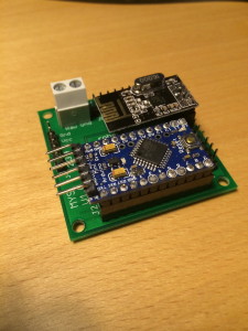
I have made a sensorboard that is under testing.
spec:
socket for arduino pro mini 5v/3,3V
socket for radio
3,3v regulator
4 AD input with voltage dividers
7 gpio availble with pullups on all pins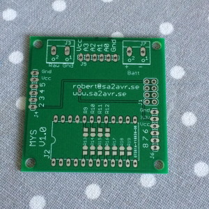
I have som small mods left to do in the voltage dividers.
Is there any interest in boards or kits (board + components) for just a few dollars?
-
I have updated the layout and added caps to the voltage dividers.
I am now going to order components for a batch of 100 boards.
what pull-up resistors and voltagedividers do you need?
I think that I will supply the kit with some 1K, 4,7k and 10K.
The price for a kit will probably be 7$ + shipping. Just add an Arduino pro mini, radio and sensor to make it a node.
@djdworks and @p0lar are first in line when they are ready.
@jendrush nice work. -
I have updated the layout and added caps to the voltage dividers.
I am now going to order components for a batch of 100 boards.
what pull-up resistors and voltagedividers do you need?
I think that I will supply the kit with some 1K, 4,7k and 10K.
The price for a kit will probably be 7$ + shipping. Just add an Arduino pro mini, radio and sensor to make it a node.
@djdworks and @p0lar are first in line when they are ready.
@jendrush nice work.@Mrlynx said:
nice work.
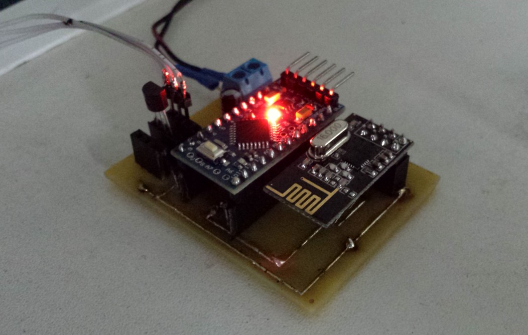
Thank you. This is only temperature board, but best part of this board is cost.
Piece of PCB ~30 cents,
pins ~30 cents,
power connector ~10 cents,
capacitor+resistor ~ 10 cents,
3.3V regulator ~ 10 cents
:) less than 1$ for complete board, and about 7$ for all parts including radio, arduino mini, wall usb charger, and cables:) This is power of MySensors!Thank you @Hek, and rest of the team!
-
Only problem is SDA and SCL are located on separate pins on top of the pro mini module and not in the normal row of pins. (A4-A5)
-
SDA and SCL seem to come in two places on APM's - inside the row of pins, and sometimes at the end opposite the serial programming pins. A host PCB could allow either.
-
I have now added SDA/SCL(A4/A5) to MYS 1.1
Is there any more ideas to be added before I send it for production? -
Well done I'm very happy for SDA and SCL added on the board thanks a lot.
Yesterday night I had a deeper look into the PCB and i was thinking that if you add 3 pins with MISO, MOSI and SCK your board will be good also to build ethernet gateway or connect additional SPI device.
-
I have thought about the spi channel but I cant really understand why the ethernet gateway sketch uses different CE/CS pins for the radio.
Why cant the radio use pin 9/10 and the ethernet shield 5/6?
Maybe @hek can shed som light on the matter? -
I have thought about the spi channel but I cant really understand why the ethernet gateway sketch uses different CE/CS pins for the radio.
Why cant the radio use pin 9/10 and the ethernet shield 5/6?
Maybe @hek can shed som light on the matter?It was based on an example I received from @a-lurker back in January.
If it is possible for someone to rework the example using the normal configuration for the radio and ethernet (WizNet and ENJ) on the 5/6 please post an updated EthernetGateway (1.4) and pin configuration in a new forum thread.
-
the CE and CS pin shall be different for each SPI you have connected on SPI bus.
The pins will act as follows
CE (chip enable) = with this pin, LOW or HIGH depending on the manufacturer, the SPI bus is connected like a switch to the device, when the device is not "connected to the bus" the pins will be in "high impedance" state. Sometimes CE is already connected with CS and is not available on device pinout.
CS (chip select) = this pin will enable the communication with the device.
I hope to have clarified the matter.
Some devices (like arduino TFT) have the possibility to have a dedicated SPI bus (MOSI MISO SCK CS RST) on any pin.
-
I have now added a SPI-header (SCK/MOSI/MISO) and a smd footprint for a 24LCXXX flash memory.
Hello! It looks like you're interested in this conversation, but you don't have an account yet.
Getting fed up of having to scroll through the same posts each visit? When you register for an account, you'll always come back to exactly where you were before, and choose to be notified of new replies (either via email, or push notification). You'll also be able to save bookmarks and upvote posts to show your appreciation to other community members.
With your input, this post could be even better 💗
Register Login