Skip to content
  • OpenHardware.io
  • Categories
  • Recent
  • Tags
  • Popular
Skins
  • Light
  • Brite
  • Cerulean
  • Cosmo
  • Flatly
  • Journal
  • Litera
  • Lumen
  • Lux
  • Materia
  • Minty
  • Morph
  • Pulse
  • Sandstone
  • Simplex
  • Sketchy
  • Spacelab
  • United
  • Yeti
  • Zephyr
  • Dark
  • Cyborg
  • Darkly
  • Quartz
  • Slate
  • Solar
  • Superhero
  • Vapor

  • Default (No Skin)
  • No Skin
Collapse
Brand Logo
  1. Home
  2. Hardware
  3. My sensorboard MYS 1.0beta
  • Getting Started
  • Controller
  • Build
  • Hardware
  • Download/API
  • Forum
  • Store

My sensorboard MYS 1.0beta

Scheduled Pinned Locked Moved Hardware
121 Posts 44 Posters 85.8k Views 13 Watching
  • Oldest to Newest
  • Newest to Oldest
  • Most Votes
Reply
  • Reply as topic
Log in to reply
This topic has been deleted. Only users with topic management privileges can see it.
  • Dan S.D Offline
    Dan S.D Offline
    Dan S.
    Hero Member
    wrote on last edited by
    #81

    Here are 2 pix of sensors I built using the boards.
    watersense.jpg
    TempHum.jpg

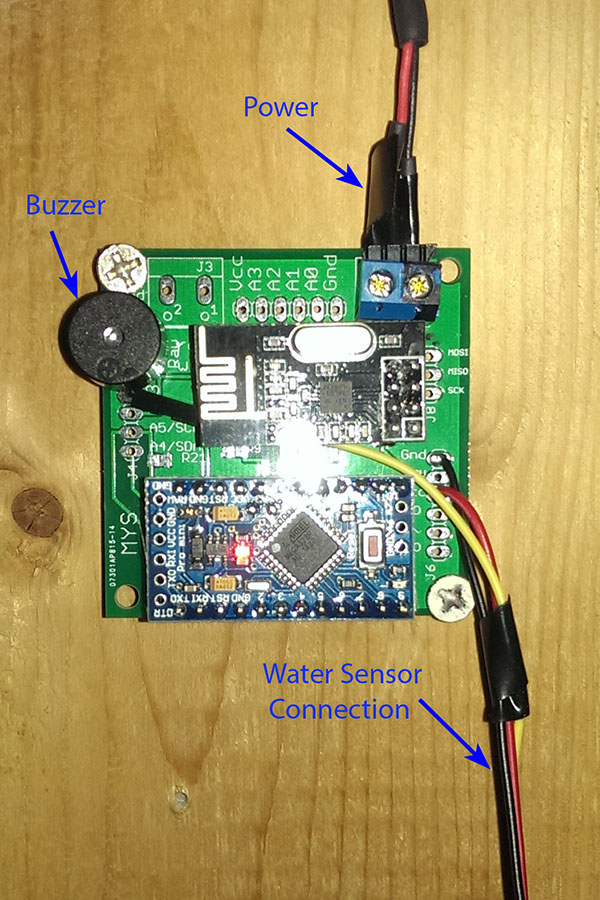
    The first is a water sensor/alarm which in addition to triggering the Vera controller, will activate a buzzer as a warning of a water leak in the basement water heater/furnace area.

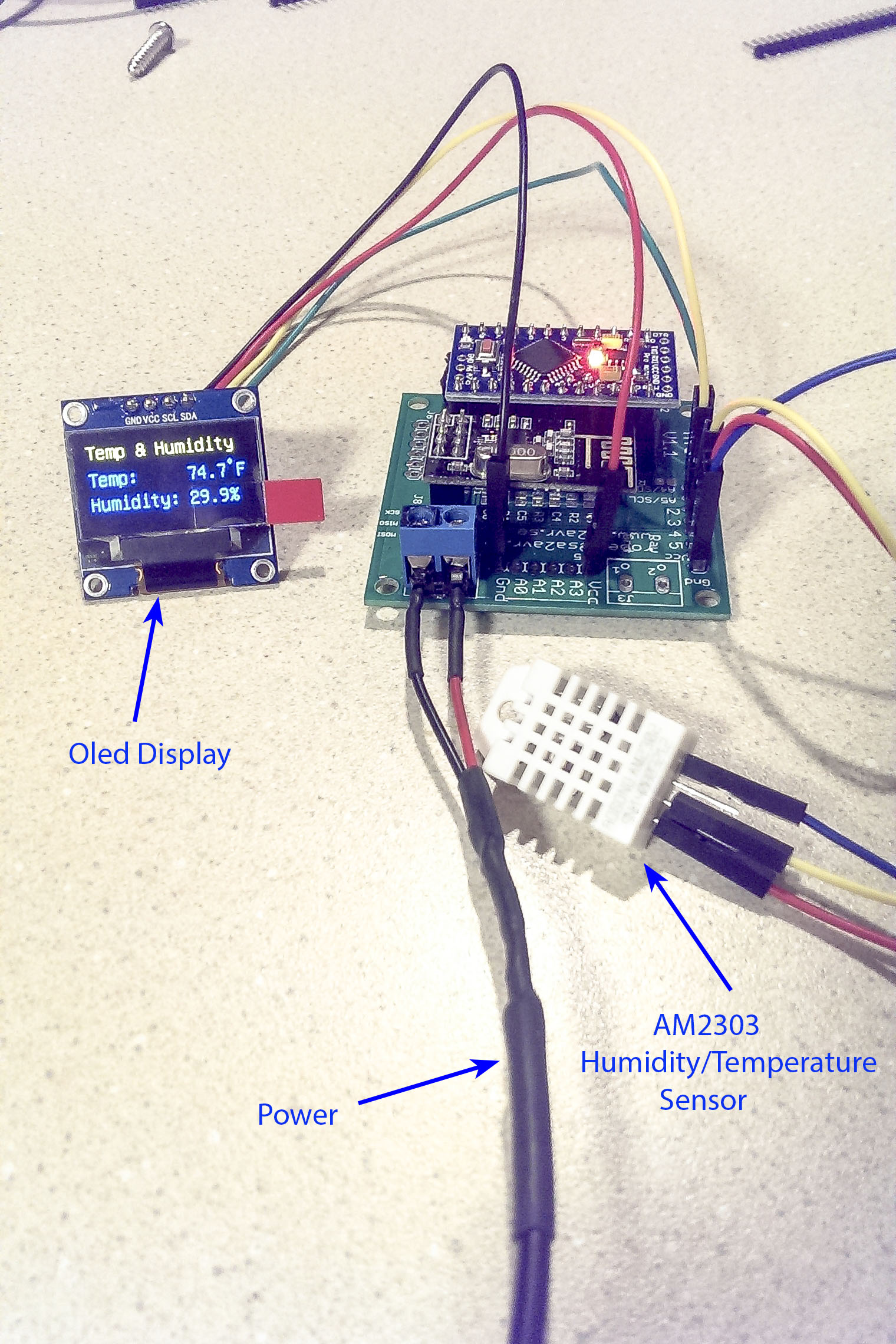
    The second is a standard temp/humidity sensor augmented with an Oled display readout. The display and sensor are temporarily hooked up until I decide where/how to mount them.

    1 Reply Last reply
    3
    • L Offline
      L Offline
      LaStrada
      wrote on last edited by
      #82

      Got the boards today. Thanks for fast shipping! :D

      1 Reply Last reply
      1
      • J Offline
        J Offline
        Joey Edelstein
        wrote on last edited by
        #83

        Hi,
        I ordered and received 5 kits' and am very happy to have them as last time I spent about 4 hr's soldering on to a prefboard.
        But given that I'm nearly a total newbie to electronics I am finding following the assembly instructions nearly impossible.
        Any chance somebody did a series of pictures while assembling that they can share? Or maybe a video of the process?
        Thanks in advance
        Joey

        1 Reply Last reply
        0
        • M Offline
          M Offline
          Mrlynx
          Hardware Contributor
          wrote on last edited by
          #84

          @Joey-Edelstein I will try to update the instruction with pictures as soon as possible.

          http://www.sa2avr.se

          1 Reply Last reply
          0
          • J Offline
            J Offline
            Joey Edelstein
            wrote on last edited by
            #85

            @Mrlynx thanks that will be a big help.

            1 Reply Last reply
            0
            • N Offline
              N Offline
              novicit
              wrote on last edited by
              #86

              @Mrlynx, last Saturday I received the 5 kits ordered from your web site, thanks! Nice simple board, and very flexible for different applications. Have assembled my first sensor using it and works perfectly. Don't miss all the wires it replaces. Although the 805 components are small, I prefer them to thru-hole. Again, thank you, and nice job! Love MySensors and the great community of support.

              1 Reply Last reply
              0
              • N Offline
                N Offline
                novicit
                wrote on last edited by
                #87

                @Joey-Edelstein , Here is what I did for assembly: Do not begin assembling the board until deciding on what the node is and selecting all parts - not all parts are needed. My first node is a DS18B20 temp sensor. 1) I wanted sockets for the radio and arduino so cut and put in pile of parts to be used. 2) I know I need D3 for the DS18B20, so I cut header for J4. Also need pull up resister for same, so look at the schematic for the board and you see R14 is the pull-up for D3. Put the resister in the pile of parts. 3) I also am battery powering the board, and want to measure it thru A0. So I cut header for J5. Also need a V divider, so looking at the schematic can do that with resisters on R12 & R4. Also need a small capacitor on C6. Put these parts on the pile. Collect all needed parts. Don't need header on J6 for example, not using it. 4) Also soldered the power cap on C2 - did not need the volt regulator supplied in the kit as I am feeding 3.3V directly to J7. Then solder the smallest components first starting with those closest to the center of the board, and moving out. Then the big components such as the sockets, again start at the center of the board and move out. Depending on your application, only use components needed. Look at the schematic. Hope this helps get you started.

                1 Reply Last reply
                0
                • SalmoidesS Offline
                  SalmoidesS Offline
                  Salmoides
                  wrote on last edited by
                  #88

                  @novicit, Thanks for the guidance. I just ordered some boards myself, and as a novice, your explanation will be very helpful to me as I plan out my sensors.

                  --
                  Sal

                  1 Reply Last reply
                  0
                  • S Offline
                    S Offline
                    Sorg
                    wrote on last edited by
                    #89

                    I have seen a MYSBootloader on the github . Is it specificallay related to this Board ?

                    hekH 1 Reply Last reply
                    0
                    • S Sorg

                      I have seen a MYSBootloader on the github . Is it specificallay related to this Board ?

                      hekH Online
                      hekH Online
                      hek
                      Admin
                      wrote on last edited by
                      #90

                      @Sorg

                      It is an optimized version (very reduced in size) done by the MYSController developer @tekka.

                      1 Reply Last reply
                      0
                      • J Offline
                        J Offline
                        Joey Edelstein
                        wrote on last edited by
                        #91

                        @novicit thanks for tips but my problem is I don't really know what all the parts in the kit are. I really need some pictures or video guidance...

                        1 Reply Last reply
                        0
                        • M Offline
                          M Offline
                          Mrlynx
                          Hardware Contributor
                          wrote on last edited by
                          #92

                          @Joey-Edelstein
                          Now the instruction page is update with some photos.

                          http://www.sa2avr.se

                          1 Reply Last reply
                          0
                          • J Offline
                            J Offline
                            jesper
                            wrote on last edited by
                            #93

                            Hi
                            Have a question.
                            if I want to buy YS1.1 pcb + components and YS1.1 pcb . How do I buy so only once shipping?

                            1 Reply Last reply
                            0
                            • M Offline
                              M Offline
                              Mrlynx
                              Hardware Contributor
                              wrote on last edited by
                              #94

                              @jesper Send me an email on robert@sa2avr.se

                              http://www.sa2avr.se

                              1 Reply Last reply
                              0
                              • M Offline
                                M Offline
                                Mrlynx
                                Hardware Contributor
                                wrote on last edited by
                                #95

                                MYS 1.1 pcb has now got a lower price.
                                If you by 5 or more boards the price is 2$ / board.
                                http://www.sa2avr.se/mys-1-1/

                                http://www.sa2avr.se

                                P 1 Reply Last reply
                                0
                                • M Mrlynx

                                  MYS 1.1 pcb has now got a lower price.
                                  If you by 5 or more boards the price is 2$ / board.
                                  http://www.sa2avr.se/mys-1-1/

                                  P Offline
                                  P Offline
                                  pboye
                                  wrote on last edited by
                                  #96

                                  @Mrlynx do you have a components list for resistors and capacitors, the schematic shows only r1 c1 not the values.

                                  Per Boye

                                  1 Reply Last reply
                                  0
                                  • M Offline
                                    M Offline
                                    Mrlynx
                                    Hardware Contributor
                                    wrote on last edited by
                                    #97

                                    @pboye look at http://www.sa2avr.se/mys-1-1/ under parts list.

                                    http://www.sa2avr.se

                                    P 1 Reply Last reply
                                    0
                                    • M Mrlynx

                                      @pboye look at http://www.sa2avr.se/mys-1-1/ under parts list.

                                      P Offline
                                      P Offline
                                      pboye
                                      wrote on last edited by
                                      #98

                                      @Mrlynx I ave seen that, but as i se it:

                                      First of all, this is a real nice project.

                                      r1-r4 : ?
                                      r5-r8 : ?
                                      r9-r12 : ?
                                      r13-21 : 4.7 K

                                      part list say's : R1-R21 10×4.7K (472) 4x1K (102) 4x10K (103) 4x120k(124), if you add the numbers it give 22 pices

                                      Per Boye

                                      1 Reply Last reply
                                      0
                                      • M Offline
                                        M Offline
                                        Mrlynx
                                        Hardware Contributor
                                        wrote on last edited by
                                        #99

                                        It all depends on what sensor or actuator you are going to connect.
                                        I chose a basic assortment of resistors to get you started and be able to build all examples on www.mysensors.org.
                                        As this question have come up before am I going to write down some examples on http://www.sa2avr.se

                                        http://www.sa2avr.se

                                        1 Reply Last reply
                                        0
                                        • A Offline
                                          A Offline
                                          activemind
                                          wrote on last edited by activemind
                                          #100

                                          Very useful PCB.
                                          Had a question before placing the order for the pcb.
                                          What is the pitch for the male/female headers and the screw terminals ?
                                          Is it 2.54 mm (0.1") for header and 5.08 mm (0.2") for terminals ?
                                          Thanks

                                          1 Reply Last reply
                                          0
                                          Reply
                                          • Reply as topic
                                          Log in to reply
                                          • Oldest to Newest
                                          • Newest to Oldest
                                          • Most Votes


                                          12

                                          Online

                                          11.7k

                                          Users

                                          11.2k

                                          Topics

                                          113.0k

                                          Posts


                                          Copyright 2019 TBD   |   Forum Guidelines   |   Privacy Policy   |   Terms of Service
                                          • Login

                                          • Don't have an account? Register

                                          • Login or register to search.
                                          • First post
                                            Last post
                                          0
                                          • OpenHardware.io
                                          • Categories
                                          • Recent
                                          • Tags
                                          • Popular