Domoticz 4 x relay
-
I wrote code to 4 relays:
#include <MySigningNone.h>
#include <MyTransportNRF24.h>
#include <MyTransportRFM69.h>
#include <MyHwATMega328.h>
#include <MySensor.h>
#include <SPI.h>

#define RELAY_1  3  // Pin D3
#define RELAY_2  4  // Pin D4
#define RELAY_3  5  // Pin D5
#define RELAY_4  6  // Pin D6
#define NUMBER_OF_RELAYS 4 // Liczba przekaznikow
#define RELAY_ON 1  // Stan wysoki przekaznik wlaczony
#define RELAY_OFF 0 // Stan niski przekaznik wylaczony

// NRFRF24L01 radio driver (set low transmit power by default)
MyTransportNRF24 radio(RF24_CE_PIN, RF24_CS_PIN, RF24_PA_LEVEL_GW);
//MyTransportRFM69 radio;
// Message signing driver (none default)
//MySigningNone signer;
// Select AtMega328 hardware profile
MyHwATMega328 hw;
// Construct MySensors library
MySensor gw(radio, hw);

void setup() {
  // Initialize library and add callback for incoming messages
  gw.begin(incomingMessage, AUTO, true);
  // Send the sketch version information to the gateway and Controller
  gw.sendSketchInfo("Relay", "1.0");

  // Fetch relay status
  for (int sensor=1, pin=RELAY_1; sensor<=NUMBER_OF_RELAYS;sensor++, pin++)
  for (int sensor=1, pin=RELAY_2; sensor<=NUMBER_OF_RELAYS;sensor++, pin++)
  for (int sensor=1, pin=RELAY_3; sensor<=NUMBER_OF_RELAYS;sensor++, pin++)
  for (int sensor=1, pin=RELAY_4; sensor<=NUMBER_OF_RELAYS;sensor++, pin++){
    // Register all sensors to gw (they will be created as child devices)
    gw.present(sensor, S_LIGHT);
    // Then set relay pins in output mode
    pinMode(pin, OUTPUT);
    // Set relay to last known state (using eeprom storage)
    digitalWrite(pin, gw.loadState(sensor)?RELAY_ON:RELAY_OFF);
  }
}


void loop()
{
  // Alway process incoming messages whenever possible
  gw.process();
}

void incomingMessage(const MyMessage &message) {
  // We only expect one type of message from controller. But we better check anyway.
  if (message.type==V_LIGHT) {
     // Change relay state
     digitalWrite(message.sensor-1+RELAY_1, message.getBool()?RELAY_ON:RELAY_OFF);
     // Store state in eeprom
     gw.saveState(message.sensor, message.getBool());
     // Write some debug info
     Serial.print("Incoming change for sensor:");
     Serial.print(message.sensor);
     Serial.print(", New status: ");
     Serial.println(message.getBool());
   }
}
Domoticz detected 4 switches
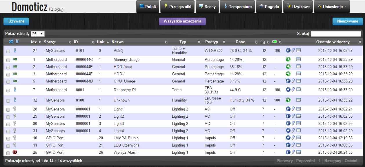
I added 4 switches in Domoticz
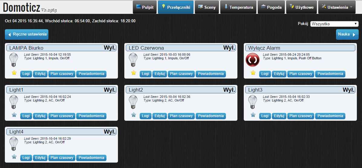
I connected the LED to pins 3,4,5,6 and when I turn on switch in Domoticz the LEDs do not want to turn on.
What is poorly written code?
-
I wrote code to 4 relays:
#include <MySigningNone.h>
#include <MyTransportNRF24.h>
#include <MyTransportRFM69.h>
#include <MyHwATMega328.h>
#include <MySensor.h>
#include <SPI.h>

#define RELAY_1  3  // Pin D3
#define RELAY_2  4  // Pin D4
#define RELAY_3  5  // Pin D5
#define RELAY_4  6  // Pin D6
#define NUMBER_OF_RELAYS 4 // Liczba przekaznikow
#define RELAY_ON 1  // Stan wysoki przekaznik wlaczony
#define RELAY_OFF 0 // Stan niski przekaznik wylaczony

// NRFRF24L01 radio driver (set low transmit power by default)
MyTransportNRF24 radio(RF24_CE_PIN, RF24_CS_PIN, RF24_PA_LEVEL_GW);
//MyTransportRFM69 radio;
// Message signing driver (none default)
//MySigningNone signer;
// Select AtMega328 hardware profile
MyHwATMega328 hw;
// Construct MySensors library
MySensor gw(radio, hw);

void setup() {
  // Initialize library and add callback for incoming messages
  gw.begin(incomingMessage, AUTO, true);
  // Send the sketch version information to the gateway and Controller
  gw.sendSketchInfo("Relay", "1.0");

  // Fetch relay status
  for (int sensor=1, pin=RELAY_1; sensor<=NUMBER_OF_RELAYS;sensor++, pin++)
  for (int sensor=1, pin=RELAY_2; sensor<=NUMBER_OF_RELAYS;sensor++, pin++)
  for (int sensor=1, pin=RELAY_3; sensor<=NUMBER_OF_RELAYS;sensor++, pin++)
  for (int sensor=1, pin=RELAY_4; sensor<=NUMBER_OF_RELAYS;sensor++, pin++){
    // Register all sensors to gw (they will be created as child devices)
    gw.present(sensor, S_LIGHT);
    // Then set relay pins in output mode
    pinMode(pin, OUTPUT);
    // Set relay to last known state (using eeprom storage)
    digitalWrite(pin, gw.loadState(sensor)?RELAY_ON:RELAY_OFF);
  }
}


void loop()
{
  // Alway process incoming messages whenever possible
  gw.process();
}

void incomingMessage(const MyMessage &message) {
  // We only expect one type of message from controller. But we better check anyway.
  if (message.type==V_LIGHT) {
     // Change relay state
     digitalWrite(message.sensor-1+RELAY_1, message.getBool()?RELAY_ON:RELAY_OFF);
     // Store state in eeprom
     gw.saveState(message.sensor, message.getBool());
     // Write some debug info
     Serial.print("Incoming change for sensor:");
     Serial.print(message.sensor);
     Serial.print(", New status: ");
     Serial.println(message.getBool());
   }
}
Domoticz detected 4 switches
I added 4 switches in Domoticz
I connected the LED to pins 3,4,5,6 and when I turn on switch in Domoticz the LEDs do not want to turn on.
What is poorly written code?
@romeok01 said:
for (int sensor=1, pin=RELAY_1; sensor<=NUMBER_OF_RELAYS;sensor++, pin++)
for (int sensor=1, pin=RELAY_2; sensor<=NUMBER_OF_RELAYS;sensor++, pin++)
for (int sensor=1, pin=RELAY_3; sensor<=NUMBER_OF_RELAYS;sensor++, pin++)
for (int sensor=1, pin=RELAY_4; sensor<=NUMBER_OF_RELAYS;sensor++, pin++){Is this really correct?
-
Where do you power the LED's from? In other words how did you connect them to the relays?
-
What I allways do during development is to uncomment the line #define DEBUG in MySensor.h that way MySensors is writing Debug info to your serial Monitor. It's getting late where I live and I need to go to bed. So I don't have time to dig into it.
But try this as your setup code
void setup() {
  // Initialize library and add callback for incoming messages
  gw.begin(incomingMessage, AUTO, true);
  // Send the sketch version information to the gateway and Controller
  gw.sendSketchInfo("Relay", "1.0");

  // Fetch relay status

  for (int sensor=1, pin=RELAY_1; sensor<=NUMBER_OF_RELAYS;sensor++, pin++){
    // Register all sensors to gw (they will be created as child devices)
    gw.present(sensor, S_LIGHT);
    // Then set relay pins in output mode
    pinMode(pin, OUTPUT);
    // Set relay to last known state (using eeprom storage)
    digitalWrite(pin, gw.loadState(sensor)?RELAY_ON:RELAY_OFF);
  }
}
Not sure if it helps but you can try it. I personally don't use gw.saveState a lot. The EPROM doesn't support unlimited write actions. So during development it's allways good to comment lines like that.