Office plant monitoring


  • @joshmosh , actually there is so many variables that it is impossible to check and the term "milage may vary" is spot on.
    All batteries are not the same.
    Temperature.
    Arduino.
    Time between readings (some batteries prefer small current over time and some handle bursts better).
    etc

    I've set to report moisture every 30 seconds and obviously the voltage report from an arduino is not 100%. And with that said, it is probably not 100% consistent neither as it could differ between readings as well.
    The only real way to tell is know starting point via multimeter and then check after a month what has happened.
    For me, doing a check, I've come down to 0.08V per 76000 readings.
    I did the estimation based on about 8500 readings and extrapolated it to 76000 reports based on @mfalkvidd information.

    For me, this is enough and I'm sure my sensor will survive for a long time and can now program it to take more reasonable moisture readings. Example, 1reading/h for the plots that dries the fastest (in direct sunlight) and less when they are in the shade.
    In the spring the balcony will have several sensors with automatic watering πŸ™‚


  • @Nicklas-Starkel
    After some reading and thinking, I came to a very similar conclusion. There are tons of parameter which will influence the mesurement.
    I am planning to use four or five moisture probes distributed at various places in my garden for irrigation automatisation. I guess my lawn will not suffer if I start watering at a reading of 41 % instead of 44 % πŸ˜‰
    During the upcoming winter months there is enough time to gather empirical data about the behaviour of my probes.
    Anyway, it's a fun project ...


  • Well I have some issues with battery-power.
    When ill use the Usb cable to power the sensor up, everything is working fine. But when ill use 2x1,5V batteryΒ΄s it does not show up in domoticz. Im not sure if I have connected the battery correct. Its on the VIN and GND and nothing more. Is it correct?


  • Mod

    @cattoo which Arduino are you using? I'm asking because the Pro Mini doesn't have any pin called VIN.


  • @mfalkvidd
    Its a Arduino Nano (clone)


  • Why not using this sensor?
    Giesomat

    It didn't cost much and work like an angel.

    And if the frequency is to high, or you need a other logic level, you can use this one:
    frequency divider and level shifter

    Don't have any troubles with this.
    I only count the pulses. That all.


  • Mod

    @NetRap You have already stated the same 3 times earlier in this thread. It looks like spam/advertising. What's your point?


  • Mod

    @cattoo VIN on the Nano is used when powering with higher than 5V.
    The Nano is not suitable for battery power. I recommend that you use a Pro Mini instead. See https://www.mysensors.org/build/battery


  • I don't want to spam.
    The point is, that the conducting based sensors are poison.
    The electrolytic processes destroy the sensor and giving ions into the
    earth !!!

    Look at this site:
    All Technologies
    There are compared all possible technology's.
    Giesomat wins.


  • @mfalkvidd said:
    Ah okey, well then ill use them with proper power and buy new pro miniΒ΄s instead. Tack πŸ™‚


  • Hello,

    Is there a sketch for mysensors 2.0
    I get error on the Mysensor gw;

    Ton


  • Just to give a feedback on power consumption: I have switched back to mysensors V 1.5.4. This was roughly one month ago. I take meadurements every two hours. Battery voltage hasn't changed a bit since then. So my guess is, that - for whatever reason - mysensors V 2.0 seems to produce a more power hungry code.
    Whatever ...
    I am happy now and will stick with V 1.5.4
    I am


  • @joshmosh I use MySensors V2 and took a sample every 30 seconds over a few days simulating almost 28000 transmits.
    I've come down to have roughly 0.08V decrease for all these transmits which is very close to what @mfalkvidd has.

    @TON-RIJNAARD , here is my sketch! I think I use signing as well, so if you don't use it just remove πŸ™‚

    // Enable debug prints to serial monitor
    #define MY_DEBUG
    //The node ID
    #define MY_NODE_ID 7 //250 is test 
    // Enable and select radio type attached and also set parent ID
    #define MY_RADIO_NRF24
    #define MY_PARENT_NODE_ID 0
    #define MY_PARENT_NODE_IS_STATIC
    //Signing, make sure the arduino is prepped for signing before!
    #define MY_SIGNING_SOFT
    #define MY_SIGNING_SOFT_RANDOMSEED_PIN 7
    #define MY_SIGNING_REQUEST_SIGNATURES
    #include <SPI.h>
    #include <MySensors.h>
    
    #define round(x) ((x)>=0?(long)((x)+0.5):(long)((x)-0.5))
    #define N_ELEMENTS(array) (sizeof(array)/sizeof((array)[0]))
    
    #define CHILD_ID_MOISTURE 0
    #define CHILD_ID_BATTERY 1
    #define SLEEP_TIME 1800000 // Sleep time between reads (in milliseconds)
    #define STABILIZATION_TIME 1000 // Let the sensor stabilize before reading
    #define BATTERY_FULL 3000 // 3,000 millivolts for 2xAA
    #define BATTERY_ZERO 2800 // 1,900 millivolts (1.9V, limit for nrf24l01 without step-up. 2.8V limit for Atmega328 without BOD disabled))
    const int SENSOR_ANALOG_PINS[] = {A0, A1}; // Sensor is connected to these two pins. Avoid A3 if using ATSHA204. A6 and A7 cannot be used because they don't have pullups.
    
    MyMessage msg(CHILD_ID_MOISTURE, V_HUM);
    MyMessage voltage_msg(CHILD_ID_BATTERY, V_VOLTAGE);
    long oldvoltage = 0;
    byte direction = 0;
    int oldMoistureLevel = -1;
    
    void setup()
    {
      sendSketchInfo("Plant moisture w bat", "1.5");
    
      present(CHILD_ID_MOISTURE, S_HUM);
      delay(250);
      present(CHILD_ID_BATTERY, S_CUSTOM);
      for (int i = 0; i < N_ELEMENTS(SENSOR_ANALOG_PINS); i++) {
        pinMode(SENSOR_ANALOG_PINS[i], OUTPUT);
        digitalWrite(SENSOR_ANALOG_PINS[i], LOW);
      }
    }
    
    void loop()
    {
      pinMode(SENSOR_ANALOG_PINS[direction], INPUT_PULLUP); // Power on the sensor
      analogRead(SENSOR_ANALOG_PINS[direction]);// Read once to let the ADC capacitor start charging
      sleep(STABILIZATION_TIME);
      int moistureLevel = (1023 - analogRead(SENSOR_ANALOG_PINS[direction]));
    
      // Turn off the sensor to conserve battery and minimize corrosion
      pinMode(SENSOR_ANALOG_PINS[direction], OUTPUT);
      digitalWrite(SENSOR_ANALOG_PINS[direction], LOW);
    
      direction = (direction + 1) % 2; // Make direction alternate between 0 and 1 to reverse polarity which reduces corrosion
      // Always send moisture information so the controller sees that the node is alive
    
      // Send rolling average of 2 samples to get rid of the "ripple" produced by different resistance in the internal pull-up resistors
      // See http://forum.mysensors.org/topic/2147/office-plant-monitoring/55 for more information
      if (oldMoistureLevel == -1) { // First reading, save value
        oldMoistureLevel = moistureLevel;
      }
      send(msg.set((moistureLevel + oldMoistureLevel +  0.5) / 2 / 10.23, 1));
      oldMoistureLevel = moistureLevel;
      long voltage = readVcc();
      if (oldvoltage != voltage) { // Only send battery information if voltage has changed, to conserve battery.
        send(voltage_msg.set(voltage / 1000.0, 3)); // redVcc returns millivolts. Set wants volts and how many decimals (3 in our case)
        sendBatteryLevel(round((voltage - BATTERY_ZERO) * 100.0 / (BATTERY_FULL - BATTERY_ZERO)));
        oldvoltage = voltage;
      }
      sleep(SLEEP_TIME);
    }
    
    long readVcc() {
      // From http://provideyourown.com/2012/secret-arduino-voltmeter-measure-battery-voltage/
      // Read 1.1V reference against AVcc
      // set the reference to Vcc and the measurement to the internal 1.1V reference
    #if defined(__AVR_ATmega32U4__) || defined(__AVR_ATmega1280__) || defined(__AVR_ATmega2560__)
      ADMUX = _BV(REFS0) | _BV(MUX4) | _BV(MUX3) | _BV(MUX2) | _BV(MUX1);
    #elif defined (__AVR_ATtiny24__) || defined(__AVR_ATtiny44__) || defined(__AVR_ATtiny84__)
      ADMUX = _BV(MUX5) | _BV(MUX0);
    #elif defined (__AVR_ATtiny25__) || defined(__AVR_ATtiny45__) || defined(__AVR_ATtiny85__)
      ADMUX = _BV(MUX3) | _BV(MUX2);
    #else
      ADMUX = _BV(REFS0) | _BV(MUX3) | _BV(MUX2) | _BV(MUX1);
    #endif
    
      delay(2); // Wait for Vref to settle
      ADCSRA |= _BV(ADSC); // Start conversion
      while (bit_is_set(ADCSRA, ADSC)); // measuring
    
      uint8_t low  = ADCL; // must read ADCL first - it then locks ADCH
      uint8_t high = ADCH; // unlocks both
    
      long result = (high << 8) | low;
    
      result = 1125300L / result; // Calculate Vcc (in mV); 1125300 = 1.1*1023*1000
      return result; // Vcc in millivolts
    }```


  • @Nicklas-Starkel
    Strange ...
    But since I am not missing / using any of the advanced features offered by V 2.0, I don't see a problem (at least for now) to stick with V 1.5.4
    In any case it is amazing what you can do with low power battery poweroperated sensors.


  • Hi,
    in last MySensors lib version 2.1.0, I see a new sensor type : S_MOISTURE
    It's more logicial to use this new type instead of S_HUM ?

    and so use V_LEVEL instead of V_HUM ?

    Thanks for respons


  • If I use more than one sensor for this. It still will only monitor one plant right? Or can I say monitor 3-4 plants with one node?


  • I have an arduino pro mini, connected to 2-3 flowers using A0+A1, A2+A3, A4+A5.. unfortunately, I'm seeing some weird effects between the plants.. if I water one plant, another can change a bunch at the same time (or not, depending on stuff).. Also if I disconnect one flower, another flower can get way different values too..

    I haven't figured out yet if I'm getting a capacitor effect in the flowers, sending back power through the output signals or what's happening..
    0_1483967302526_flower.png

    Here I added water to the "green" flower, then the values for the gray one dropped. The gray one was physically untouched while watering.

    Code is based on mfalkvidd, with all Ax being set to output=0 and then input+pullup for one while reading..


  • Mod

    @Stric interesting (and strange) effect. I wonder what causes it. Maybe the wait time beween turning on the pin and doing the measurement is too short so the level doesn't settle completely?


  • @Tetnobic i tried this and Ended up with a soil sensor that didn't display % but something called cb?

    But yeah it works.


  • I made a node with 1 fork and it works great!

    Any tips on how i can use more than one fork to monitor say 3-4 plants?


  • @mfalkvidd I'm going to do some tests with changing the sampling time and sleep time, but I'm not so hopeful since the effect is seen hours/days after an "unrelated" change.. I got stuck yesterday playing with ESPEasy, but I'll get back to debugging this..


  • @meanmrgreen See my post a few up, I'm seeing some weird effects when connecting to more than one plant..


  • @Stric

    Does reverse polarity really help with corrosion then? Maybe it has something to do with that.


  • Small problem with my plant sensor. Used only the fork and the reverse polarity.

    But the sensor is reporting around 80-70% all the time, alltho the plant is pretty dry.

    When i remove the sensor from pot it shows 0% ?

    Can you calibrate the fork somehow?


  • Mod

    @meanmrgreen I calibrate by putting my finger in the soil. When the soil is too dry I note the current value and set a notification to trigger next time it reaches that level.


  • @mfalkvidd

    Ok πŸ™‚
    But Its normal just to lower by a few percent in a few days time?


  • I'm going to try do this with the slim node and a cr2032 battery. Which cap do you recommend using to help battery?


  • Mod

    @meanmrgreen said:

    But Its normal just to lower by a few percent in a few days time?

    It depends on the soil type, the plant, the temperature, if the plant gets direct sunlight and probably some more factors.


  • I need to check my node. It Constantly shows 80-90%. Have switched forks and plant same number. If I pull it out of the dirt it gets to 0%

    Using only the fork no board in the middle with the alternate current sketch.


  • Re: Office plant monitoring
    Hello, i have build the sensor from the building page. I directly connect the fork to pin D6,D7. When i show the measurement i see strange values. anyone an idea what i did wrong?

    09.02.2017 19:22:23	Multi Sensor (multi2)	SoilMoistPercentageSensor	3 %
    09.02.2017 19:16:51	Multi Sensor (multi2)	SoilMoistPercentageSensor	0 %
    09.02.2017 19:11:20	Multi Sensor (multi2)	SoilMoistPercentageSensor	3 %
    09.02.2017 19:05:48	Multi Sensor (multi2)	SoilMoistPercentageSensor	5 %
    09.02.2017 19:00:17	Multi Sensor (multi2)	SoilMoistPercentageSensor	-1 %
    09.02.2017 18:54:46	Multi Sensor (multi2)	SoilMoistPercentageSensor	8 %
    09.02.2017 18:48:41	Multi Sensor (multi2)	SoilMoistPercentageSensor	5 %
    09.02.2017 18:43:10	Multi Sensor (multi2)	SoilMoistPercentageSensor	6 %
    09.02.2017 18:37:38	Multi Sensor (multi2)	SoilMoistPercentageSensor	1 %
    09.02.2017 18:32:07	Multi Sensor (multi2)	SoilMoistPercentageSensor	-1 %
    09.02.2017 18:26:36	Multi Sensor (multi2)	SoilMoistPercentageSensor	-1 %
    09.02.2017 18:21:04	Multi Sensor (multi2)	SoilMoistPercentageSensor	4 %
    09.02.2017 18:15:33	Multi Sensor (multi2)	SoilMoistPercentageSensor	4 %
    09.02.2017 18:10:02	Multi Sensor (multi2)	SoilMoistPercentageSensor	6 %
    09.02.2017 18:03:57	Multi Sensor (multi2)	SoilMoistPercentageSensor	6 %
    09.02.2017 17:58:26	Multi Sensor (multi2)	SoilMoistPercentageSensor	0 %
    09.02.2017 17:52:54	Multi Sensor (multi2)	SoilMoistPercentageSensor	6 %
    09.02.2017 17:46:50	Multi Sensor (multi2)	SoilMoistPercentageSensor	5 %
    09.02.2017 17:41:19	Multi Sensor (multi2)	SoilMoistPercentageSensor	-1 %
    09.02.2017 17:34:41	Multi Sensor (multi2)	SoilMoistPercentageSensor	6 %
    09.02.2017 17:29:10	Multi Sensor (multi2)	SoilMoistPercentageSensor	-3 %
    09.02.2017 17:23:39	Multi Sensor (multi2)	SoilMoistPercentageSensor	-11 %


  • @Dennis-van-der-Wolf

    Which sketch did you use? The one from this page needs the fork connected to analog input pins Ax.


  • @Jan-Gatzke I have connected the fork to A0 and A1 of mine arduino nano. Now i have this result:

    10.02.2017 12:17:35	Multi Sensor (multi2)	SoilMoistPercentageSensor	-182 %
    10.02.2017 12:12:04	Multi Sensor (multi2)	SoilMoistPercentageSensor	-455 %
    10.02.2017 12:06:33	Multi Sensor (multi2)	SoilMoistPercentageSensor	-317 %
    10.02.2017 12:01:02	Multi Sensor (multi2)	SoilMoistPercentageSensor	255 %
    10.02.2017 11:55:31	Multi Sensor (multi2)	SoilMoistPercentageSensor	-547 %
    10.02.2017 11:49:26	Multi Sensor (multi2)	SoilMoistPercentageSensor	1169 %
    10.02.2017 11:43:55	Multi Sensor (multi2)	SoilMoistPercentageSensor	40 %
    10.02.2017 11:38:24	Multi Sensor (multi2)	SoilMoistPercentageSensor	-250 %
    

    This is the sketch i use:

    /*
     * The MySensors Arduino library handles the wireless radio link and protocol
     * between your home built sensors/actuators and HA controller of choice.
     * The sensors forms a self healing radio network with optional repeaters. Each
     * repeater and gateway builds a routing tables in EEPROM which keeps track of the
     * network topology allowing messages to be routed to nodes.
     *
     * Created by Henrik Ekblad <henrik.ekblad@mysensors.org>
     * Copyright (C) 2013-2015 Sensnology AB
     * Full contributor list: https://github.com/mysensors/Arduino/graphs/contributors
     *
     * Documentation: http://www.mysensors.org
     * Support Forum: http://forum.mysensors.org
     *
     * This program is free software; you can redistribute it and/or
     * modify it under the terms of the GNU General Public License
     * version 2 as published by the Free Software Foundation.
     *
     *******************************
     *
     * DESCRIPTION
     *
     * Arduino soil moisture based on gypsum sensor/resistive sensor to avoid electric catalyse in soil
     *  Required to interface the sensor: 2 * 4.7kOhm + 2 * 1N4148
     *
     * Gypsum sensor and calibration:
     *    DIY: See http://vanderleevineyard.com/1/category/vinduino/1.html
     *    Built: Davis / Watermark 200SS
     *        http://www.cooking-hacks.com/watermark-soil-moisture-sensor?_bksrc=item2item&_bkloc=product
     *        http://www.irrometer.com/pdf/supportmaterial/sensors/voltage-WM-chart.pdf
     *        cb (centibar) http://www.irrometer.com/basics.html
     *            0-10 Saturated Soil. Occurs for a day or two after irrigation
     *            10-20 Soil is adequately wet (except coarse sands which are drying out at this range)
     *            30-60 Usual range to irrigate or water (except heavy clay soils).
     *            60-100 Usual range to irrigate heavy clay soils
     *            100-200 Soil is becoming dangerously dry for maximum production. Proceed with caution.
     *
     * Connection:
     *  D6, D7: alternative powering to avoid sensor degradation
     * A0, A1: alternative resistance mesuring
     *
     *  Based on:
     *  "Vinduino" portable soil moisture sensor code V3.00
     *   Date December 31, 2012
     *   Reinier van der Lee and Theodore Kaskalis
     *   www.vanderleevineyard.com
     * Contributor: epierre
     */
    
    // Copyright (C) 2015, Reinier van der Lee
    // www.vanderleevineyard.com
    
    // This program is free software: you can redistribute it and/or modify
    // it under the terms of the GNU General Public License as published by
    // the Free Software Foundation, either version 3 of the License, or
    // any later version.
    
    // This program is distributed in the hope that it will be useful,
    // but WITHOUT ANY WARRANTY; without even the implied warranty of
    // MERCHANTABILITY or FITNESS FOR A PARTICULAR PURPOSE.  See the
    // GNU General Public License for more details.
    
    // Enable debug prints to serial monitor
    #define MY_DEBUG
    
    // Enable and select radio type attached
    #define MY_RADIO_NRF24
    //#define MY_RADIO_RFM69
    
    #include <math.h>       // Conversion equation from resistance to %
    #include <MySensors.h>
    
    // Setting up format for reading 3 soil sensors
    #define NUM_READS 10    // Number of sensor reads for filtering
    #define CHILD_ID 0
    
    MyMessage msg(CHILD_ID, V_LEVEL);
    unsigned long SLEEP_TIME = 30000; // Sleep time between reads (in milliseconds)
    
    long buffer[NUM_READS];
    int index;
    
    /// @brief Structure to be used in percentage and resistance values matrix to be filtered (have to be in pairs)
    typedef struct {
        int moisture; //!< Moisture
        long resistance; //!< Resistance
    } values;
    
    const long knownResistor = 4700;  // Constant value of known resistor in Ohms
    
    int supplyVoltage;                // Measured supply voltage
    int sensorVoltage;                // Measured sensor voltage
    
    values valueOf[NUM_READS];        // Calculated moisture percentages and resistances to be sorted and filtered
    
    int i;                            // Simple index variable
    
    void setup()
    {
        // initialize the digital pins as an output.
        // Pin 6,7 is for sensor 1
        // initialize the digital pin as an output.
        // Pin 6 is sense resistor voltage supply 1
        pinMode(6, OUTPUT);
    
        // initialize the digital pin as an output.
        // Pin 7 is sense resistor voltage supply 2
        pinMode(7, OUTPUT);
    }
    
    void presentation()
    {
        sendSketchInfo("Soil Moisture Sensor Reverse Polarity", "1.0");
        present(CHILD_ID, S_MOISTURE);
    }
    
    void loop()
    {
    
        measure(6,7,1);
        Serial.print ("\t");
        Serial.println (average());
        long read1 = average();
    
        measure(7,6,0);
        Serial.print ("\t");
        Serial.println (average());
        long read2= average();
    
        long sensor1 = (read1 + read2)/2;
    
        Serial.print ("resistance bias =" );
        Serial.println (read1-read2);
        Serial.print ("sensor bias compensated value = ");
        Serial.println (sensor1);
        Serial.println ();
    
        //send back the values
        send(msg.set((long int)ceil(sensor1)));
        // delay until next measurement (msec)
        sleep(SLEEP_TIME);
    }
    
    void measure (int phase_b, int phase_a, int analog_input)
    {
        // read sensor, filter, and calculate resistance value
        // Noise filter: median filter
    
        for (i=0; i<NUM_READS; i++) {
    
            // Read 1 pair of voltage values
            digitalWrite(phase_a, HIGH);                 // set the voltage supply on
            delayMicroseconds(25);
            supplyVoltage = analogRead(analog_input);   // read the supply voltage
            delayMicroseconds(25);
            digitalWrite(phase_a, LOW);                  // set the voltage supply off
            delay(1);
    
            digitalWrite(phase_b, HIGH);                 // set the voltage supply on
            delayMicroseconds(25);
            sensorVoltage = analogRead(analog_input);   // read the sensor voltage
            delayMicroseconds(25);
            digitalWrite(phase_b, LOW);                  // set the voltage supply off
    
            // Calculate resistance
            // the 0.5 add-term is used to round to the nearest integer
            // Tip: no need to transform 0-1023 voltage value to 0-5 range, due to following fraction
            long resistance = (knownResistor * (supplyVoltage - sensorVoltage ) / sensorVoltage) ;
    
            delay(1);
            addReading(resistance);
            Serial.print (resistance);
            Serial.print ("\t");
        }
    }


    // Averaging algorithm
    void addReading(long resistance)
    {
        buffer[index] = resistance;
        index++;
        if (index >= NUM_READS) {
            index = 0;
        }
    }
    
    long average()
    {
        long sum = 0;
        for (int i = 0; i < NUM_READS; i++) {
            sum += buffer[i];
        }
        return (long)(sum / NUM_READS);
    }


  • Thanks for this great solution @mfalkvidd! It works great when my Arduino Pro Mini is connected to the computer, but not when I try to run it off a battery pack.

    I have a Pro Mini 3.3v connected to a 0.8-3.3v step up from a battery pack (2xAA; 3v). And then I have connected the radio and sensor to VCC on the Pro Mini. When the Pro Mini is connected to my iMac, Domoticz receives everything as it should. However, when I disconnect it from the computer and connect the battery source, all LEDs light as they should, indicitating that they have power, but it won't connect to Domoticz over NRF24.

    I have used a multimeter to check the voltage and if the radio receives enough power, and it does. All power/ground pins show around 3.3v. Any ideas to debug what's wrong?


  • @joshmosh said in Office plant monitoring:

    mfalkvidd

    Where i find mfalkvidd's sketch ?


  • Mod

    @ronnyandre a multimeter is unfortunately not sensitive enough to display if there is enough power during the short bursts when the radio is active.

    Most step-ups don't deliver power that is stable enough. You could try adding more/larger capacitors, but from what I have seen in the forum, people seldom get thing working reliably with a step-up. I have never tried using step-up myself, I use power directly from the batteries.

    If you haven't checked already, see the troubleshooting chart at https://forum.mysensors.org/topic/666/debug-faq-and-how-ask-for-help/


  • Mod

    Where i find mfalkvidd's sketch ?

    At github, but be aware that this code is for MySensors 1.x. It does not work with MySensors 2.x.


  • @mfalkvidd Thanks for the quick answer! I also read on the page for battery powered sensors that the step up generates alot of noise that can interfere with the radio, and that a solution might be to add capacitators (which I already tried), but also powering the radio directly from batteries. I'll try that later today. Thanks! πŸ˜ƒ

    And thank you for the link to the troubleshooting. It's now bookmarked! πŸ˜‰


  • Please somebody help me add to skech one relay for water pump. I use this in Domoticz. I do not want build other hardware for this.It is possible ?


  • Mod

    Just copy the relay code from https://www.mysensors.org/build/relay and add it your sketch and make necessary changes to adapt it: like setting child_id in presentation


  • @gohan I make something this. Please look if all is right. My software writer skill is low. πŸ™‚ Some small errors. πŸ™‚
    https://pastebin.com/8LWpgb8L


  • Mod

    because you are using old code, you need to convert it from libraries 1.5 to 2.x: there is a guide to do that


  • Can i use old libraries and gateway version 2.1 ?


  • Mod

    You can downgrade libraries and use old examples, but I'd suggest to stick to the new version


  • @gohan said in Office plant monitoring:

    but I'd suggest to stick to the new version

    I try but idonotknow. πŸ™‚


  • @gohan
    Please help with small errors. https://pastebin.com/VRXyT8Ut I try for library 2.x


  • It's a pity that at least one sketch for the analog reading of moisture sensor is not v2 compatible and made available on the main page ... i have no idea if making it v2 compatible would be a hard job...even if it's just a question of changing some library calls i'm afraid i don't have the skill for that...


  • Mod

    My Bonsai tree humidity node celebrates 2 years on battery today!

    During these two years, the gateway has received 146,528 updates on humidity level (and an additional 30,870 updates on voltage level).

    The battery level has gone from 3.187V to 3.049, which means an average drop of 0,0058V per month. Assuming I let it go down to 2.34V (limit for 8MHz according to the datasheet) and that the voltage drop is linear, I should get (3.187-2.34)/0.0058 = 146 months = ~12 years. There are several error sources in this calculation, but it looks like battery life will be quite good.

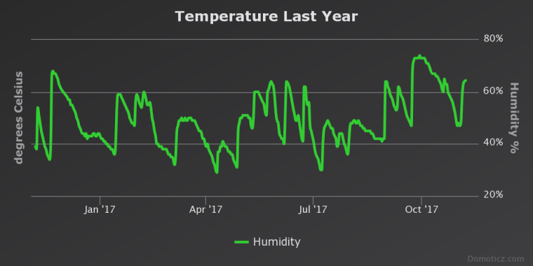
    Here are the voltage and humidity graphs for the last year.
    0_1510070572143_chart.png
    0_1510070578967_temp.png

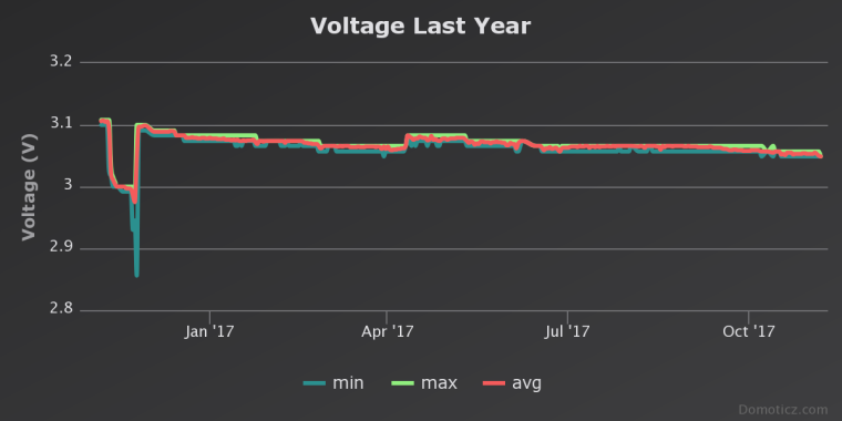
    As you can see, there was a problem in November. I was asked to verify the battery voltage reading by using a multimeter. When I opened the box to do that, I must have tripped something because the node got caught in some sort of loop, consuming battery. I restarted the node and the batteries recovered almost to the level they had before the problem occurred.

    Last year's report: https://forum.mysensors.org/post/52232


  • Mod

    @mfalkvidd said in Office plant monitoring:

    and that the voltage drop is linear

    You wish!!! πŸ˜„


  • Mod

    @gohan no actually I don't. The voltage drop is normally a s-shaped curve that is very flat in the middle. That means I am experiencing a higher drop at the beginning. That's likely the reason that the prediction after 2 years is more than 10% longer battery life than the prediction after 1 year was.


  • Mod

    Yes, it depends when the voltage starts to drop significantly, but unless you have tested another battery before it is hard to know in advance πŸ˜€


  • Mod

    @gohan alkaline batteries in general have been tested quite extensively and don't deviate much from the S-curve characteristics.


Log in to reply
 

Suggested Topics

  • 8
  • 2
  • 44
  • 2
  • 2
  • 1

0
Online

11.2k
Users

11.1k
Topics

112.5k
Posts