Managing interrupts from several sources
-
Hello,
I'm trying to build a mysensors node with several inputs (PIR sensors, reel switches, analogue humidity, etc.) and I would like to have it sleeping for most of the time except when some activity is detected (and every 15m or so, just to have a keep-alive). I'm using an arduino mini pro, at328, 8mhz, 3v.
Anyway, since D2 is reserved for mysensors future use of the NRF module, I just have the D3 to deal with interrupts.
I was thinking in performing a "logical OR" between all the sensor outputs and connect it to the D3, and then if any is activated, I can check all the other pins, one, by one. The simplest way of doing a "logical OR" is with diodes.My circuit is like this:
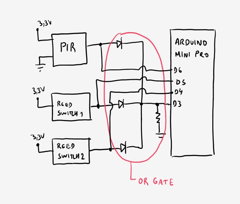
However this is not working, and I'm not so sure why. I've checked the code and it seems fine. Also the electric circuit should be theoretically correct, although I suspect something might be wrong there...
Whenever I activate one reed switch, an interrupt is raised, but when reading the ports, both are high.
I tested with a multimeter:
a) When in operation, if I activate one reed switch (to HIGH), the other gets also HIGH.
b) When in power-off, there is no continuity between the reed switch ports, so no apparent reason for thatThe diodes are schottky and the resistor is 1k.
Also, the PIR signal pin is behaving strangely.
The PIR module is modified to work at 3.3V (initial diode and 3.3v regulator bypassed).
If the PIR pin signal is not connected, it will go up to 3.3v when detecting presence. However, if connected to the arduino, it will never go beyond ~1.17v. This means that it will never be able to raise an interrupt and that the corresponding value in the arduino is always 0.Any idea why am I having this behaviour? My code below.
Thanks,
Joao#include <SPI.h> #include <MySensor.h> #define MOIST_SENSOR_A_ANALOG_PIN A1 #define MOIST_SENSOR_B_ANALOG_PIN A2 #define INTERRUPT 3-2 // dont know why, but somehow works #define DEBUG_SWITCH 4 #define DOOR_OPEN 5 #define PIR_SENSOR 6 #define TURN_ON_SWITCH 7 #define CHILD_ID_MOIST_SENSOR_A 1 #define CHILD_ID_MOIST_SENSOR_B 2 #define CHILD_ID_PIR_SENSOR 3 #define CHILD_ID_DOOR_OPEN_SENSOR 4 #define CHILD_ID_DEBUG_SWITCH 5 #define CHILD_ID_TEMP 6 #define CHILD_ID_HUM 7 unsigned long SLEEP_TIME = 30000; // Sleep time between reads (in milliseconds) MySensor gw; MyMessage msg_MOIST_SENSOR_A(CHILD_ID_MOIST_SENSOR_A, V_HUM); MyMessage msg_MOIST_SENSOR_B(CHILD_ID_MOIST_SENSOR_B, V_HUM); MyMessage msg_PIR_SENSOR(CHILD_ID_PIR_SENSOR, V_TRIPPED); MyMessage msg_DOOR_OPEN_SENSOR(CHILD_ID_DOOR_OPEN_SENSOR, V_TRIPPED); MyMessage msg_DEBUG_SWITCH(CHILD_ID_DEBUG_SWITCH, V_TRIPPED); // int lastHumLevel_A; int lastHumLevel_B; //BATTERY STUFF int BATTERY_SENSE_PIN = 0; // select the input pin for the battery sense point int oldBatteryPcnt = 0; void setup() { // use the 1.1 V internal reference #if defined(__AVR_ATmega2560__) analogReference(INTERNAL1V1); #else analogReference(INTERNAL); #endif gw.begin(); gw.sendSketchInfo("Nova placa", "1.0"); gw.present(CHILD_ID_MOIST_SENSOR_A, S_HUM, "HUM_A"); gw.present(CHILD_ID_MOIST_SENSOR_B, S_HUM, "HUM_B"); gw.present(CHILD_ID_PIR_SENSOR, S_MOTION, "PIR", true); gw.present(CHILD_ID_DOOR_OPEN_SENSOR, S_DOOR, "DOOR", true); gw.present(CHILD_ID_DEBUG_SWITCH, S_DOOR, "SWITCH", true); pinMode(INTERRUPT, INPUT); //digitalWrite(INT_PIN, HIGH); // turn on pullup resistor pinMode(DOOR_OPEN, INPUT); //digitalWrite(DOOR_OPEN, HIGH); // turn on pullup resistor pinMode(DEBUG_SWITCH, INPUT); //digitalWrite(DEBUG_SWITCH, HIGH); // turn on pullup resistor pinMode(PIR_SENSOR, INPUT); // sets the motion sensor digital pin as input //digitalWrite(PIR_SENSOR, HIGH); // turn on pullup resistor pinMode(TURN_ON_SWITCH, OUTPUT); } void loop() { digitalWrite(TURN_ON_SWITCH, HIGH); // TURN ON I2C devices (Future use) boolean tripped = digitalRead(PIR_SENSOR) == HIGH; boolean opened = digitalRead(DOOR_OPEN) == HIGH; boolean activated = digitalRead(DEBUG_SWITCH) == HIGH; Serial.println("\n----Starting loop----\n"); Serial.println("PIR value"); Serial.println(tripped); gw.send(msg_PIR_SENSOR.set(tripped?"1":"0"), true); // Send tripped value to gw Serial.println("\nDOOR_OPEN value:"); Serial.println(opened); gw.send(msg_DOOR_OPEN_SENSOR.set(opened?"1":"0"), true); // Send tripped value to gw Serial.println("\nDEBUG_SWITCH value:"); Serial.println(activated); gw.send(msg_DEBUG_SWITCH.set(activated?"1":"0"), true); // Send tripped value to gw int HumLevel_A = (1023-analogRead(MOIST_SENSOR_A_ANALOG_PIN))/7.5; Serial.print("\nHumidade_A: "); Serial.println(HumLevel_A); if (HumLevel_A != lastHumLevel_A) { gw.send(msg_MOIST_SENSOR_A.set(HumLevel_A)); lastHumLevel_A = HumLevel_A; } int HumLevel_B = (1023-analogRead(MOIST_SENSOR_B_ANALOG_PIN))/7.5; Serial.print("\nHumidade_B: "); Serial.println(HumLevel_B); if (HumLevel_B != lastHumLevel_B) { gw.send(msg_MOIST_SENSOR_B.set(HumLevel_B)); lastHumLevel_B = HumLevel_B; } //BATTERY STUFF // 1.2M, 121K divider across battery and using internal ADC ref of 1.1V // Sense point is bypassed with 0.1 uF cap to reduce noise at that point // ((1.2M+121k)/121k)*1.1 = Vmax = 12.00 Volts // 12/1023 = = Volts per bit = 0.011730205 int sensorValue = analogRead(BATTERY_SENSE_PIN); float batteryV = sensorValue * 0.011730205; int batteryPcnt = sensorValue / 10; Serial.print("\nBatery: "); Serial.print(sensorValue); Serial.println(" units (whatever they are)"); Serial.print("Battery Voltage: "); Serial.print(batteryV); Serial.println(" V"); Serial.print("Battery percent: "); Serial.print(batteryPcnt); Serial.println(" %"); if (oldBatteryPcnt != batteryPcnt) { gw.sendBatteryLevel(batteryPcnt); oldBatteryPcnt = batteryPcnt; } Serial.println("\n---Ending loop----\n"); digitalWrite(TURN_ON_SWITCH, LOW); // TURN OFF I2C devices (Future use) gw.sleep(INTERRUPT,CHANGE, SLEEP_TIME); } -
Floating pins can read as anything so I think you need a pull up or pull down resistor for every input. I usually feed GND to the switches and then use the internal pull up resistors which works well (though I've never tried it w/ an OR gate). You could also try removing the OR gate and get that working reliably then add it back in.
-
It doesn't look right. Aren't D4, D5, and D6 floating with the diodes as they are when the switches are open?
-
Hello,
Fresh update:
With 5k1 pull-down resistors the reel switches work as expected (with the diode "OR"), so I can keep the original plan and use the MySensors sleep methods. Thanks for that tip! And by the way, is it possible to configure the MySensors interrupts on the rising edge, or is it just limited to change?
However, with the PIR (modified to work at 3.3V) the maximum voltage it reaches with a 5k1 pull-down resistor is 2.2V, witch is still not enough to activate the interrupt.
I kept increasing the pull-down resistor up to 20k, but then the behaviour gets erratic: It starts activating/deactivating without any sense.
Was anyone been able to use a modified HC-SR501 PIR (initial diode and 3.3v voltage regulator bypassed) successfully, or the step up to 5V is really needed? (Its a shame to step up 3.3v to 5v so then step it down again to 3.3v, but if there is no other way...).Anyone willing to share the experience with HC-SR501 PIR's in mysensors framework?
Thanks,
Joao