HC-SR501 motion sensor
-
@marceltrapman said:
@BulldogLowell said:
two kids rooms to turn off lights (that they seem incapable of doing)
hallways X 2 and one in the garage I just put there
Still many, I have only 2 one for the kitchen and one for the bathroom.
But... I was referring to the fact that you wrote 'rome' instead of 'room' :)
hehe I missed that.
My kids live in Rome, so to speak, and live like senators!
So, the sensors solve the behaviour of the senators...
Fulltime Servoy Developer
Parttime Moderator MySensors boardI use Domoticz as controller for Z-Wave and MySensors (previously Indigo and OpenHAB).
I have a FABtotum to print cases. -
So, the sensors solve the behaviour of the senators...
@marceltrapman said:
So, the sensors solve the behaviour of the senators...
This reminds me of an old thread before the crash. It discussed about the name of a sensor/actuator node and we came to the conclusion that sensuator could easily be mis-interpreted for a whole different type of device ;-)
However senator seems like a nice contraction of sensor and actuator! +:100: !!!
http://yveaux.blogspot.nl
-
@marceltrapman said:
So, the sensors solve the behaviour of the senators...
This reminds me of an old thread before the crash. It discussed about the name of a sensor/actuator node and we came to the conclusion that sensuator could easily be mis-interpreted for a whole different type of device ;-)
However senator seems like a nice contraction of sensor and actuator! +:100: !!!
-
Does anybody who has bypassed the onboard regulator on the HC-SR501 be able to post up a photo of where you soldered?
I thought it was pretty simple and soldered my 3.3V lead to the leg on the 7133. It seems to power up (at least, so says my voltmeter), but the trigger (output) pin just goes high immediately and never changes. So on my sensors network it is just constantly triggering (even when there's no motion).
I'm doing something wrong, but not sure what it is. Any hints?
@Bandra see my investigations for this sensor here (also see the scope plus above) : http://forum.mysensors.org/topic/250/how-do-i-use-the-interrupt/19
Removing the regulator does not influence the power consumption, so just leave it connected.
The 3v3 should be connected to the inner pin of the retrigger jumpers, not the regular 5v supply pin. -
Does anybody who has bypassed the onboard regulator on the HC-SR501 be able to post up a photo of where you soldered?
I thought it was pretty simple and soldered my 3.3V lead to the leg on the 7133. It seems to power up (at least, so says my voltmeter), but the trigger (output) pin just goes high immediately and never changes. So on my sensors network it is just constantly triggering (even when there's no motion).
I'm doing something wrong, but not sure what it is. Any hints?
-
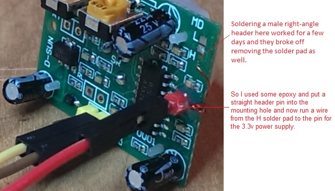
Thanks for the replies, @lininger and @Yveaux. Do you bridge H and the centre solder pad?
Here's my solder effort:
I checked with my multimeter, and soldering a 3.3v wire onto the 7133 leg gets 3.3v to the H solder pad. So I'm pretty sure that I've done the equivalent of yours.
And yet, it doesn't seem to work. After a few seconds my output pin just goes high and never drops low. I've tried to tune the pots but it makes little difference.
Just wanted to check that at least I got the power right. Thanks guys!
-
Moved my solder point to the H pad. Also bridged the H pad with centre pad. All works now. Thanks everyone!
Interesting observation. The motion sketch works very well. But when I try my multisensor sketch it always reads high and keeps triggering. Must be a problem with taking too long in the interrupt. I recall a small discussion about that. Time for some searching...
@Bandra If you configured the interrupt LEVEL triggered (either low or high) you have to wait for the signal to change in the interrupt handler (or e.g. disable the interrupt in the interupt handler) or it will enter the interrupt handler immediately again on exit.
-
@Bandra If you configured the interrupt LEVEL triggered (either low or high) you have to wait for the signal to change in the interrupt handler (or e.g. disable the interrupt in the interupt handler) or it will enter the interrupt handler immediately again on exit.
Thanks @Yveaux
I think I'm pretty safe there because I'm relying on the MySensors library to do the interrupt [ie, the sleep(int, int, long) method]. In that method, the library disables the interrupt itself [in MySensor::sleep it performs a "detachInterrupt(interrupt);" ]I got it going reasonably well by doing two things. I moved the code that tests the D3 pin towards the beginning of the loop(). This helps avoid flapping (ie, if the pin fell low between the time the the interrupt was triggered to the end of the next loop() then it might cause flapping). I also changed my sleep call from:
sleep(INTERRUPT, CHANGE, 30000)to
sleep(INTERRUPT, RISING, 30000)This way, a flapping motion sensor doesn't affect me as much. Those two changes worked a treat. My multisensor sketch works well now!
Thanks again for all your advice on this forum.
-
@bjornhallberg said:
I noticed from the specs that the detection range / cone seems a bit narrow?
I am using them indoors to detect motion in/out of rome and hallways. Seems reliable. I mainly use them in wall outlets to detect legs moving by.
@BulldogLowell said:
I am using them indoors to detect motion in/out of rome and hallways. Seems reliable. I mainly use them in wall outlets to detect legs moving by.
I'd really like to see this. Having the sensor plugged into a wall socket would be perfect! Would you mind sharing how you did this? ie what case etc, so it looks good?
I have searched, but didn't find anything.
thanks
-
-
I want to interface HC-SR501 to my renesas controller..is it possible??????????????they mentioned somewhere for arduino only...thatsy doubt..reply fast
-
Does anybody who has bypassed the onboard regulator on the HC-SR501 be able to post up a photo of where you soldered?
I thought it was pretty simple and soldered my 3.3V lead to the leg on the 7133. It seems to power up (at least, so says my voltmeter), but the trigger (output) pin just goes high immediately and never changes. So on my sensors network it is just constantly triggering (even when there's no motion).
I'm doing something wrong, but not sure what it is. Any hints?
@Bandra said:
Does anybody who has bypassed the onboard regulator on the HC-SR501 be able to post up a photo of where you soldered?
I thought it was pretty simple and soldered my 3.3V lead to the leg on the 7133. It seems to power up (at least, so says my voltmeter), but the trigger (output) pin just goes high immediately and never changes. So on my sensors network it is just constantly triggering (even when there's no motion).
I'm doing something wrong, but not sure what it is. Any hints?
@Bandra , have you found any answers to your question? I have exactly the same problem, the output of the sensor goes straight to High, moving the potentiometers sometimes causes it to go Low but not in a stable state, goes low, you trigger it and goes high and stays this way... Maybe the sensor is on his way out... right now I don't have another one to test with.
-
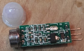
Here is what I did...
Removed the regulator and the diode. Jumpered from the anode of the diode to the location of the output of the 3v3 regulator. Works perfectly, and I can still utilize the original power supply pin! (good for using a standard 3 pin female header, no messy wires). Oh, and make sure your 3v3 power source is clean; boosters are notorious for having significant noise on top of the DC.
-
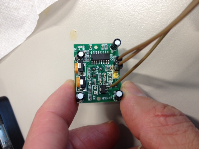
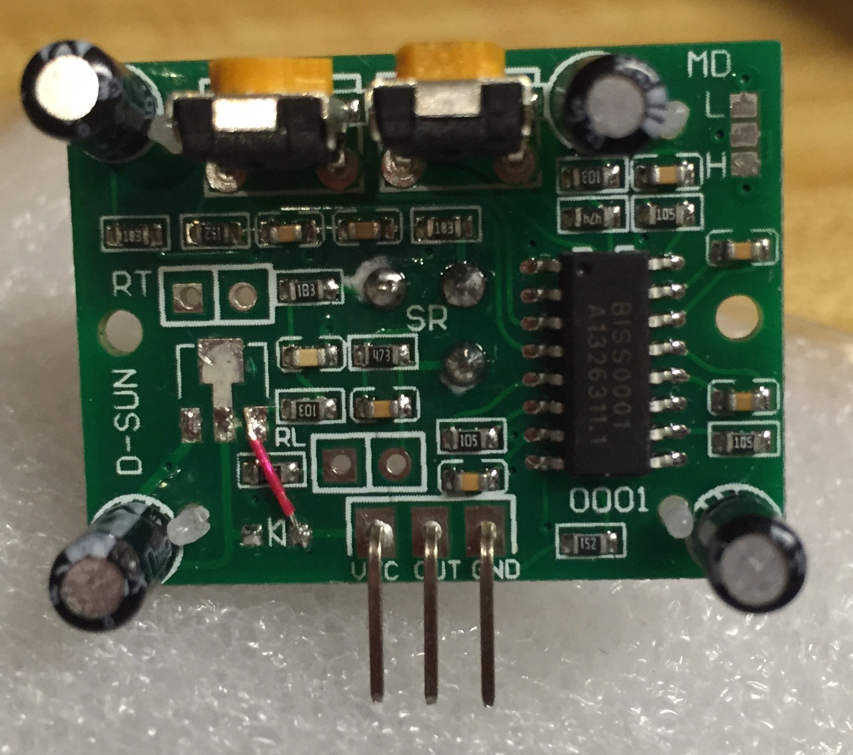
Thank you for your answer. This was not the problem in my case. Long story short, I made a multisensor node for testing on an Arduino Uno and everything went well, the problems started when I moved to Pro Mini 5V version. I only use 3.3V for the radio, all of the other sensors of this node are 5V. The power was not the issue as I used on both Uno and Pro Mini battery power for testing. I moved the sensor back to the Uno setup (used for two weeks for testing) and still was not working. Moved the potentiometer for the Sensibility to the minimum and then I saw random good readings so arrived to the conclusion that there could be some problem with this.
After some searching I found that my Pir had 105 potentiometer both for Sensibility and Time, and in the schematics there is a 104 for Sensibility and 105 for Time, that's why the sensibility worked only the first mm of the rotation. Searched home but unfortunatly the bigest one I had was 10k and not 100k, put it for testing, pump it to the max and is working like a charm. I will try with 100k as soon as I will get some.
![IMG_0659[2].jpg](/uploads/upload-48d8a3dd-4cfe-44c8-a82b-3a785082c4d0.jpg)
This is a picture with the sensor, mine had 105 on both that's why it was so hard to set. Now the multisensor is in a beautifull case, working and looking smart :).