Easy/Newbie PCB for MySensors
-
@Markus. Keep in mind that the RFM69 radio pins are not 5V tolerable so use them only with 3.3V Pro mini. And like you said change the radio type in sketch.
@korttoma yes i use the pro mini 3,3V but can Ireplace the Radios simply with a modification of the Sketch ? Because hen I Flash following Sketch to the Easy pcb:
// Sample RFM69 receiver/gateway sketch, with ACK and optional encryption, and Automatic Transmission Control
// Passes through any wireless received messages to the serial port & responds to ACKs
// It also looks for an onboard FLASH chip, if present
// **********************************************************************************
// Copyright Felix Rusu 2016, http://www.LowPowerLab.com/contact
// **********************************************************************************
// License
// **********************************************************************************
// This program is free software; you can redistribute it
// and/or modify it under the terms of the GNU General
// Public License as published by the Free Software
// Foundation; either version 3 of the License, or
// (at your option) any later version.
//
// This program is distributed in the hope that it will
// be useful, but WITHOUT ANY WARRANTY; without even the
// implied warranty of MERCHANTABILITY or FITNESS FOR A
// PARTICULAR PURPOSE. See the GNU General Public
// License for more details.
//
// Licence can be viewed at
// http://www.gnu.org/licenses/gpl-3.0.txt
//
// Please maintain this license information along with authorship
// and copyright notices in any redistribution of this code
// **********************************************************************************
#include <RFM69.h>         //get it here: https://www.github.com/lowpowerlab/rfm69
#include <RFM69_ATC.h>     //get it here: https://www.github.com/lowpowerlab/rfm69
#include <SPIFlash.h>      //get it here: https://www.github.com/lowpowerlab/spiflash
#include <SPI.h>           //included with Arduino IDE install (www.arduino.cc)

//*********************************************************************************************
//************ IMPORTANT SETTINGS - YOU MUST CHANGE/CONFIGURE TO FIT YOUR HARDWARE *************
//*********************************************************************************************
#define NODEID        1    //unique for each node on same network
#define NETWORKID     100  //the same on all nodes that talk to each other
//Match frequency to the hardware version of the radio on your Moteino (uncomment one):
//#define FREQUENCY     RF69_433MHZ
#define FREQUENCY     RF69_868MHZ
//#define FREQUENCY     RF69_915MHZ
#define ENCRYPTKEY    "sampleEncryptKey" //exactly the same 16 characters/bytes on all nodes!
#define IS_RFM69HW_HCW  //uncomment only for RFM69HW/HCW! Leave out if you have RFM69W/CW!
//*********************************************************************************************
//Auto Transmission Control - dials down transmit power to save battery
//Usually you do not need to always transmit at max output power
//By reducing TX power even a little you save a significant amount of battery power
//This setting enables this gateway to work with remote nodes that have ATC enabled to
//dial their power down to only the required level
#define ENABLE_ATC    //comment out this line to disable AUTO TRANSMISSION CONTROL
//*********************************************************************************************
#define SERIAL_BAUD   115200

#ifdef __AVR_ATmega1284P__
  #define LED           15 // Moteino MEGAs have LEDs on D15
  #define FLASH_SS      23 // and FLASH SS on D23
#else
  #define LED           9 // Moteinos have LEDs on D9
  #define FLASH_SS      8 // and FLASH SS on D8
#endif

#ifdef ENABLE_ATC
  RFM69_ATC radio;
#else
  RFM69 radio;
#endif

SPIFlash flash(FLASH_SS, 0xEF30); //EF30 for 4mbit  Windbond chip (W25X40CL)
bool promiscuousMode = false; //set to 'true' to sniff all packets on the same network

void setup() {
  Serial.begin(SERIAL_BAUD);
  delay(10);
  radio.initialize(FREQUENCY,NODEID,NETWORKID);
#ifdef IS_RFM69HW_HCW
  radio.setHighPower(); //must include this only for RFM69HW/HCW!
#endif
  radio.encrypt(ENCRYPTKEY);
  radio.promiscuous(promiscuousMode);
  //radio.setFrequency(919000000); //set frequency to some custom frequency
  char buff[50];
  sprintf(buff, "\nListening at %d Mhz...", FREQUENCY==RF69_433MHZ ? 433 : FREQUENCY==RF69_868MHZ ? 868 : 915);
  Serial.println(buff);
  if (flash.initialize())
  {
    Serial.print("SPI Flash Init OK. Unique MAC = [");
    flash.readUniqueId();
    for (byte i=0;i<8;i++)
    {
      Serial.print(flash.UNIQUEID[i], HEX);
      if (i!=8) Serial.print(':');
    }
    Serial.println(']');

    //alternative way to read it:
    //byte* MAC = flash.readUniqueId();
    //for (byte i=0;i<8;i++)
    //{
    //  Serial.print(MAC[i], HEX);
    //  Serial.print(' ');
    //}
  }
  else
    Serial.println("SPI Flash MEM not found (is chip soldered?)...");

#ifdef ENABLE_ATC
  Serial.println("RFM69_ATC Enabled (Auto Transmission Control)");
#endif
}

byte ackCount=0;
uint32_t packetCount = 0;
void loop() {
  //process any serial input
  if (Serial.available() > 0)
  {
    char input = Serial.read();
    if (input == 'r') //d=dump all register values
      radio.readAllRegs();
    if (input == 'E') //E=enable encryption
      radio.encrypt(ENCRYPTKEY);
    if (input == 'e') //e=disable encryption
      radio.encrypt(null);
    if (input == 'p')
    {
      promiscuousMode = !promiscuousMode;
      radio.promiscuous(promiscuousMode);
      Serial.print("Promiscuous mode ");Serial.println(promiscuousMode ? "on" : "off");
    }

    if (input == 'd') //d=dump flash area
    {
      Serial.println("Flash content:");
      int counter = 0;

      while(counter<=256){
        Serial.print(flash.readByte(counter++), HEX);
        Serial.print('.');
      }
      while(flash.busy());
      Serial.println();
    }
    if (input == 'D')
    {
      Serial.print("Deleting Flash chip ... ");
      flash.chipErase();
      while(flash.busy());
      Serial.println("DONE");
    }
    if (input == 'i')
    {
      Serial.print("DeviceID: ");
      word jedecid = flash.readDeviceId();
      Serial.println(jedecid, HEX);
    }
    if (input == 't')
    {
      byte temperature =  radio.readTemperature(-1); // -1 = user cal factor, adjust for correct ambient
      byte fTemp = 1.8 * temperature + 32; // 9/5=1.8
      Serial.print( "Radio Temp is ");
      Serial.print(temperature);
      Serial.print("C, ");
      Serial.print(fTemp); //converting to F loses some resolution, obvious when C is on edge between 2 values (ie 26C=78F, 27C=80F)
      Serial.println('F');
    }
  }

  if (radio.receiveDone())
  {
    Serial.print("#[");
    Serial.print(++packetCount);
    Serial.print(']');
    Serial.print('[');Serial.print(radio.SENDERID, DEC);Serial.print("] ");
    if (promiscuousMode)
    {
      Serial.print("to [");Serial.print(radio.TARGETID, DEC);Serial.print("] ");
    }
    for (byte i = 0; i < radio.DATALEN; i++)
      Serial.print((char)radio.DATA[i]);
    Serial.print("   [RX_RSSI:");Serial.print(radio.RSSI);Serial.print("]");

    if (radio.ACKRequested())
    {
      byte theNodeID = radio.SENDERID;
      radio.sendACK();
      Serial.print(" - ACK sent.");

      // When a node requests an ACK, respond to the ACK
      // and also send a packet requesting an ACK (every 3rd one only)
      // This way both TX/RX NODE functions are tested on 1 end at the GATEWAY
      if (ackCount++%3==0)
      {
        Serial.print(" Pinging node ");
        Serial.print(theNodeID);
        Serial.print(" - ACK...");
        delay(3); //need this when sending right after reception .. ?
        if (radio.sendWithRetry(theNodeID, "ACK TEST", 8, 0))  // 0 = only 1 attempt, no retries
          Serial.print("ok!");
        else Serial.print("nothing");
      }
    }
    Serial.println();
    Blink(LED,3);
  }
}

void Blink(byte PIN, int DELAY_MS)
{
  pinMode(PIN, OUTPUT);
  digitalWrite(PIN,HIGH);
  delay(DELAY_MS);
  digitalWrite(PIN,LOW);
}
I get following result:
Listening at 868 Mhz... SPI Flash MEM not found (is chip soldered?)... RFM69_ATC Enabled (Auto Transmission Control) -
Hi All,
I have a lot of these PCBs in Rev.9 running as battery powered sensors. Also some with regulated power. They are running currentl with a NRF24L01. But i need to use on some sensors a RFM69 868 Radio. I have few breakout boards to use a RFM69 on a NRF24L01 connector. Is it possilbe just to replace the Radios on my EasyPBCs NRF to use RFM69 Radios? Think from power perspective should this be working. Well I know I have to Change also the Radio type in the Sketch. But is there anything more to do? Like cabling or specific Settings in the Sketch?Many Thanks
Markus -
I am using these and they work https://www.mysensors.org/hardware/nrf2rfm69
-
No, I only changed the define from nrf24 to rfm69 and that was it. The capacitor I left the one on the EASYPCB near the nrf24 connector (a 10uF ceramic)
-
@sundberg84: Received the V9 boards and started to work with them. Converting my nodes into smaller ones ;-)
I want to use it with my 5v arduino. So need voltage regulator for the radio. I guess you are using LE33 if I read the thread correctly. I have LM1117 which seems to be a hassle to fix on the board with the 'rough bulky' legs. Suggestions or just buy LE33 ;-)
@sincze When I first got my rev8 boards a long time ago I had the same issue. I did manage to bend the leads and solder some extensions on one to get it to work, but in the end it was just too much of a pain in the arse. I ended up buying L78L33ACZ regulators which work just fine, but the board was designed using the LE33. The LE33 is an LDO regulator where the L78L33 is not. The quiscent current of the L78L33 regulator, which is something I forgot to look at when I bought them, is 6mA where the LE33 maxes out at 3mA, which is much better when building battery operated nodes.
-
As mentioned above, it works but you need to watch for the right pins... you might have to be careful bending those pins but I think its managable... My suggestion though is to look for volt. regulators with the same pinout.
-
@sincze When I first got my rev8 boards a long time ago I had the same issue. I did manage to bend the leads and solder some extensions on one to get it to work, but in the end it was just too much of a pain in the arse. I ended up buying L78L33ACZ regulators which work just fine, but the board was designed using the LE33. The LE33 is an LDO regulator where the L78L33 is not. The quiscent current of the L78L33 regulator, which is something I forgot to look at when I bought them, is 6mA where the LE33 maxes out at 3mA, which is much better when building battery operated nodes.
@dbemowsk said in Easy/Newbie PCB for MySensors:
LDO regulator
A well that is a clear answer. So I just ordered a few LE33. The project has to wait.
It still will be a tough one getting everyting attached to the pins. ->. 2x Door Sensor / 3x Dallas DS18B20 / 3x Relais / 2x Control LEDS TX/RX. A well part of the game. Already figured out I have to use the A0x pins as digital ones. As i don't plan to use IRQ I'm really hopeful this nicely designed PCB will offer me A0,A1A4,A5 D2,D3,D5,D6. So should fit ;-) -
@dbemowsk said in Easy/Newbie PCB for MySensors:
LDO regulator
A well that is a clear answer. So I just ordered a few LE33. The project has to wait.
It still will be a tough one getting everyting attached to the pins. ->. 2x Door Sensor / 3x Dallas DS18B20 / 3x Relais / 2x Control LEDS TX/RX. A well part of the game. Already figured out I have to use the A0x pins as digital ones. As i don't plan to use IRQ I'm really hopeful this nicely designed PCB will offer me A0,A1A4,A5 D2,D3,D5,D6. So should fit ;-)@sincze With that much going on, you may want to connect a set of header pins to the outputs next to the nRF24 radio and run that to an external proto-board for connecting all of your devices. You won't make it on the small proto section of the newbie board for everything you want to add.
Vera Plus running UI7 with MySensors, Sonoffs and 1-Wire devices
Visit my website for more Bits, Bytes and Ramblings from me: http://dan.bemowski.info/ -
@sincze With that much going on, you may want to connect a set of header pins to the outputs next to the nRF24 radio and run that to an external proto-board for connecting all of your devices. You won't make it on the small proto section of the newbie board for everything you want to add.
@dbemowsk @sincze - its a good idea with a proto board or you can build something and add as an shield on the MysX connector... I would also suggest you run a seperate power regulator for the sensors... atleast do some calculactions before adding them in because LE33 can handle maximum of 0.2A i think.
Controller: Proxmox VM - Home Assistant
MySensors GW: Arduino Uno - W5100 Ethernet, Gw Shield Nrf24l01+ 2,4Ghz
MySensors GW: Arduino Uno - Gw Shield RFM69, 433mhz
RFLink GW - Arduino Mega + RFLink Shield, 433mhz -
@dbemowsk @sincze - its a good idea with a proto board or you can build something and add as an shield on the MysX connector... I would also suggest you run a seperate power regulator for the sensors... atleast do some calculactions before adding them in because LE33 can handle maximum of 0.2A i think.
@sundberg84 Ok tnx for the heads up. Currently I have everything in DEMO up and running on a NANO on my desk (using the exact same pins as I would on your PCB.
I was thinking of the following. Power the PCB with 5v and use a 5v arduino mini, use the LE33 to power the Antenna with 3,3v. Hopefully this will enable the pins Mys pins A0 ...Dx with 5v.(Have to look at the schematic to be sure). Keeping your advise in mind to add some extra juice I have to power the RELAIS & Temp sensor separately with 5v and keep the grounds of everything together with the PCB. I think it should work. But maybe I am missing something. -
@sundberg84 Ok tnx for the heads up. Currently I have everything in DEMO up and running on a NANO on my desk (using the exact same pins as I would on your PCB.
I was thinking of the following. Power the PCB with 5v and use a 5v arduino mini, use the LE33 to power the Antenna with 3,3v. Hopefully this will enable the pins Mys pins A0 ...Dx with 5v.(Have to look at the schematic to be sure). Keeping your advise in mind to add some extra juice I have to power the RELAIS & Temp sensor separately with 5v and keep the grounds of everything together with the PCB. I think it should work. But maybe I am missing something.@sincze all you can do is test and learn !!
-
@dbemowsk @sincze - its a good idea with a proto board or you can build something and add as an shield on the MysX connector... I would also suggest you run a seperate power regulator for the sensors... atleast do some calculactions before adding them in because LE33 can handle maximum of 0.2A i think.
@sundberg84 Couldn't think of the name of the MysX connector when I did that post, but that's what I was talking about putting the header on to connect to the proto-board. Mainly to act as a proto-shield. I would agree to run the sensors from a separate regulator. If he plugs it into the MysX connector he should have access to RAW power if he jumpers the pads next to the MysX connector, and then he may be able to make use of at least one of his LM1117 regulators on his shield, provided that he runs the sensors from 3.3V. I am assuming that his LM1117's are 3.3V regulators and not the 5V versions.
Vera Plus running UI7 with MySensors, Sonoffs and 1-Wire devices
Visit my website for more Bits, Bytes and Ramblings from me: http://dan.bemowski.info/ -
@sundberg84 Couldn't think of the name of the MysX connector when I did that post, but that's what I was talking about putting the header on to connect to the proto-board. Mainly to act as a proto-shield. I would agree to run the sensors from a separate regulator. If he plugs it into the MysX connector he should have access to RAW power if he jumpers the pads next to the MysX connector, and then he may be able to make use of at least one of his LM1117 regulators on his shield, provided that he runs the sensors from 3.3V. I am assuming that his LM1117's are 3.3V regulators and not the 5V versions.
@dbemowsk Got in stock 2 types of LM1117 the 3,3v and 5v. In any case the relais need 5v, the temp sensor as well. So If I read RAW in your answer that triggers me to watch out. ;-) I'll start soldering some pins and measure the voltage. as @sundberg84 said.. "all you can do is test and learn !! hehehe. Part of the Mysensors fun. And ofcourse this forum provides me with experienced feedback.
-
@dbemowsk Got in stock 2 types of LM1117 the 3,3v and 5v. In any case the relais need 5v, the temp sensor as well. So If I read RAW in your answer that triggers me to watch out. ;-) I'll start soldering some pins and measure the voltage. as @sundberg84 said.. "all you can do is test and learn !! hehehe. Part of the Mysensors fun. And ofcourse this forum provides me with experienced feedback.
So this is where the project is at. Using regulated 5V.
Still missing the 0,1u capacitor, but it is on its way,
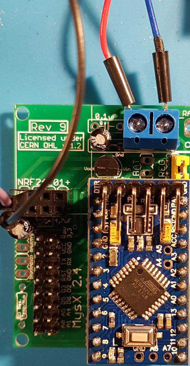
The voltage divider is working fine 5v -> 3,3v.
Maybe I am missing some(connection)thing as I don't have 3,3v at the Antenna 3,3/GND connector. Did I miss something as I am not a PCB expert, sorry. -
So this is where the project is at. Using regulated 5V.
Still missing the 0,1u capacitor, but it is on its way,
The voltage divider is working fine 5v -> 3,3v.
Maybe I am missing some(connection)thing as I don't have 3,3v at the Antenna 3,3/GND connector. Did I miss something as I am not a PCB expert, sorry.I don't have 3,3v at the Antenna 3,3/GND connector
If you measure these points, what do you have?
- plus (left pin) on blue screw terminal (should be 5v)
- reg jumper (should be 5v)
- Vin voltage reg (should be 5v)
- Vout Voltage reg (should be 3.3v)
You should be able to follow the trace from Vout to VCC(radio) with your eye.
You can do a continuity test from Vout to VCC (radio) and GND(radio) to GND(screw terminal) to comfirm connectiom.What kind of voltage regulator do you have? Did you check the pinout matched vin/vout/gnd ?
Still missing the 0,1u capacitor, but it is on its way,
No rush, this supports the voltage reg but unless you do some heavy things you will do without.
Controller: Proxmox VM - Home Assistant
MySensors GW: Arduino Uno - W5100 Ethernet, Gw Shield Nrf24l01+ 2,4Ghz
MySensors GW: Arduino Uno - Gw Shield RFM69, 433mhz
RFLink GW - Arduino Mega + RFLink Shield, 433mhz -
I don't have 3,3v at the Antenna 3,3/GND connector
If you measure these points, what do you have?
- plus (left pin) on blue screw terminal (should be 5v)
- reg jumper (should be 5v)
- Vin voltage reg (should be 5v)
- Vout Voltage reg (should be 3.3v)
You should be able to follow the trace from Vout to VCC(radio) with your eye.
You can do a continuity test from Vout to VCC (radio) and GND(radio) to GND(screw terminal) to comfirm connectiom.What kind of voltage regulator do you have? Did you check the pinout matched vin/vout/gnd ?
Still missing the 0,1u capacitor, but it is on its way,
No rush, this supports the voltage reg but unless you do some heavy things you will do without.
@sundberg84 I did measure the following:
plus (left pin) on blue screw terminal (should be 5v), is 4,96 V
Vin voltage reg (should be 5v), is 4,96
Vout Voltage reg (should be 3.3v), is 3,3