Easy/Newbie PCB for MySensors
-
@sincze With that much going on, you may want to connect a set of header pins to the outputs next to the nRF24 radio and run that to an external proto-board for connecting all of your devices. You won't make it on the small proto section of the newbie board for everything you want to add.
@dbemowsk @sincze - its a good idea with a proto board or you can build something and add as an shield on the MysX connector... I would also suggest you run a seperate power regulator for the sensors... atleast do some calculactions before adding them in because LE33 can handle maximum of 0.2A i think.
Controller: Proxmox VM - Home Assistant
MySensors GW: Arduino Uno - W5100 Ethernet, Gw Shield Nrf24l01+ 2,4Ghz
MySensors GW: Arduino Uno - Gw Shield RFM69, 433mhz
RFLink GW - Arduino Mega + RFLink Shield, 433mhz -
@dbemowsk @sincze - its a good idea with a proto board or you can build something and add as an shield on the MysX connector... I would also suggest you run a seperate power regulator for the sensors... atleast do some calculactions before adding them in because LE33 can handle maximum of 0.2A i think.
@sundberg84 Ok tnx for the heads up. Currently I have everything in DEMO up and running on a NANO on my desk (using the exact same pins as I would on your PCB.
I was thinking of the following. Power the PCB with 5v and use a 5v arduino mini, use the LE33 to power the Antenna with 3,3v. Hopefully this will enable the pins Mys pins A0 ...Dx with 5v.(Have to look at the schematic to be sure). Keeping your advise in mind to add some extra juice I have to power the RELAIS & Temp sensor separately with 5v and keep the grounds of everything together with the PCB. I think it should work. But maybe I am missing something. -
@sundberg84 Ok tnx for the heads up. Currently I have everything in DEMO up and running on a NANO on my desk (using the exact same pins as I would on your PCB.
I was thinking of the following. Power the PCB with 5v and use a 5v arduino mini, use the LE33 to power the Antenna with 3,3v. Hopefully this will enable the pins Mys pins A0 ...Dx with 5v.(Have to look at the schematic to be sure). Keeping your advise in mind to add some extra juice I have to power the RELAIS & Temp sensor separately with 5v and keep the grounds of everything together with the PCB. I think it should work. But maybe I am missing something.@sincze all you can do is test and learn !!
-
@dbemowsk @sincze - its a good idea with a proto board or you can build something and add as an shield on the MysX connector... I would also suggest you run a seperate power regulator for the sensors... atleast do some calculactions before adding them in because LE33 can handle maximum of 0.2A i think.
@sundberg84 Couldn't think of the name of the MysX connector when I did that post, but that's what I was talking about putting the header on to connect to the proto-board. Mainly to act as a proto-shield. I would agree to run the sensors from a separate regulator. If he plugs it into the MysX connector he should have access to RAW power if he jumpers the pads next to the MysX connector, and then he may be able to make use of at least one of his LM1117 regulators on his shield, provided that he runs the sensors from 3.3V. I am assuming that his LM1117's are 3.3V regulators and not the 5V versions.
Vera Plus running UI7 with MySensors, Sonoffs and 1-Wire devices
Visit my website for more Bits, Bytes and Ramblings from me: http://dan.bemowski.info/ -
@sundberg84 Couldn't think of the name of the MysX connector when I did that post, but that's what I was talking about putting the header on to connect to the proto-board. Mainly to act as a proto-shield. I would agree to run the sensors from a separate regulator. If he plugs it into the MysX connector he should have access to RAW power if he jumpers the pads next to the MysX connector, and then he may be able to make use of at least one of his LM1117 regulators on his shield, provided that he runs the sensors from 3.3V. I am assuming that his LM1117's are 3.3V regulators and not the 5V versions.
@dbemowsk Got in stock 2 types of LM1117 the 3,3v and 5v. In any case the relais need 5v, the temp sensor as well. So If I read RAW in your answer that triggers me to watch out. ;-) I'll start soldering some pins and measure the voltage. as @sundberg84 said.. "all you can do is test and learn !! hehehe. Part of the Mysensors fun. And ofcourse this forum provides me with experienced feedback.
-
@dbemowsk Got in stock 2 types of LM1117 the 3,3v and 5v. In any case the relais need 5v, the temp sensor as well. So If I read RAW in your answer that triggers me to watch out. ;-) I'll start soldering some pins and measure the voltage. as @sundberg84 said.. "all you can do is test and learn !! hehehe. Part of the Mysensors fun. And ofcourse this forum provides me with experienced feedback.
So this is where the project is at. Using regulated 5V.
Still missing the 0,1u capacitor, but it is on its way,
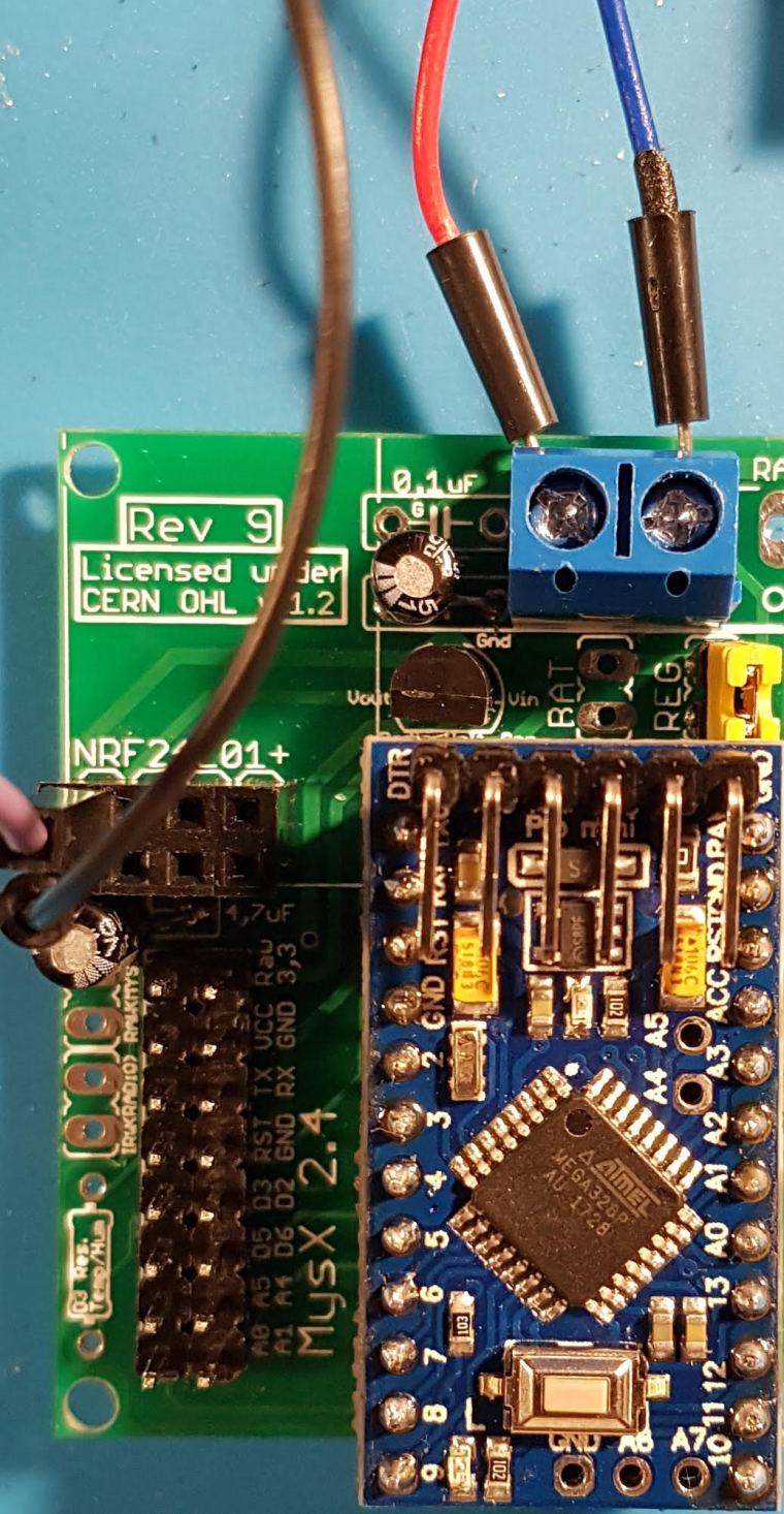
The voltage divider is working fine 5v -> 3,3v.
Maybe I am missing some(connection)thing as I don't have 3,3v at the Antenna 3,3/GND connector. Did I miss something as I am not a PCB expert, sorry. -
So this is where the project is at. Using regulated 5V.
Still missing the 0,1u capacitor, but it is on its way,
The voltage divider is working fine 5v -> 3,3v.
Maybe I am missing some(connection)thing as I don't have 3,3v at the Antenna 3,3/GND connector. Did I miss something as I am not a PCB expert, sorry.I don't have 3,3v at the Antenna 3,3/GND connector
If you measure these points, what do you have?
- plus (left pin) on blue screw terminal (should be 5v)
- reg jumper (should be 5v)
- Vin voltage reg (should be 5v)
- Vout Voltage reg (should be 3.3v)
You should be able to follow the trace from Vout to VCC(radio) with your eye.
You can do a continuity test from Vout to VCC (radio) and GND(radio) to GND(screw terminal) to comfirm connectiom.What kind of voltage regulator do you have? Did you check the pinout matched vin/vout/gnd ?
Still missing the 0,1u capacitor, but it is on its way,
No rush, this supports the voltage reg but unless you do some heavy things you will do without.
Controller: Proxmox VM - Home Assistant
MySensors GW: Arduino Uno - W5100 Ethernet, Gw Shield Nrf24l01+ 2,4Ghz
MySensors GW: Arduino Uno - Gw Shield RFM69, 433mhz
RFLink GW - Arduino Mega + RFLink Shield, 433mhz -
I don't have 3,3v at the Antenna 3,3/GND connector
If you measure these points, what do you have?
- plus (left pin) on blue screw terminal (should be 5v)
- reg jumper (should be 5v)
- Vin voltage reg (should be 5v)
- Vout Voltage reg (should be 3.3v)
You should be able to follow the trace from Vout to VCC(radio) with your eye.
You can do a continuity test from Vout to VCC (radio) and GND(radio) to GND(screw terminal) to comfirm connectiom.What kind of voltage regulator do you have? Did you check the pinout matched vin/vout/gnd ?
Still missing the 0,1u capacitor, but it is on its way,
No rush, this supports the voltage reg but unless you do some heavy things you will do without.
@sundberg84 I did measure the following:
plus (left pin) on blue screw terminal (should be 5v), is 4,96 V
Vin voltage reg (should be 5v), is 4,96
Vout Voltage reg (should be 3.3v), is 3,3 -
@sundberg84 I did measure the following:
plus (left pin) on blue screw terminal (should be 5v), is 4,96 V
Vin voltage reg (should be 5v), is 4,96
Vout Voltage reg (should be 3.3v), is 3,3@sincze but still 0v at radio VCC?
Controller: Proxmox VM - Home Assistant
MySensors GW: Arduino Uno - W5100 Ethernet, Gw Shield Nrf24l01+ 2,4Ghz
MySensors GW: Arduino Uno - Gw Shield RFM69, 433mhz
RFLink GW - Arduino Mega + RFLink Shield, 433mhz -
@sincze but still 0v at radio VCC?
@sundberg84 unfortunately yes. However.
You can do a continuity test from Vout to VCC (radio) , (We have no beep for continuity)
and
GND(radio) to GND(screw terminal) to comfirm connectiom. (We have a beep for contiuity) -
@sundberg84 unfortunately yes. However.
You can do a continuity test from Vout to VCC (radio) , (We have no beep for continuity)
and
GND(radio) to GND(screw terminal) to comfirm connectiom. (We have a beep for contiuity)@sincze if this is so you have a broken pcb trace (first time I ever heard of) do you need to replace the trace with a wire.
-
@sundberg84 unfortunately yes. However.
You can do a continuity test from Vout to VCC (radio) , (We have no beep for continuity)
and
GND(radio) to GND(screw terminal) to comfirm connectiom. (We have a beep for contiuity)@sincze or a bad solder joint...
Controller: Proxmox VM - Home Assistant
MySensors GW: Arduino Uno - W5100 Ethernet, Gw Shield Nrf24l01+ 2,4Ghz
MySensors GW: Arduino Uno - Gw Shield RFM69, 433mhz
RFLink GW - Arduino Mega + RFLink Shield, 433mhz -
@sincze or a bad solder joint...
@sundberg84 as I am not a soldering king... we will check the work and report back...... applied a bit more solder to the vout and we have beep ;-) now let's continue the work.
Wow, 3,3 and 3,29v on the antenna. tnx. -
@sundberg84 as I am not a soldering king... we will check the work and report back...... applied a bit more solder to the vout and we have beep ;-) now let's continue the work.
Wow, 3,3 and 3,29v on the antenna. tnx.@sincze no worries. Good luck.
-
Hi,
I‘m new to MySensors and the Newbie PCB. At the weekend I build my first sensor but I had one Problem. I want to use battery powered sensors so I’m using the 3.3V battery booster. I’m have connected/soltered everything and the Arduino was runing fine. But the NRF24-Module wasn’t working. I cheked it and there was no voltage at the Vcc pin of the NRF24. Then I found out, the NRF24 is only powered if the battery jumper is closed. If the battery jumper is opened there is not voltage at the NRF24 module and also not at the 3.3 pin of the MysX pin out. Ist this correct?I thought the NRF24 is powered by the battery booster by default. Or did I get it wrong? -
@sincze no worries. Good luck.
@sundberg84 tnx.
I looked at the FAQ and could not find an explaination how to use the pins TX/RX.The following is now on my build list, but maybe if I can use TX/RX pins it will free something...
- LED RX=A05
- LED TX=D02
- Relay_1=A00
- Relay_2=A01
- Relay_3=A04
- Temp_D03 (total of 4, resistor currently already soldered into the wire)
- Door_Switch=D05
- Leakage_Switch=D06
I tested the sketch on a Arduino Nano and it is working, now I need to convert everything to the Easy/Newbie PCB. ;-)
-
@SolderNewbie of course you need to close that jumper since you are using batteries.
@gohan
But i want to power the NRF24 with the battery booster and not directly with the batteries. Is this possible? The NRF24 modules is working with 1.9V than i have to replace the batteries. But with the battery booster i can drain the batteries down to 0.4 V each! -
I think I did once a little mod for that case: I shorted Vin and Vout where the radio voltage regulator would be.
PS but I shorted REG and not BAT
@gohan Thanks for this hint!
I put a jumper into Vo and Vi of the voltage regulator pins and shorten it, that's all! Not needed to shorten REG or BAT jumper! The Vi pin is connected to the Vo of the battery booster and the Vo of the voltage regulator pin is connected to Vcc of the NRF24 module.Maybe an idea for rev 10? Battery booster powered NRF24 module?