In wall - PCB, (AC to DC 5v)
-
@mzuidwijk : The HLK library for eagles: HKLPM01.rar
@m26872 : Since the ciriut works it conducts, i have not tested at which point it breaks because i dont have that equipment :( would be great if we somehow could estabilsh the right compont to use.@sundberg84 Of course it conducts, probably bidirectional too since it works well for you. That's why I suggested a TVS diode. The test was meant as an easy way to find more info even if it does not fully rule out that it still could be something else than a normal fuse. I'm sure you have possibility to test if something conducts or not at low voltages. If it does not, it is not a fuse. Use a new component since it could be a "fail-short" type one.
Then if you connect it in series to a load (> 230V*0.2A "=" 46W), it should blow if it's a fuse.That first fuse is the no1 safety component and should be trusted. I would never just rely an some 10A house fuse to a diy design like this. Removing the varistor could limit the failure modes in the meantime.
-
@m26872 Ok, you seem to know more about this - i have pretty much tried to sum up what was told in the safe-in-wall thread.
Do you agree with that thread or would you do it some other way ? (High power parts and HKL PM01).Controller: Proxmox VM - Home Assistant
MySensors GW: Arduino Uno - W5100 Ethernet, Gw Shield Nrf24l01+ 2,4Ghz
MySensors GW: Arduino Uno - Gw Shield RFM69, 433mhz
RFLink GW - Arduino Mega + RFLink Shield, 433mhz -
@m26872 Ok, you seem to know more about this - i have pretty much tried to sum up what was told in the safe-in-wall thread.
Do you agree with that thread or would you do it some other way ? (High power parts and HKL PM01).@sundberg84 I think the conclusions of that thread is just fine. Now here, it's just a matter of a single component. If you feel safe as it is, ok by me.
I've done quite a few diy's over the years and that fuse has been my insurance. And saved me, more than once...
Edit: That last sentence sounded a bit bumptious, sorry. I now understand that you probably meant what I said about removing the varistor. There I meant that the varistor is after the fuse because of its hazards. If there is no fuse, it could be better to remove the varistor or at least place it after the thermal fuse.
-
@m26872 I really appreiacte your posts! I never feel safe enough! Would it be safer to have the varistor after the thermal fuse as well? Then the thermal fuse breaks both if the varistor gets hot from over voltage and also protect the HLK.
I will try to test my fuses as well - its a good thought. - You never know what you get from Ebay!
Edit: The "fuse" conducts low voltages (1.3V) connected to a normal battery and my Multimeter - so this excludes that it is a TVS diode?
Will later find some eqipment drawing more than 45W and see if that blows it :) Love to blow stuff... :collision:Controller: Proxmox VM - Home Assistant
MySensors GW: Arduino Uno - W5100 Ethernet, Gw Shield Nrf24l01+ 2,4Ghz
MySensors GW: Arduino Uno - Gw Shield RFM69, 433mhz
RFLink GW - Arduino Mega + RFLink Shield, 433mhz -
@m26872 I really appreiacte your posts! I never feel safe enough! Would it be safer to have the varistor after the thermal fuse as well? Then the thermal fuse breaks both if the varistor gets hot from over voltage and also protect the HLK.
I will try to test my fuses as well - its a good thought. - You never know what you get from Ebay!
Edit: The "fuse" conducts low voltages (1.3V) connected to a normal battery and my Multimeter - so this excludes that it is a TVS diode?
Will later find some eqipment drawing more than 45W and see if that blows it :) Love to blow stuff... :collision:@sundberg84 Yes, that fuses-varistor arrangement is like how I do it.
Great that it conducts, I hope in both directions or else it's a diode.
-
@m26872 It conducts both ways, and there is some voltage depending resistance because the volage drops and its different depending which way i put gnd.
Also, it does not blow :( so its not a fuse.
At the end i connected my vaccumcleaner (1000w) and it didnt blow, all it did was vaccum really slow so i guess its some sort of bidirectional TVS. Good find, thank you!I will keep looking for a 250v 200mA fuse (small) one - you dont happen to know one?
-
Also, i tested the thermal fuse and that one killed/blew! Couldnt measure the exakt temp because all i had was my barbecue thermometer atm and i fired to much to fast... but it blew pretty much were it was supposed to.,
-
@m26872 It conducts both ways, and there is some voltage depending resistance because the volage drops and its different depending which way i put gnd.
Also, it does not blow :( so its not a fuse.
At the end i connected my vaccumcleaner (1000w) and it didnt blow, all it did was vaccum really slow so i guess its some sort of bidirectional TVS. Good find, thank you!I will keep looking for a 250v 200mA fuse (small) one - you dont happen to know one?
@sundberg84 said:
@m26872 It conducts both ways, and there is some voltage depending resistance because the volage drops and its different depending which way i put gnd.
Maybe a zener diode? Can you read some figures on it?
Also, it does not blow :( so its not a fuse.
:thumbsup: Good job with the testing!
You're welcome.
I will keep looking for a 250v 200mA fuse (small) one - you dont happen to know one?
This far I've only used standard replacable 5x20mm glass fuses and holders (preferably covered). These are safe and proven but quite bulky and hence not as convienient for our PCB designs. I've ordered a few small ones with solderlegs for testing but not yet recieved them.
-
New revision ordered:

and also some new fuses:
http://www.ebay.com/itm/290767404446?_trksid=p2057872.m2749.l2649&ssPageName=STRK%3AMEBIDX%3AIT
http://www.ebay.com/itm/231765976267?_trksid=p2057872.m2749.l2649&ssPageName=STRK%3AMEBIDX%3AITOf of them is 500mA but that cant matter that much?
Spec of HKL:
Maximum input current ≤0.2 A
Input current surge ; ≤10 A -
@sundberg84 Would you mind posting pictures of your fuses that turned out not to be fuses? I think a few of us ordered from the same store and I'd like to update my original post with a warning. Also, if you don't mind can you post a step by step way for to easily test? If there is another way besides connecting to my vacuum cleaner that would be awesome :)
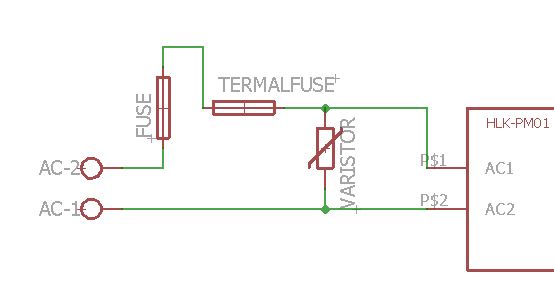
@m26872 & @sundberg84 can you describe in a little more detail the change of placement of the Varistor? I don't really understand why it's better to change the placement. I'd like to update my first post in this thread with the best/safest method http://forum.mysensors.org/topic/1607/safe-in-wall-ac-to-dc-transformers
Thanks!
My "How To" home automation video channel: https://www.youtube.com/channel/UCq_Evyh5PQALx4m4CQuxqkA
-
@sundberg84 Would you mind posting pictures of your fuses that turned out not to be fuses? I think a few of us ordered from the same store and I'd like to update my original post with a warning. Also, if you don't mind can you post a step by step way for to easily test? If there is another way besides connecting to my vacuum cleaner that would be awesome :)
@m26872 & @sundberg84 can you describe in a little more detail the change of placement of the Varistor? I don't really understand why it's better to change the placement. I'd like to update my first post in this thread with the best/safest method http://forum.mysensors.org/topic/1607/safe-in-wall-ac-to-dc-transformers
Thanks!
-
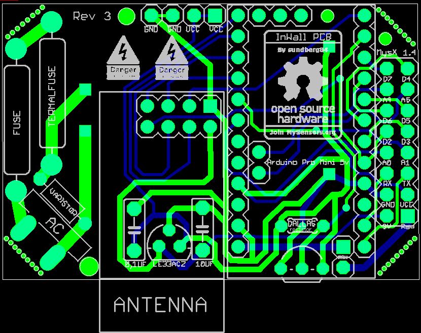
I now have my boards in transit on their way to me as we speak @sundberg84, the next revision will see some development towards some AC/DC conversion i think. However i have a lot of work to do, a lot of learning electronics before i go anywhere near to installing a AC/DC converted board into my wall. Safety first and all that jazz! I love the look of your board layout with the arduino being a add-on board essentially. So as soon as i have my battery version up, working and dialed in for performance, i will be using your board as a learning curve for some AC/DC powering. I actually have printed the above picture of your board out and i'm creating a schematic of it, using it to learn the steps you have taken to get your power to the arduino. I love the fact you have added a temp sensor in there, i'm not too sure why you did that (your personal requirements) but i would love to use this as another trip out sensor to cut the board's power if it detects it getting too hot inside of the socket.
By creating my own i'm not trying to better or improve yours, its simply because for mine to work i would like it to be acceptable into a 29mm depth back box (29mm is with the switch back too, its pretty cramped inside these).
Lastly, is there any chance you could point me in the direction to a copy of your logo/design on the board (The open source, join MySensors.org) so i could include it into mine. I would also like to have the MySensors' official logo on my finished board too, do you know if there is any links/pages/repos to this data or would i just need to create my own as a BMP or Library device?
-
The test I did was just to strip a extension cord, attach "the fuse" to it and apply different equipment with spec from 5W up to my vaccumcl 1000+W Not proffessional but I dont have any other equipment.
I dont think we changed the placement? I made a misstake in my first rev but now my varistor placement is like your post (after both fuse and termal fuse). But @m26872 link describes it good why.
@samuel235 Good luck with your board! Do not take my board as "thats how it should be". My board is the result and my interpretation of the discussions so far in this forum. If that is right or wrong i not able to tell (yet). The tempsensor is to initially be able to measure the temp in that closed box to see that the node doesnt produce to much heat.
Im glad you are creating your own... as i said before, my wish is that we all come together and in the end create a small and safe in wall PCB. And If you want (and use Eagles) ill send over the files for the PCB. I will also post them here when i recieved the boards offcourse.
Here is my bitmap I use as a logo... in eagles you can import that to layer 21 and apply to your board.

Controller: Proxmox VM - Home Assistant
MySensors GW: Arduino Uno - W5100 Ethernet, Gw Shield Nrf24l01+ 2,4Ghz
MySensors GW: Arduino Uno - Gw Shield RFM69, 433mhz
RFLink GW - Arduino Mega + RFLink Shield, 433mhz -
The test I did was just to strip a extension cord, attach "the fuse" to it and apply different equipment with spec from 5W up to my vaccumcl 1000+W Not proffessional but I dont have any other equipment.
I dont think we changed the placement? I made a misstake in my first rev but now my varistor placement is like your post (after both fuse and termal fuse). But @m26872 link describes it good why.
@samuel235 Good luck with your board! Do not take my board as "thats how it should be". My board is the result and my interpretation of the discussions so far in this forum. If that is right or wrong i not able to tell (yet). The tempsensor is to initially be able to measure the temp in that closed box to see that the node doesnt produce to much heat.
Im glad you are creating your own... as i said before, my wish is that we all come together and in the end create a small and safe in wall PCB. And If you want (and use Eagles) ill send over the files for the PCB. I will also post them here when i recieved the boards offcourse.
Here is my bitmap I use as a logo... in eagles you can import that to layer 21 and apply to your board.
Awesome, yes if you could send me the eagle files I would really appreciate that to allow me to learn how this circuit is working. I completely understand that this is just your interpritation on how it should work. I'm using this as a kind of reference i suppose, just to learn how this is wired out, whats connected in what order etc etc. I will not take this as a 'only way to get ac power to arduino on one board' type of application, don't worry ;)
Thank you for the BMP Image, i will add the MySensors logo to the board too along side of this logo.
The parts for my board have just arrived as I was replying to this. Just waiting on the boards to come from ITead now. Time to get moving!
I have a weird feeling that 2016 will be huge for MySensors and its community!
-
@sundberg84 Thanks for the picture. It's totally different than mine. You said you got it from the same store I linked to in the "Safe in-wall" post? This is what mine looks like:
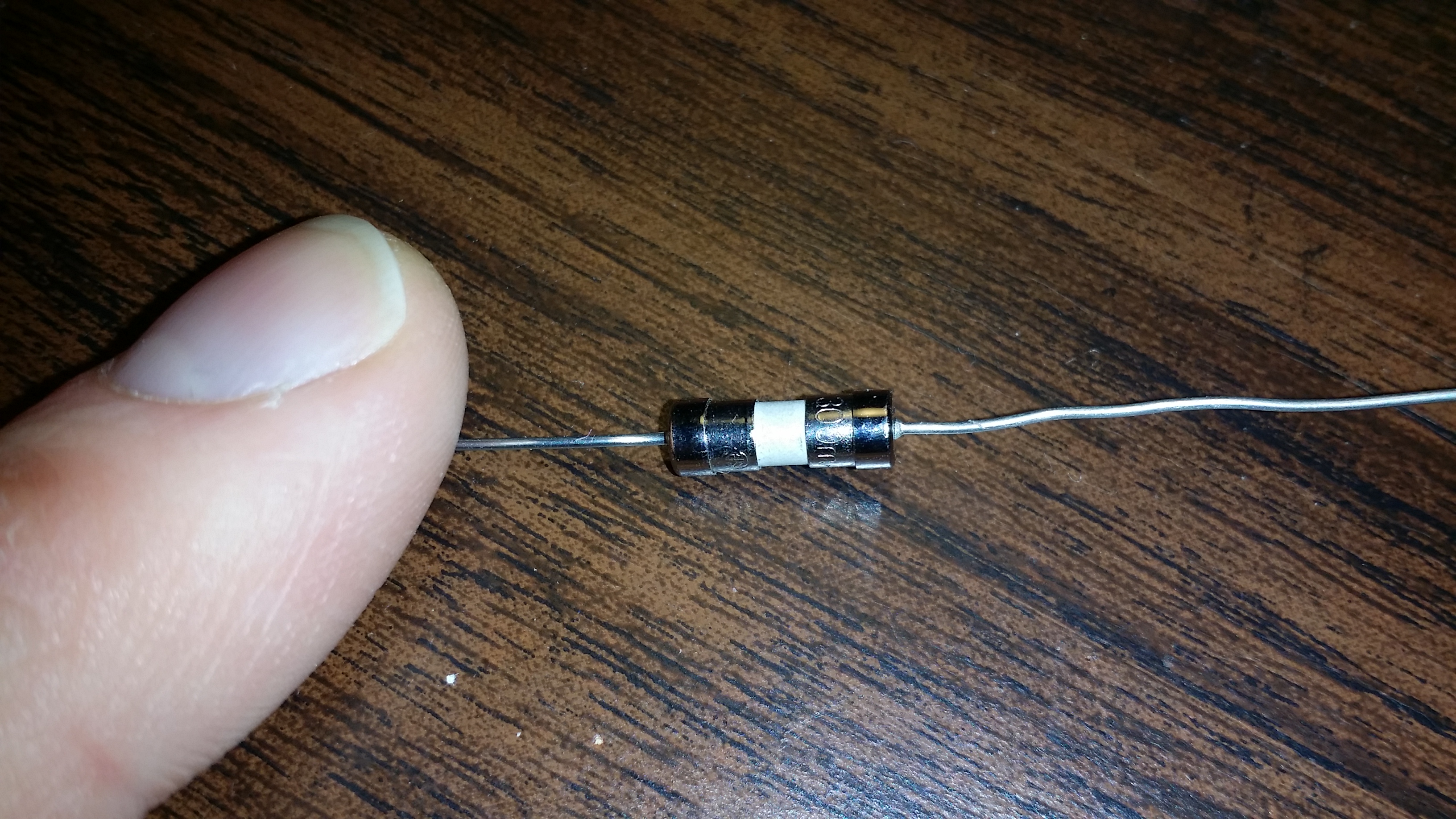
I will still test it with to be sure but I'm reassured that it at least looks different.
I dont think we changed the placement?
Sorry, you're right, my mistake. I misread/misunderstood the issue as I was reading through this thread. It was still helpful to read @m26872's link though, thanks for that!
-
The test I did was just to strip a extension cord, attach "the fuse" to it and apply different equipment with spec from 5W up to my vaccumcl 1000+W Not proffessional but I dont have any other equipment.
I dont think we changed the placement? I made a misstake in my first rev but now my varistor placement is like your post (after both fuse and termal fuse). But @m26872 link describes it good why.
@samuel235 Good luck with your board! Do not take my board as "thats how it should be". My board is the result and my interpretation of the discussions so far in this forum. If that is right or wrong i not able to tell (yet). The tempsensor is to initially be able to measure the temp in that closed box to see that the node doesnt produce to much heat.
Im glad you are creating your own... as i said before, my wish is that we all come together and in the end create a small and safe in wall PCB. And If you want (and use Eagles) ill send over the files for the PCB. I will also post them here when i recieved the boards offcourse.
Here is my bitmap I use as a logo... in eagles you can import that to layer 21 and apply to your board.
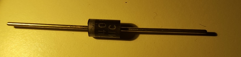
@sundberg84 Your 'fuse' looks very much like a regular diode, e.g. 1N4007:
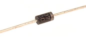
You can easily verify by using a multimeter, or even the printing on the component could reveal its real identity.
Some sellers ship both clothes and electronic components, so maybe the seller just shipped the wrong parts? -
@Yveaux Yea, could be - its not a 1n4007 because i have those as well, and also it conducts in two ways. Anyway, you are probably right - they shipped the wrong item. @petewill I ordered from the link in safe-in-wall thread: http://www.ebay.com/itm/111433875797?_trksid=p2057872.m2749.l2649&ssPageName=STRK%3AMEBIDX%3AIT&rmvSB=true
-
I finally had a spare minute to test my fuse. Good news, it worked! I plugged in a 13 watt florescent light bulb and it turned on. I then plugged in a 32 Watt florescent light bulb and it blew the fuse. @sundberg84 sorry you got the wrong ones! Hopefully other people who ordered got the ones that I did.
-
This post is archived!
Please use this thread to post questions:https://forum.mysensors.org/topic/2783/in-wall-ac-dc-pcb-for-mysensors
Project can be found here:
https://www.openhardware.io/view/13/In-Wall-ACDC-Pcb-for-MySensors
Hi!
As i mentioned in another post i had this idea to stack two PCB on top of each other to fit inside a wall appliance box. This idea has evolved (see below).
Im aware of the big security risk here, and have tried to read:
- http://forum.mysensors.org/topic/1607/safe-in-wall-ac-to-dc-transformers
- http://forum.mysensors.org/topic/1540/110v-230v-ac-to-mysensors-pcb-board
EDIT 03/1/2016
After discussion on this here are the findings of this thread (as of now):I will update this post with BOM and eagles files as soon as i get a node running.
...............................
BOM/README: http://1drv.ms/1kCzue5
GERBER: InWallMySensor3.0.rar
EAGLES: InWallMySensor3.0Eagles.rar
Build images: http://1drv.ms/1lsleox
...............................If you are using this design, please know about the risks when you work with high power. This design has no guarantee s so use it on your own risk!
@sundberg84, gr8 job done....really amazing to see this one. i want to make few sensors for my home. Is the design of the board is final? Kindly guide me for the placement of LE33 and Dallas Temp as mentioned in your BOM that placement "solder Le33 + Caps (1,0, 10uf) on the pcb underside. Note the directions of the LE33 (not as silk mask!)"
Also, will it be possible for you to upload the design to http://dirtypcbs.com, as i don't have any knowledge about PCB manufacturing. it will be very easy for me to order and get the PCBs for assembly.
I am very new to all this and learning from you guys.....
Thanks
Brijesh -
@Brijesh-Mishra Thank you! Im waiting for Rev3 to arrive. It was manufactured a week ago so i guess it will arrive on 1-2 weeks. I will post and let you know the status here.
I will also update the BOM with better instructions. LE33 should be soldered on the back side which reverse the direction of the pins (VCC/OUT). This means that the nice print on silkmask (white markings how the LE33 should be mounted) is not correct.
Its a nice idea at dirtypcb, I can do that i guess!