3 in 1 incl battery monitor
-
@ericvdb http://www.microchip.com/stellent/idcplg?IdcService=SS_GET_PAGE&nodeId=2680&dDocName=en545243. It's specified for PIC, but I select SLEEP mode in every cycle, so I can use for any uC.
@carlierd: I have no extra secret. If I measure 3-4 sensor and every values is changed, the loop time is 100ms. Best case is 10-20ms (if every sensors is unchanged). I'm not using delay in the loop.
-
@icebob: It's true that as I used signing feature, transmission is longer ! and in order to increase a little bit more I send every measure even if they not changed. I will probably upgrade my sketch to add a one-hour message at minimum and do not transfer mesure without change !
-
Hello,
Did you measured the current of your circuit ?
What motion sensor are you using ? This component may consume a lot of current. Did you check this post ?If you wake-up the arduino every 30 seconds for measurement it's a problem. Every 5 minutes is the minimum I think. I have connected the Vcc pin of the DHT sensors and the Vcc of the LDR to a digital pin of the arduino and when a measurement is done I set the PIN to the HIGH state.
First measurement of my sensor gives an IDLE current consumption close to 5uA which is really correct according to elements connected to the arduino (RFM69HW, DHT22 and LDR).
David.
@carlierd said:
Hello,
Did you measured the current of your circuit ?
What motion sensor are you using ? This component may consume a lot of current. Did you check this post ?If you wake-up the arduino every 30 seconds for measurement it's a problem. Every 5 minutes is the minimum I think. I have connected the Vcc pin of the DHT sensors and the Vcc of the LDR to a digital pin of the arduino and when a measurement is done I set the PIN to the HIGH state.
First measurement of my sensor gives an IDLE current consumption close to 5uA which is really correct according to elements connected to the arduino (RFM69HW, DHT22 and LDR).
David.
Hello David,
I tried to meassure , but didn't have the right stuff to do this good enough.
The parts i use for this "project": DHT-22 (connected to D4), HC-SR501 (connected to D3)and connected to the 3.3V pin post , the VVC is connected to the VVC of the arduino pro mini 8 Mhz /3.3 V .
And use the sketch as above:#include <SPI.h> #include <MySensor.h> #include <DHT.h> int BATTERY_SENSE_PIN = A0; // select the input pin for the battery sense point #define CHILD_ID_HUM 0 #define CHILD_ID_TEMP 1 #define CHILD_ID_MOT 2 // Id of the sensor child #define HUMIDITY_SENSOR_DIGITAL_PIN 4 #define DIGITAL_INPUT_SENSOR 3 // The digital input you attached your motion sensor. (Only 2 and 3 generates interrupt!) #define INTERRUPT DIGITAL_INPUT_SENSOR-2 // Usually the interrupt = pin -2 (on uno/nano anyway) unsigned long SLEEP_TIME = 30000UL; // Sleep time between reads (in milliseconds) int oldBatteryPcnt = 0; MySensor gw; DHT dht; float lastTemp = 0 ; float lastHum = 0 ; boolean lastTripped = false ; boolean metric = true; MyMessage msgHum(CHILD_ID_HUM, V_HUM); MyMessage msgTemp(CHILD_ID_TEMP, V_TEMP); MyMessage msgMot(CHILD_ID_MOT, V_TRIPPED); void setup() { // use the 1.1 V internal reference #if defined(__AVR_ATmega2560__) analogReference(INTERNAL1V1); #else analogReference(INTERNAL); #endif gw.begin(); dht.setup(HUMIDITY_SENSOR_DIGITAL_PIN); // Send the Sketch Version Information to the Gateway gw.sendSketchInfo("Humidity/Motion", "1.0"); pinMode(DIGITAL_INPUT_SENSOR, INPUT); // sets the motion sensor digital pin as input // Register all sensors to gw (they will be created as child devices) gw.present(CHILD_ID_HUM, S_HUM); gw.present(CHILD_ID_TEMP, S_TEMP); gw.present(CHILD_ID_MOT, S_MOTION); metric = gw.getConfig().isMetric; } void loop() { // get the battery Voltage int sensorValue = analogRead(BATTERY_SENSE_PIN); #ifdef DEBUG Serial.println(sensorValue); #endif // 1M, 470K divider across battery and using internal ADC ref of 1.1V // Sense point is bypassed with 0.1 uF cap to reduce noise at that point // ((1e6+470e3)/470e3)*1.1 = Vmax = 3.44 Volts // 3.44/1023 = Volts per bit = 0.003363075 float batteryV = sensorValue * 0.003363075; int batteryPcnt = sensorValue / 10; #ifdef DEBUG Serial.print("Battery Voltage: "); Serial.print(batteryV); Serial.println(" V"); Serial.print("Battery percent: "); Serial.print(batteryPcnt); Serial.println(" %"); #endif if (oldBatteryPcnt != batteryPcnt) { // Power up radio after sleep gw.sendBatteryLevel(batteryPcnt); oldBatteryPcnt = batteryPcnt; } // Read digital motion value boolean tripped = digitalRead(DIGITAL_INPUT_SENSOR) == HIGH; if (tripped != lastTripped ) { Serial.println(tripped); gw.send(msgMot.set(tripped?"1":"0")); // Send tripped value to gw } delay(dht.getMinimumSamplingPeriod()); float temperature = dht.getTemperature(); float humidity = dht.getHumidity(); if (isnan(temperature)) { Serial.println("Failed reading temperature from DHT"); } else if (temperature != lastTemp) { lastTemp = temperature; if (!metric) { temperature = dht.toFahrenheit(temperature); } gw.send(msgTemp.set(temperature, 1)); Serial.print("T: "); Serial.println(temperature); } if (isnan(humidity)) { Serial.println("Failed reading humidity from DHT"); } else if (humidity != lastHum) { lastHum = humidity; gw.send(msgHum.set(humidity, 1)); Serial.print("H: "); Serial.println(humidity); } if (oldBatteryPcnt != batteryPcnt) { // Power up radio after sleep gw.sendBatteryLevel(batteryPcnt); oldBatteryPcnt = batteryPcnt; } // Sleep until interrupt comes in on motion sensor. Send update every two minute. gw.sleep(INTERRUPT,CHANGE, SLEEP_TIME); }So how do you connect the DHT / SR501 to the digital pin, and what's the sketch you're using ?
-
Hello,
You need to power the motion sensor all time as you want to detect any mouvement and not only every 2 minutes.
Caution, in your sketch, the battery level is sent at the beginning and at the end.
Did you tweak the motion sensor ?? Not tested yet but it seems that modification could (must ?) be done to reduce power consumption (LINK).
Why do you wake-up the arduino every 30 seconds ? For temperature, every 5 or 15 minutes is enough.
-
@icebob: is you motion sensor often triggered ? I mean, is the sensor placed somewhere where there is a lot of mouvement ? I tried to do such sensor some months ago but my sensors was very often triggered on finally the time is sleep was small and my battery decreased very quickly !
-
Currently I'm developing my boards, so there is no live device/sensor in my home. But in the future I plan to make a custom controller, and it will turn on/off the PIR sensors on the nodes, depending on the house is armed or not. So if I'm at home, PIR sensor won't watching. (It's just a plan for the present)
-
I am new in this forum so may be what I will tell here is posted already somewhere else.
Firstly I would measure the battery voltage at the end after sending some values to see the voltage after some stress. Often it is the case for a nearly empty battery that it shows a relaxed high voltage after a long sleep and the break down on some stress. I think it is better to measure the lower level.
Secondly for a motion sensor I would implement a wakeup on a pin change interrupt. As a stand-alone sensor this would be optimal for battery life time. In combination the other components you can use a large cycle time for getting temperature humidity and so on and for the motion sensor you get an intermediate interrupt on demand. If those event are too often for your desire, you can check it against time or count of last event and go back to sleep without sending. -
Hello,
You need to power the motion sensor all time as you want to detect any mouvement and not only every 2 minutes.
Caution, in your sketch, the battery level is sent at the beginning and at the end.
Did you tweak the motion sensor ?? Not tested yet but it seems that modification could (must ?) be done to reduce power consumption (LINK).
Why do you wake-up the arduino every 30 seconds ? For temperature, every 5 or 15 minutes is enough.
@carlierd said:
Hello,
You need to power the motion sensor all time as you want to detect any mouvement and not only every 2 minutes.
Caution, in your sketch, the battery level is sent at the beginning and at the end.
Did you tweak the motion sensor ?? Not tested yet but it seems that modification could (must ?) be done to reduce power consumption (LINK).
Why do you wake-up the arduino every 30 seconds ? For temperature, every 5 or 15 minutes is enough.
Sure i modded the motion sensor as shown in the hyperlink , modded it this way :
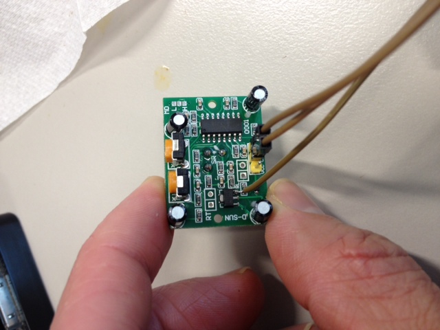
I don't know why i wake-up this arduino every 30 seconds, the sketch was fabricated by combine 2 or 3 other sketches to this one ( with help from @AWI )
So if there are some tweaking thing to do, do not hesitate and change the sketch as you think it must be@icebob what's the sketch you using /testing ?
There's more than meets the eye
-
@carlierd said:
Hello,
You need to power the motion sensor all time as you want to detect any mouvement and not only every 2 minutes.
Caution, in your sketch, the battery level is sent at the beginning and at the end.
Did you tweak the motion sensor ?? Not tested yet but it seems that modification could (must ?) be done to reduce power consumption (LINK).
Why do you wake-up the arduino every 30 seconds ? For temperature, every 5 or 15 minutes is enough.
Sure i modded the motion sensor as shown in the hyperlink , modded it this way :
I don't know why i wake-up this arduino every 30 seconds, the sketch was fabricated by combine 2 or 3 other sketches to this one ( with help from @AWI )
So if there are some tweaking thing to do, do not hesitate and change the sketch as you think it must be@icebob what's the sketch you using /testing ?
@the-cosmic-gate No specific reason to have a 30 second interval. You can just change the SLEEP_TIME to whatever eg. 5 minutes == 300000UL. The pin change interrupt is present in the code..
gw.sleep(INTERRUPT,CHANGE, SLEEP_TIME); -
@icebob could you share us you're code ?
-
@the-cosmic-gate sorry, I'm working a big complex sketch, I can't share my code currently.
@icebob said:
@the-cosmic-gate sorry, I'm working a big complex sketch, I can't share my code currently.
Big and complex sounds interesting :)
Could you maybe share us a sneak peak ;-) -
@the-cosmic-gate Nothing special. I made a big sketch, which contains 7-8 sensors (DHT, Si7021, MQ-2/9, PIR, Door magnet, Light, battery) reading code because I would like to upload the same sketch to all nodes and configurate it on controller side, which sensors is on the node and need to read.
But currently I reached the limit with I2C includes, so I need to think over this solution. -
@the-cosmic-gate Did you solved your power consumption issue ?
@carlierd said:
@the-cosmic-gate Did you solved your power consumption issue ?
Not yet, this because we moved to oneother house and didn't have the time now .
Also i had to disconnect and reconect all te sensors and domotica in this new house -
I just finished my first motion sensor node and the power consumption in idle is about 75uA. Could be better but not too bad ;)
The only thing is that the range is a little bit low for good detection. It's between 1 and 3 meters ...David.
@carlierd said:
I just finished my first motion sensor node and the power consumption in idle is about 75uA. Could be better but not too bad ;)
The only thing is that the range is a little bit low for good detection. It's between 1 and 3 meters ...David.
Hello David
Could you share what and how ? :)
Thnx
-
Hello,
This is the code I use but it's not perfect especially with the battery report.
The principle is as follow when the sensor start:
- node in sleep mode with interrupt enable
- if a move is detected, the detection is reported to the gateway
- the node then go in sleep mode WITHOUT interrupt for 5 minutes
- then the node return to sleep mode with interrupt enable
This is to avoid having many report (and power consumption) to the gateway.
The code (not perfect ! I have to rework on it but it's ok for the moment):
/**
 * The MySensors Arduino library handles the wireless radio link and protocol
 * between your home built sensors/actuators and HA controller of choice.
 * The sensors forms a self healing radio network with optional repeaters. Each
 * repeater and gateway builds a routing tables in EEPROM which keeps track of the
 * network topology allowing messages to be routed to nodes.
 *
 * Created by Henrik Ekblad <henrik.ekblad@mysensors.org>
 * Copyright (C) 2013-2015 Sensnology AB
 * Full contributor list: https://github.com/mysensors/Arduino/graphs/contributors
 *
 * Documentation: http://www.mysensors.org
 * Support Forum: http://forum.mysensors.org
 *
 * This program is free software; you can redistribute it and/or
 * modify it under the terms of the GNU General Public License
 * version 2 as published by the Free Software Foundation.
 *
 */

/**************************************************************************************/
/* Motion sensor.                                                                     */
/*                                                                                    */
/* Version     : 1.1.5                                                                */
/* Date        : 30/01/2016                                                           */
/* Modified by : David Carlier                                                        */
/**************************************************************************************/
/*                                ---------------                                     */
/*                            RST |             |  A5                                 */
/*                            RX  |             |  A4                                 */
/*                            TX  |   ARDUINO   |  A3                                 */
/*     RFM69 (DIO0) --------- D2  |     UNO     |  A2                                 */
/*           Motion --------- D3  |             |  A1                                 */
/*            Power --------- D4  | ATMEGA 328p |  A0                                 */
/*              +3v --------- VCC |             | GND --------- GND                   */
/*              GND --------- GND |  8MHz int.  | REF                                 */
/*                            OSC |             | VCC --------- +3v                   */
/*                            OSC |             | D13 --------- RFM69 (SCK)           */
/*                            D5  |             | D12 --------- RFM69 (MISO)          */
/*                            D6  |             | D11 --------- RFM69 (MOSI)          */
/*                            D7  |             | D10 --------- RFM69 (NSS)           */
/*                            D8  |             |  D9                                 */
/*                                ---------------                                     */
/*                                                                                    */
/* +3v = 2*AA                                                                         */
/*                                                                                    */
/**************************************************************************************/

#include <SPI.h>
#include <MySensor.h>
#include <MyTransportRFM69.h>
#include <MySigningAtsha204Soft.h>

//Constants
#define SKETCH_NAME           "Motion Sensor"
#define SKETCH_VERSION        "1.1.5"
#define CHILD_ID              0
#define CHILD_ID_VOLTAGE      1
#define DIGITAL_INPUT_SENSOR  3
#define BATTERY_REPORT_CYCLE  4   //Report each hour (4 * 15')

//Misc. variables
uint8_t switchState = 2;
unsigned long SLEEP_TIME = 820000; // Sleep time between reads (in milliseconds) (close to 15')
unsigned long SLEEP_TIME2 = 275000; // Sleep time after int. (in milliseconds) (close to 5')
uint8_t cycleInProgress = 0;
uint8_t firstReportDone = 0;
uint8_t firstReportWithZeroDone = 0;

//Construct MySensors library
MySigningAtsha204Soft signer;
MyHwATMega328 hw;
MyTransportRFM69 transport;
MySensor node(transport, hw, signer);
MyMessage msgSwitch(CHILD_ID, V_TRIPPED);
MyMessage msgVolt(CHILD_ID_VOLTAGE, V_VOLTAGE);

/**************************************************************************************/
/* Initialization                                                                     */
/**************************************************************************************/
void setup()
  {
  //Get time (for setup duration)
  #ifdef DEBUG
    unsigned long startTime = millis();
  #endif

  //Start MySensors and send the Sketch Version Information to the Gateway
  node.begin();
  node.sendSketchInfo(SKETCH_NAME, SKETCH_VERSION);

  //Setup the button
  pinMode(DIGITAL_INPUT_SENSOR, INPUT);

  //Register all sensors
  node.present(CHILD_ID, S_MOTION);
  node.present(CHILD_ID_VOLTAGE, S_MULTIMETER);

  //Print setup debug
  #ifdef DEBUG
    int duration = millis() - startTime;
    Serial.print("[Setup duration: "); Serial.print(duration, DEC); Serial.println(" ms]");
  #endif
  }

/**************************************************************************************/
/* Main loop                                                                          */
/**************************************************************************************/
void loop()
  {
  //Get time (for a complete loop)
  #ifdef DEBUG
    unsigned long startTime = millis();
  #endif

  //Read digital motion value
  uint8_t value = digitalRead(DIGITAL_INPUT_SENSOR);

  //Get voltage for battery capacity report (add 0.1v to the read value)
  float realVoltage = (getVoltage() / 100.0) + 0.1;
  int batteryPcnt = realVoltage * 100 / 3.0;
  if (batteryPcnt > 100) {batteryPcnt = 100;}

  //Check is state change
  if (value != switchState)
    {
    //Report result if not first loop
    if (firstReportDone != 0)
      {
      node.send(msgSwitch.set(value==HIGH ? 1 : 0));
      }

    //Store result
    switchState = value;
    }

  //Report data to the gateway each hour
  if (cycleInProgress >= BATTERY_REPORT_CYCLE || firstReportDone == 0)
    {
    node.send(msgSwitch.set(value==HIGH ? 1 : 0));
    node.send(msgVolt.set(realVoltage, 2));
    node.sendBatteryLevel(batteryPcnt);
    cycleInProgress = 0;
    firstReportDone = 1;
    }

  //Change cycle number
  cycleInProgress++;

  //Print debug
  #ifdef DEBUG
    Serial.print("Value is ");
    Serial.print(value, 1);
    Serial.print("   ");
    Serial.print("Cycle is ");
    Serial.print(cycleInProgress, 1);
    Serial.print("   ");
    Serial.print(realVoltage);
    Serial.print(" v");
    int duration = millis() - startTime;
    Serial.print("   ");
    Serial.print("["); Serial.print(duration, DEC); Serial.println(" ms]");
    Serial.flush();
  #endif

  //Check if the motion was triggered and if it's not the first report
  if (switchState == 0 && firstReportWithZeroDone == 1)
    {
    //Sleep 5' without interrupt
    node.sleep(SLEEP_TIME2);
    }

  //Check if it's the first loop
  if (switchState == 0 && firstReportWithZeroDone == 0)
    {
    firstReportWithZeroDone = 1;
    }

  //Sleep until something happens with the sensor
  node.sleep(DIGITAL_INPUT_SENSOR-2, CHANGE, SLEEP_TIME);
  }

/**************************************************************************************/
/* Allows to get the real Vcc (return value * 100).                                   */
/**************************************************************************************/
int getVoltage()
  {
  const long InternalReferenceVoltage = 1056L;
  ADMUX = (0<<REFS1) | (1<<REFS0) | (0<<ADLAR) | (1<<MUX3) | (1<<MUX2) | (1<<MUX1) | (0<<MUX0);
  delay(50);  // Let mux settle a little to get a more stable A/D conversion
  //Start a conversion
  ADCSRA |= _BV( ADSC );
  //Wait for it to complete
  while (((ADCSRA & (1<<ADSC)) != 0));
  //Scale the value
  int result = (((InternalReferenceVoltage * 1023L) / ADC) + 5L) / 10L;
  return result;
  }
On one sensor I tweak the PIR (remove regulator and diode) but on a second one, I just plug the 3 v to the H pin (see other topic on the forum).
Working correctly for the moment (one month) but it depends on the presence in the house.
David.