Skip to content
  • OpenHardware.io
  • Categories
  • Recent
  • Tags
  • Popular
Skins
  • Light
  • Brite
  • Cerulean
  • Cosmo
  • Flatly
  • Journal
  • Litera
  • Lumen
  • Lux
  • Materia
  • Minty
  • Morph
  • Pulse
  • Sandstone
  • Simplex
  • Sketchy
  • Spacelab
  • United
  • Yeti
  • Zephyr
  • Dark
  • Cyborg
  • Darkly
  • Quartz
  • Slate
  • Solar
  • Superhero
  • Vapor

  • Default (No Skin)
  • No Skin
Collapse
Brand Logo
  1. Home
  2. My Project
  3. 2 channel in wall dimmer
  • Getting Started
  • Controller
  • Build
  • Hardware
  • Download/API
  • Forum
  • Store

2 channel in wall dimmer

Scheduled Pinned Locked Moved My Project
54 Posts 15 Posters 24.2k Views 26 Watching
  • Oldest to Newest
  • Newest to Oldest
  • Most Votes
Reply
  • Reply as topic
Log in to reply
This topic has been deleted. Only users with topic management privileges can see it.
  • F Offline
    F Offline
    fleinze
    wrote on last edited by
    #3

    Could you share schematics?
    How many Watt/Ampere are you trying to dim? Is residual heat from the transistore/thyristors? an issue?

    1 Reply Last reply
    0
    • D Offline
      D Offline
      Denke
      Hardware Contributor
      wrote on last edited by Denke
      #4

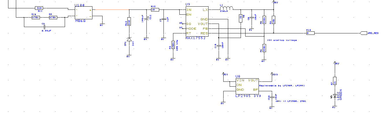
      Here is the schematic of the conversion from 240 V to 5 V. It could work for 110 V as well but that needs to be simulated.

      Be aware that by this type of design with the transformer less design considerations needs to be taken when connecting computers and other stuff. So my recommendation would be to program everything without 240 V attached.

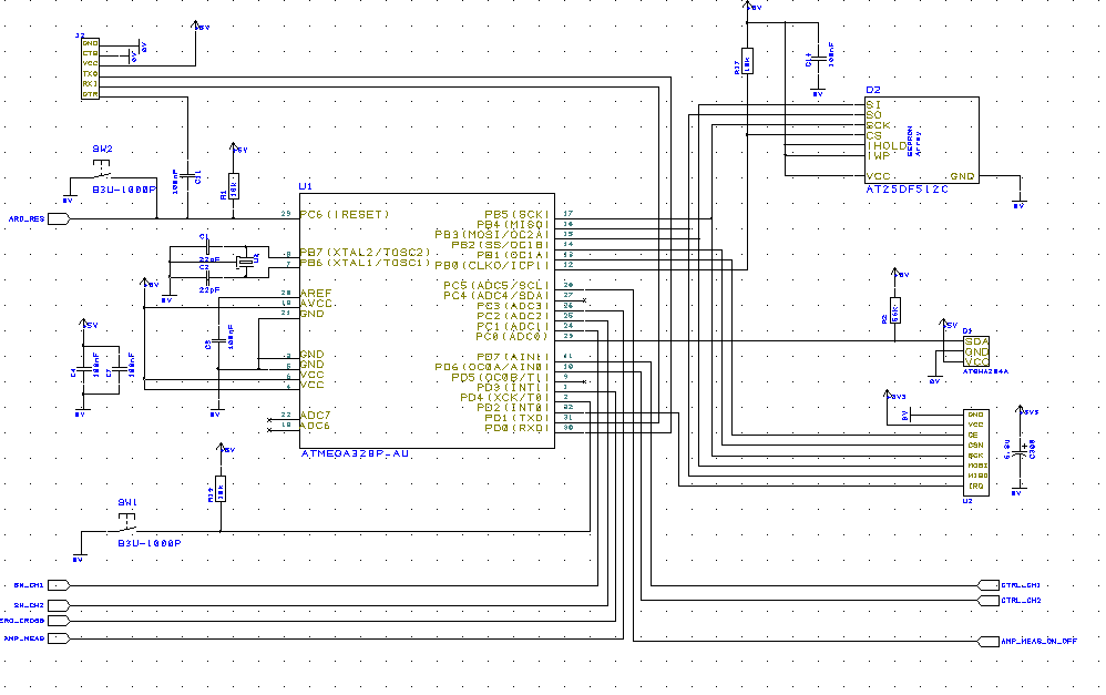
      I have used the 328P

      The picture below shows the AC to DC conversion. This design can handle ~30mA on the 5V side.
      The AC is on the left hand side. the 0.33 uF capacitor in series on the 240 sets the maximum current, which should be around 10 mA on the AC side (Theoretically 25mA, simulated 10mA).

      Be aware that not all values in the design below is correct to get the MAX 17552 to work.
      upload-dbd1cc29-6fbd-4c13-8ea9-e08079fa11cf

      RaspberryPi-Openhab

      1 Reply Last reply
      0
      • D Offline
        D Offline
        Denke
        Hardware Contributor
        wrote on last edited by Denke
        #5

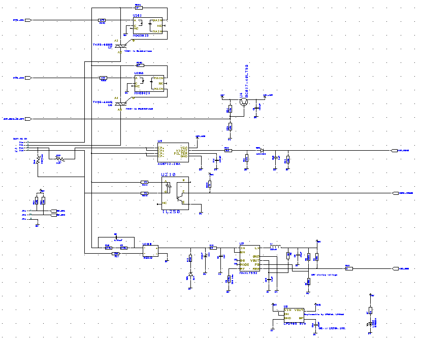
        Ther Triac in the design is T405-600B which should be able to handle 4A current if i read the spec right. I have not tested it yet so i dont know how much power dissipation there will be

        RaspberryPi-Openhab

        1 Reply Last reply
        0
        • sundberg84S Offline
          sundberg84S Offline
          sundberg84
          Hardware Contributor
          wrote on last edited by
          #6

          Nice!
          It would be nice if you could explain how you think about safety with high voltage.
          We have had several good discussions you maybe seen, but whats your thoughts?

          Controller: Proxmox VM - Home Assistant
          MySensors GW: Arduino Uno - W5100 Ethernet, Gw Shield Nrf24l01+ 2,4Ghz
          MySensors GW: Arduino Uno - Gw Shield RFM69, 433mhz
          RFLink GW - Arduino Mega + RFLink Shield, 433mhz

          1 Reply Last reply
          0
          • D Offline
            D Offline
            Denke
            Hardware Contributor
            wrote on last edited by
            #7

            What i mean is that care needs to be taken when using this type of design when it comes to handling. The main thing is if the 0.33uF capacitor breaks then there could be 240 V on the low voltage side, so as long as you handle the equipment with respect to this then i believe it will be safe. That's why i will only use the inbuilt wall switch together with this as that one is rated for the 240 volts.

            Also there can be a grounding issue as this design is floating. This is why i will not connect my programmer to this with 240 Volts connected, most likely nothing will happen, but better be safe than sorry, don't want to damage my computer.

            The only thing i think i will add in the design is a thermal fuse to be on the safe side. I have one of these ACS712 that I can read the current, but then everything is up to the programming to make sure you don't have any over current in the system that causes heat.
            I have also added 0.75 mm isolation distance between traces on the board as well as having thick enough lines for the 4A that I have designed for.

            RaspberryPi-Openhab

            1 Reply Last reply
            0
            • D Offline
              D Offline
              Denke
              Hardware Contributor
              wrote on last edited by
              #8

              I have now made a new layout on this where i have added a Thermal cut off resistor as well. This made me rearrange some things on the board. At the moment I am still investigating the best triac to use and if it will be "quiet" enough on the line if i use the snubberless version of the triac.

              RaspberryPi-Openhab

              1 Reply Last reply
              0
              • D Offline
                D Offline
                Denke
                Hardware Contributor
                wrote on last edited by
                #9

                Here is the current schematic of the design.
                upload-47a0e04d-4399-4848-8907-26dba43bda7f
                upload-59b644b8-c4ac-4f6d-bbef-c13bb4dac5e9

                RaspberryPi-Openhab

                1 Reply Last reply
                0
                • sundberg84S Offline
                  sundberg84S Offline
                  sundberg84
                  Hardware Contributor
                  wrote on last edited by
                  #10

                  Interesting! Im following this since im also trying to figure out a good in-wall sollution.

                  Controller: Proxmox VM - Home Assistant
                  MySensors GW: Arduino Uno - W5100 Ethernet, Gw Shield Nrf24l01+ 2,4Ghz
                  MySensors GW: Arduino Uno - Gw Shield RFM69, 433mhz
                  RFLink GW - Arduino Mega + RFLink Shield, 433mhz

                  1 Reply Last reply
                  0
                  • D Offline
                    D Offline
                    Denke
                    Hardware Contributor
                    wrote on last edited by Denke
                    #11

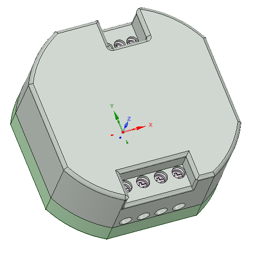
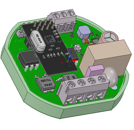
                    First attempt to see how a box could look like
                    Diameter 56 mm 50 mmside to side
                    upload-42fbc227-8fec-41e8-b99a-6196e906d5d3
                    upload-d953e37e-f381-4354-89b4-819d5907b5f0

                    RaspberryPi-Openhab

                    1 Reply Last reply
                    4
                    • hekH Offline
                      hekH Offline
                      hek
                      Admin
                      wrote on last edited by
                      #12

                      Very nice @Denke!

                      1 Reply Last reply
                      0
                      • S Offline
                        S Offline
                        stephenmhall
                        wrote on last edited by
                        #13

                        I like it, what sort of switch would be on the wall?

                        1 Reply Last reply
                        0
                        • mfalkviddM Offline
                          mfalkviddM Offline
                          mfalkvidd
                          Mod
                          wrote on last edited by
                          #14

                          This project is in-wall only. You can control it any way you like - from smartphone, PC, remotes or physical switches.

                          1 Reply Last reply
                          0
                          • ahmedadelhosniA Offline
                            ahmedadelhosniA Offline
                            ahmedadelhosni
                            wrote on last edited by
                            #15

                            I like the project very much.

                            How are you sure that this hardware circuit is suitable and safe to give stable output ? I am asking that because I studied electronics but still see that a lot of knowledge are missing to implement such circuit. so, how did you learn this ? This is not a normal full wave rectifier :) It looks professional

                            Thanks.

                            1 Reply Last reply
                            0
                            • ? Offline
                              ? Offline
                              A Former User
                              wrote on last edited by
                              #16

                              Very nice Denke,

                              I suspect this unit is going to be mounted in wall behind the existing switch and wonder if existing switch can be used to control the dimming. The switch have to have spring return naturally.

                              Excellent work
                              Goran

                              1 Reply Last reply
                              0
                              • J Offline
                                J Offline
                                jemish
                                wrote on last edited by
                                #17

                                can we control Celling fan using this dimmer.

                                1 Reply Last reply
                                0
                                • sundberg84S Offline
                                  sundberg84S Offline
                                  sundberg84
                                  Hardware Contributor
                                  wrote on last edited by
                                  #18

                                  @Denke Can you share your files for this design?
                                  It would be awesome and this looks great!

                                  Controller: Proxmox VM - Home Assistant
                                  MySensors GW: Arduino Uno - W5100 Ethernet, Gw Shield Nrf24l01+ 2,4Ghz
                                  MySensors GW: Arduino Uno - Gw Shield RFM69, 433mhz
                                  RFLink GW - Arduino Mega + RFLink Shield, 433mhz

                                  1 Reply Last reply
                                  0
                                  • D Offline
                                    D Offline
                                    Denke
                                    Hardware Contributor
                                    wrote on last edited by
                                    #19

                                    Hi all
                                    I will try to answer your questions.

                                    Q: what sort of switch would be on the wall?
                                    For this design i would recommend that you use 230 V rated switch to control the dimmer. The output is still only 0V that you switch on and off. But the design is made in such a way that if you get short circuit on the capacitor in series in to the rectifier there can be 230 V on the input pins ( very unlikely because of other things will burn) but it can happen.

                                    Q: How are you sure that this hardware circuit …….
                                    Doing a little benchmark and understand how dimmers and switches from NEXA or similar are working. Actually I ripped them apart and found out that they were using transformer less designs. From that I Googled this and read up on the topic as well as discussed this with colleges of mine. I then changed some parts as the transformerless design would in simulation not give more than 10mA so I added the MAX 17552 circuit in between and set the input voltage to 24 V with the zener diode and by that I will be able to draw about 30 mA (starting current of the circuit that I tested is around 24 mA).
                                    Q: I suspect this unit is going to be mounted in wall behind……..
                                    Yes of course but just use it as the switch, what I mean is that don’t use at ordinary switch were 230 V is applied. The circuit is designed to just feel a logic zero on one of the inputs. ( just make sure that you read my first reply above for safety reasons)
                                    Q: can we control Celling fan using this dimmer.
                                    Should not be a problem as I have used Triacs that are made for inductive load (not tested though). But the fan should not consume more than 4A. I also have not tested from a heat perspective how much power I can have running in the system. It might be less than the 2 channels times 4A.

                                    RaspberryPi-Openhab

                                    1 Reply Last reply
                                    2
                                    • D Offline
                                      D Offline
                                      Denke
                                      Hardware Contributor
                                      wrote on last edited by
                                      #20

                                      I have not descided yet if this is something i will sell or not so before i take that descision i will not share the actual design files but I will be happy to answer questions around the design and the considerations i have taken.

                                      I might post a question later on if someone wants to join on first ordering for the prototypes/functional version, as this is the first step, primaraly to equip my house with these gadgets. In such a case i will offer those dimmers for a very low cost

                                      RaspberryPi-Openhab

                                      1 Reply Last reply
                                      0
                                      • hekH Offline
                                        hekH Offline
                                        hek
                                        Admin
                                        wrote on last edited by
                                        #21

                                        So, what is the problem of sharing design as open hardware and at the same time sell your boards assembled?

                                        D 1 Reply Last reply
                                        0
                                        • hekH hek

                                          So, what is the problem of sharing design as open hardware and at the same time sell your boards assembled?

                                          D Offline
                                          D Offline
                                          Denke
                                          Hardware Contributor
                                          wrote on last edited by
                                          #22

                                          @hek Its more that i at this moment have not gone through the pros and cons of open hardware. And this is something i will read up on. So Im not saying that i will not share, but i need my time to go through it.

                                          RaspberryPi-Openhab

                                          1 Reply Last reply
                                          4
                                          Reply
                                          • Reply as topic
                                          Log in to reply
                                          • Oldest to Newest
                                          • Newest to Oldest
                                          • Most Votes


                                          18

                                          Online

                                          11.7k

                                          Users

                                          11.2k

                                          Topics

                                          113.0k

                                          Posts


                                          Copyright 2019 TBD   |   Forum Guidelines   |   Privacy Policy   |   Terms of Service
                                          • Login

                                          • Don't have an account? Register

                                          • Login or register to search.
                                          • First post
                                            Last post
                                          0
                                          • OpenHardware.io
                                          • Categories
                                          • Recent
                                          • Tags
                                          • Popular