💬 Easy/Newbie PCB for MySensors
-
@chuckconnors I will think about how to bypass the voltage regulator, but anyway you need to solder something (either a jumper or voltage regulator). Do you have any tips?
Good tip with the raw/pwr. If you have not cut the pcb you also have the proto area where the first is VCC (3.3) and second is Gnd.
@sundberg84 I was able to use your marked up image to successfully build two nodes without problem. Thanks again for the help with hooking things up and for providing the board for purchase as well. I was able to build the whole thing in about 10 minutes even with my limited soldering abilities.
The only gripe I have is that one of my boards had a hole for the 4.7uF cap that wasn't completely drilled out. It was easy enough to just solder to the nearby ground. This is a dirtyboards quality control issue. I'm hoping not to see this on any of my other boards. I guess I'll have to inspect them before adding the components for future nodes.
All the best to you!
-
@chuckconnors! Thank you for those kind words - it is appreciated.
To save your node without the hole for 4.7uF you can solder it directly on the nrf if needed. I hope you have great use for the boards in the future. -
@chuckconnors! Thank you for those kind words - it is appreciated.
To save your node without the hole for 4.7uF you can solder it directly on the nrf if needed. I hope you have great use for the boards in the future.@sundberg84 I'm about to make an aliexpress order and would like to get some voltage regulators. I scanned through the post but didn't see a BoM. Can you please tell me the part number for the voltage regulator used?
-
The boards have arrived!!! YES!!
It took about 3 weeks between the shipping status and my mailbox. I guess I cant complain.
@sundberg84 I do have another question.
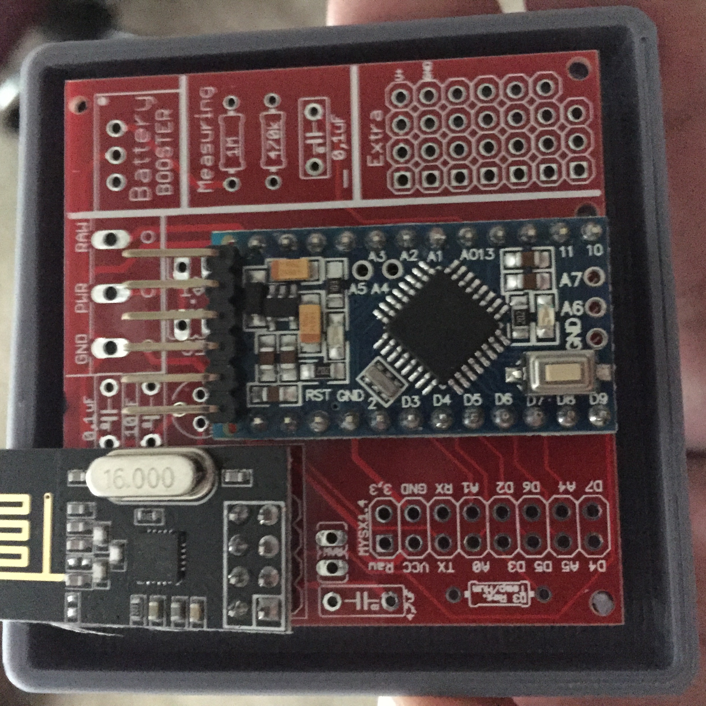
Are the pins A6, A7 and the extra ground (next to A6) connected at all? is it worth to solder a connector on them to the PCB?
Edit: or maybe 2...
D8 does not seem to be used, is this correct?Cheers
-
The boards have arrived!!! YES!!
It took about 3 weeks between the shipping status and my mailbox. I guess I cant complain.
@sundberg84 I do have another question.
Are the pins A6, A7 and the extra ground (next to A6) connected at all? is it worth to solder a connector on them to the PCB?
Edit: or maybe 2...
D8 does not seem to be used, is this correct?Cheers
From the look of the design files, your are correct, A6 A7 and D8 are not connected. The GND pin is connected to the GND on the PCB, so just for the sake of ticking all the boxes, i would have that connected to the PCB from the Arduino.
Wait for @sundberg84's confirmation on my details, but from what i understand my observations stated above are correct. As i say though, wait for Sundberg's confirmation. I wish you happy tinkering with yet another awesome contribution from Sundberg. ;)
-
@barduino A6 and A7 is not connected, but as @Samuel235 said - the ground is connected to the PCB with a line to ground source. There are three grounds connected from the arduino (I dont know why exactly) and they are all connected/wired on the PCB.
-
@Samuel235 , @sundberg84 , thank you both
-
@sundberg84
Hi,
The suppler has an similar product, is it usable for the same purpose?0.8-3.3V v. 2-5V ?
thanks -
@Barna Its possible to use this, but you want as low as possible and not 2V. This means using 2xAA (3v max) you only have a range down to 2V before the booster wont work anymore. At this point if you have not changed the fuses in the arduino it will fail. I guess you could use this with 3XAA (4.5V) as well if thats what you are aiming for.
Controller: Proxmox VM - Home Assistant
MySensors GW: Arduino Uno - W5100 Ethernet, Gw Shield Nrf24l01+ 2,4Ghz
MySensors GW: Arduino Uno - Gw Shield RFM69, 433mhz
RFLink GW - Arduino Mega + RFLink Shield, 433mhz -
@Barna Its possible to use this, but you want as low as possible and not 2V. This means using 2xAA (3v max) you only have a range down to 2V before the booster wont work anymore. At this point if you have not changed the fuses in the arduino it will fail. I guess you could use this with 3XAA (4.5V) as well if thats what you are aiming for.
@sundberg84
ok, thanks. In that case some power will be left in the AAs, Am I right?
what do you advice if I need 5V for some sensors but I would like to use battery?
3xAA, 4xAA, 9V with regulator - is the lifetime of battery is efficient in this case ? -
@Barna
That is a hard question, because i try to do 3.3v for battery and 5v for regulated power.
I have 1 node at this point running on a 9v battery and 5v arduino (motion detector) but without booster and battery measurment. I have removed led and at this point i have had it run for 4 weeks. I have NO clue about batterylife but I do not expect it to work pretty long. -
mmmm i think that al this work, for a 4 weeks working sensor is not a good solution for a home automation system....
Why can a Zwave or 433Mhz motion sensor work for more then a year...
Is my biggest question..
Forum linkIs there relay now solution for a battery live for a year...
Other bord, other sketch, other regulator, other battery...or...
Domoticz, with a lot of working hardware, include mysensors :-)
OpenPLI, RuneAudio, Solarmeter, etc......Not a great builder of software and hardware, more a user...
Only i try to do my best :-( -
mmmm i think that al this work, for a 4 weeks working sensor is not a good solution for a home automation system....
Why can a Zwave or 433Mhz motion sensor work for more then a year...
Is my biggest question..
Forum linkIs there relay now solution for a battery live for a year...
Other bord, other sketch, other regulator, other battery...or...
@Dylano Google for low power arduino mini. Or arduino mini on battery. I've got one running now for half a year on two aaa batteries. Only lost 10% or something.
(Quickest is to remove the led and the voltage regulator) -
@Dylano Im not sure if I understand what you mean. This PCB does not support 433mhz or Zwave. You need to make that a question in the forum. I have nodes with this PCB now almost running for a year, and reporting good battery level.
As Sander told you above, remove led and voltage regulator on a 3.3v arduino and you will run a mysensor node for a year:

-
This post is deleted!
-
This post is deleted!
@Sander-Teunissen I have some rev6 that I am willing to sell. Let me know if you are interested.
-
@Dylano Im not sure if I understand what you mean. This PCB does not support 433mhz or Zwave. You need to make that a question in the forum. I have nodes with this PCB now almost running for a year, and reporting good battery level.
As Sander told you above, remove led and voltage regulator on a 3.3v arduino and you will run a mysensor node for a year:
@sundberg84 said:
I have nodes with this PCB now almost running for a year, and reporting good battery level.
I see that battery measuring is not working in my case.
Can you post your sketch for a DHT22 or dallas sensor? Because readVCC.h does not work with a step up booster and 2x AA batteries connected, it seems.. -
@lxz This is my code (Note dev branch!) for DHT22 incl battery measuring (2xAA).
The reason for readVCC:h does not work is that you measure after the booster = always 3.3V!// Enable debug prints #define MY_DEBUG // Enable and select radio type attached #define MY_RADIO_NRF24 //#define MY_RADIO_RFM69 #define MY_NODE_ID 15 #include <SPI.h> #include <MySensor.h> #include <DHT.h> #define CHILD_ID_HUM 0 #define CHILD_ID_TEMP 1 #define HUMIDITY_SENSOR_DIGITAL_PIN 3 unsigned long SLEEP_TIME = 600000; // Sleep time between reads (in milliseconds) #define SKETCH_NAME "UtomhusHumSyd #15" // Change to a fancy name you like #define SKETCH_VERSION "1.0" // Your version DHT dht; float lastTemp; float lastHum; boolean metric = true; MyMessage msgHum(CHILD_ID_HUM, V_HUM); MyMessage msgTemp(CHILD_ID_TEMP, V_TEMP); //========================= // BATTERY VOLTAGE DIVIDER SETUP // 1M, 470K divider across battery and using internal ADC ref of 1.1V // Sense point is bypassed with 0.1 uF cap to reduce noise at that point // ((1e6+470e3)/470e3)*1.1 = Vmax = 3.44 Volts // 3.44/1023 = Volts per bit = 0.003363075 #define VBAT_PER_BITS 0.003363075 #define VMIN 1.9 // Vmin (radio Min Volt)=1.9V (564v) #define VMAX 3.0 // Vmax = (2xAA bat)=3.0V (892v) int batteryPcnt = 0; // Calc value for battery % int batLoop = 0; // Loop to help calc average int batArray[3]; // Array to store value for average calc. int BATTERY_SENSE_PIN = A0; // select the input pin for the battery sense point //========================= void setup() { analogReference(INTERNAL); // For battery sensing delay(500); // Allow time for radio if power used as reset dht.setup(HUMIDITY_SENSOR_DIGITAL_PIN); metric = getConfig().isMetric; } void presentation() { // Send the Sketch Version Information to the Gateway // Send the Sketch Version Information to the Gateway sendSketchInfo(SKETCH_NAME, SKETCH_VERSION); // Register all sensors to gw (they will be created as child devices) present(CHILD_ID_HUM, S_HUM); present(CHILD_ID_TEMP, S_TEMP); } void loop() { delay(500); // Allow time for radio if power used as reset delay(dht.getMinimumSamplingPeriod()); // Fetch temperatures from DHT sensor float temperature = dht.getTemperature(); if (isnan(temperature)) { Serial.println("Failed reading temperature from DHT"); } else if (temperature != lastTemp) { lastTemp = temperature; if (!metric) { temperature = dht.toFahrenheit(temperature); } send(msgTemp.set(temperature, 1)); Serial.print("T: "); Serial.println(temperature); } // Fetch humidity from DHT sensor float humidity = dht.getHumidity(); if (isnan(humidity)) { Serial.println("Failed reading humidity from DHT"); } else if (humidity != lastHum) { lastHum = humidity; send(msgHum.set(humidity, 1)); Serial.print("H: "); Serial.println(humidity); } batM(); sleep(SLEEP_TIME); //sleep a bit } void batM() //The battery calculations { delay(500); // Battery monitoring reading int sensorValue = analogRead(BATTERY_SENSE_PIN); delay(500); // Calculate the battery in % float Vbat = sensorValue * VBAT_PER_BITS; int batteryPcnt = static_cast<int>(((Vbat-VMIN)/(VMAX-VMIN))*100.); Serial.print("Battery percent: "); Serial.print(batteryPcnt); Serial.println(" %"); // Add it to array so we get an average of 3 (3x20min) batArray[batLoop] = batteryPcnt; if (batLoop > 2) { batteryPcnt = (batArray[0] + batArray[1] + batArray[2] + batArray[3]); batteryPcnt = batteryPcnt / 3; if (batteryPcnt > 100) { batteryPcnt=100; } Serial.print("Battery Average (Send): "); Serial.print(batteryPcnt); Serial.println(" %"); sendBatteryLevel(batteryPcnt); batLoop = 0; } else { batLoop++; } }```