💬 My Slim 2AA Battery Node
-
Hello :)
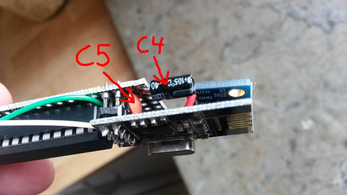
In the BOM file there is C5 capacitor, but I can't figure out where it does stand on the board. Can you help please ? -
Hello :)
In the BOM file there is C5 capacitor, but I can't figure out where it does stand on the board. Can you help please ?@carmelo42
-
thanks @m26872 :)
I have ordered smd capacitors for c5 ... but I think it will be good :)
Can you explain the role of the C5 cap ? I know that C4 is for decoupling for the radio, but C1, C2, C3 and C4 : I don't know !
Another little question :)
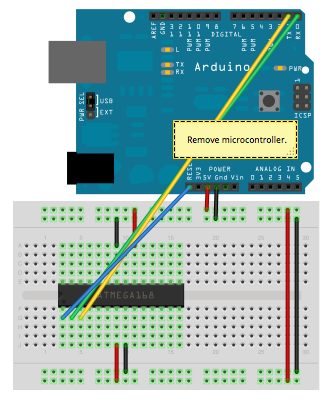
with my brand new atmega328p, I have burned the bootloader with an arduino uno with the "ArduinoISP" in it.After that, I have sent the sketch with another arduino (with it's own atmega removed) and my brand new atmega like that :
https://www.arduino.cc/en/uploads/Tutorial/ArduinoUSBSerialSimple.pngIs it possible to put the sketch in the atmega directly on the slim2aabatterynode board ? With an FTDI serial device ?
-
thanks @m26872 :)
I have ordered smd capacitors for c5 ... but I think it will be good :)
Can you explain the role of the C5 cap ? I know that C4 is for decoupling for the radio, but C1, C2, C3 and C4 : I don't know !
Another little question :)
with my brand new atmega328p, I have burned the bootloader with an arduino uno with the "ArduinoISP" in it.After that, I have sent the sketch with another arduino (with it's own atmega removed) and my brand new atmega like that :
https://www.arduino.cc/en/uploads/Tutorial/ArduinoUSBSerialSimple.pngIs it possible to put the sketch in the atmega directly on the slim2aabatterynode board ? With an FTDI serial device ?
@carmelo42 Sorry for a late reply. In short C2 is to reset the avr, C1 and C3 are to decouple the avr. And C4,C5 for the radio as you say. The caps are there as a recommendation, precaution, stability, etc, and all of them are not always necessary when it's supplied by battery.
And yes, the idea of the FTDI-6-pin-header and bootloader is to provide ability to load sketches the normal Auduino way with FTDI and Arduino IDE. -
This post is deleted!
-
Hello, I have built a number of these sensor nodes and really like the generic design!
However I have run into trouble when trying to build a power meter with a photo sensor.
I am using the code from MySensors but also tried other sources but my problem is that the digital pin i am using (D3) dont drop enough for the sensor to treat it as digital 0 as it stays at 2.3 V with a 2 AA battery power attachedWhen trying the pulse sensor with external power it works perfect so it seems like D3 is floating which also is confirmed when I measure on D3 without the sensor attached. (approx 2.7V)
I have used this row in my sketch pinMode(DIGITAL_INPUT_SENSOR,INPUT_PULLUP);Any clues what I can try?
@miljume said in 💬 My Slim 2AA Battery Node:
INPUT_PULLUP
What kind of sensor do you use? Some sensors have an analog and digital output. The Digital should return either 0V or VCC while the analog returns all analog values between 0V and VCC.
You could try an external pulldown resistor of 10k to ground if you think the pin is floating.
Another approach is to elaborate with a photoresistor only and to get a clean 0/1 use an transistor. If the voltage drops to low though for the pin to get a clear 1 (2.4v on 3.3v atmega) you might need a DC/DC step up booster.
Controller: Proxmox VM - Home Assistant
MySensors GW: Arduino Uno - W5100 Ethernet, Gw Shield Nrf24l01+ 2,4Ghz
MySensors GW: Arduino Uno - Gw Shield RFM69, 433mhz
RFLink GW - Arduino Mega + RFLink Shield, 433mhz -
@miljume said in 💬 My Slim 2AA Battery Node:
INPUT_PULLUP
What kind of sensor do you use? Some sensors have an analog and digital output. The Digital should return either 0V or VCC while the analog returns all analog values between 0V and VCC.
You could try an external pulldown resistor of 10k to ground if you think the pin is floating.
Another approach is to elaborate with a photoresistor only and to get a clean 0/1 use an transistor. If the voltage drops to low though for the pin to get a clear 1 (2.4v on 3.3v atmega) you might need a DC/DC step up booster.
@sundberg84 Thank you for your feedback! I used the design found here so the sensor is OK. I had also tried to use a pulldown resistor but it showed that I had used too low value. When I use 10k as you suggested it worked like a charm, thank you! What I dont understand is why I should need the pulldown resistor in the first place? Shouldn't it be possible to solve that in the software?
-
@sundberg84 Thank you for your feedback! I used the design found here so the sensor is OK. I had also tried to use a pulldown resistor but it showed that I had used too low value. When I use 10k as you suggested it worked like a charm, thank you! What I dont understand is why I should need the pulldown resistor in the first place? Shouldn't it be possible to solve that in the software?
@miljume - I dont think you can solve a floating pin in the software. Im not that experienced with internal pullups either so someone else have to answer that. Good you have it working though!
-
Internal pull-up resistors have 20-50k resistance. It may be not enough.
-
For those looking to 3d print a case for this, if you cant find the right sized ducting, I designed one thats unobtrusive:
-
Hello, i made a few. is someone interested in these nodes in Germany? We switched to an other Home Automation (wife: you can't build something DIY in our house that is so important than a light switch ...) system and so those nodes were never used. All nodes come untested and most of them unflashed. It would be a shame if they would just lay around here. Shipping is on you, the nodes and other s no longer needed (mysensors) stuff is free. Nodes are in Germany, and i will send them via DHL. if you are interested write me a mail to aki1988 (at) me (dot) com - first come first serve.
Edit: gone -
I built a couple of these nodes last year, I used 8 MHz internal, fuses off, and a DTH22.
This a node on a dometizc network, it measures temperatur and internal voltage every 6 minutes, then it deep sleep.
I can confirm that these nodes last more that a year on 2 aa batteries.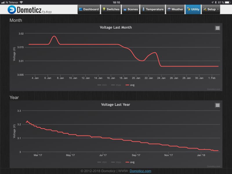
-
Hello, I placed an order through the openhardware.io website with Itead last night.
They came back this morning with a ticket saying :
Your gerber file: 571bf156249971713bb044ea.zip (Normalized Name:A100151928AN_A2AGLF002A.zip) in the order #100151928 is rejected.
The reason is:
The Gerber file doesn't have outline layer , please add it and re-upload the new file , thank you.
Can you please assist as I don't really want to cancel my order.
Thanks in advance
Glenn -
Hi,
This board has an ICSP header. Does it mean that I can use it to burn the bootloader in a new ATMega328 chip?
I've been trying to do burn the minicore in a board with all the required capacitors and resistor but without the NRF, but without success...
Any idea?Thanks,