π¬ Sensebender Gateway
-
@tbowmo
Hi Thomas, Github did have the correct schematic, my remark was based on the schematic on OpenHardware.io (which is now also updated).But my question remains: when using the flash memory, what do you normally do with WP and HOLD ? Should they be pulled up or down ?
-
Depends on if they are active high, or active low.. In this case they where active low, so it actually was an error in the schematics, as it will writeprotect the flash chip.
@tekka please be aware of this, when you try to use the external flash in the bootloader on the dev board that I sent you..
-
@tbowmo
Thanks, in my case they are also active low, so I pull them to VCC.
-
Actually I think that it's more or less an industry standard, that they are active low, Must have had a brain meltdown when I made the schematics back then
-
It seems that the CMSIS is a Cortex communication protocol, so all cortex debuggers should use that protocol?
Are you sure that the st link, doesn't support it?
-
@tbowmo: thx for reply. Yes I have understood the same thing, so it should work... I will try with my stlink (st brand) asap I will receive my pcb.
Talking about stlink, I have just ordered this, very curious.. http://www.aliexpress.com/item/Free-shipping-1pcs-mini-ST-LINK-V2-ST-LINK-STLINK-STM8-STM32-emulator-download-super-protection/32600512506.html?spm=2114.01010208.3.1.1O5urT&ws_ab_test=searchweb201556_9,searchweb201602_1_505_506_503_504_10034_10020_502_10001_10002_10017_10010_10005_10006_10011_10003_10021_10004_10022_10009_10008_10018_10019,searchweb201603_3&btsid=0dfc1060-5064-466c-8071-ac0bab24a988
seriously??so cheap compared to some tools..if it can do the job, could be interesting!
There is also the nice IBDAP, cheap alternative to ice :
https://www.adafruit.com/products/2764
maybe you already know, I have not tested this yet, but seems very simple/useful tool:https://github.com/ataradov/edbg
-
@scalz
That is cheap.. Perhaps I should buy one, just for the fun of it, and try it outI have my jtagice3 though, and it's working fine.. (Even though they don't have the correct cortex-m0 debug port pin layout..)
-
I've been using those cheap $3 ST-Link adapters for flashing ARM cortex chips with OpenOCD, using SWD pins. They're fantastic and work very well.
-
i really like this idea, i'm getting a bit tierd of having the mysensors gateway connected through a breadboard.
how far is it? i saw your comment that it is almost ready for last prototype, is this board fully functional?
Plus, will it be able to act as a Serial/Ethernet/MQTT gateway? or only 1 of these?And if it is ready, is there a place to order them, or just send the files to a PCB company?
-
I'm still waiting for the last prototype pcb's to arrive.
Depending on the sketch you load it with, it can be a serial, ethernet or MQTT gateway. It has native USB in the atsam, and a connector for a w5100 module.
Besides that it will have SD card for local storage of sensor data, so it could in theory operate without a controller at all..
-
@tbowmo Can you give some details about the final dimensions on the board? I want to start the woodworking on the casing for my current gateway. But I'll make sure your prototype fits in as well.
I can't wait 'till this one goes to production. Great work, I'm impressed.
-
The base board is 5x5 cm, but if you use nrf modules they will protrude over the edge of the PCB. Rfm69 is soldered to the bottom so they won't add to the dimensions. W5100 will probably make the base a few mm wider and longer (depending on the module..).
Design files are available at GH, so you can check the dimensions yourself
-
@tbowmo Thanx for your fast reply. It's a great size. I'll create a mockup of it with cardboard. It'll give me a better visualization when I make the housing. Just a final question. I'm guessing I won't be able to stick an Arduino ethernet shield on it right?
-
the GW is not the same dimensions as arduino, so Arduino shields would not fit
A mini w5100 board like this would fit..
Also, see this "old" forum post about the GW device, there is some conceptual pictures of how it would look like with nrf and w5100 attached.
-
Received a new prototype from dirtypcbs the other day
I have only come to the point where the SD Card reader is mounted, as I wanted to try the mechanics out
Currently I'm lacking time for finishing it within the next 2-3 weeks.. If someone knows how to slow down time around you, without being slowed down yourself, please tell me how to achieve it (Too many high priority tasks at the moment..)
-
Great design @tbowmo. Very interesting indeed.
I have some questions and suggestions if you don't mind.Will this support the use of the amplified version of the nrf24l01+ (NRF24L01* + PA + LNA). It uses a little more power than the non aplified version so It's even more sensirtive to power supply noise.
EDIT: In the schematic, upper left corner, in the ATSHA204 module it seems you have forgotten to add the SDA pin conection.
EDIT2: Haven't you thought in adding a battery charger module such as the TP4056. It would be nice to have this board woarking as its own UPS. Having the battery connected in the battery connector without something keeping the battery charged doesn't have much sense to me.
Regards!
-
It should have enough juice in the regulator to support an pa/lna enabled nrf24l01. I havent got one myself, so it's not "validated" yet.
The idea with the battery, is that it is only to keep the rtc alive in the atsam, and if you look at the schematics, then it's only the cpu that can be powered by battery. A coin cell battery should be enough. (I couldn't make room for a battery holder so that's why it just became a 2 pin header
The atsha204 is validated on the board, so it's working If you look at the schematic, SDA pin on the atsha204 is labeled "SECURITY", pin 20 on the cpu is also labeled SECURITY, so these are connected.
-
Thanks @tbowmo. Now it's all clear.
What tests do you think are remaining in order to have the board fully tested and ready to production environement?
Regards!
-
The only thing missing is the Ethernet module at the moment, it has been working on an earlier board, but can't get it working right now.
I'm almost at point where I will let our partner in China do their initial prototype spin, to evaluate production.
-
@tbowmo
In the series 12 Monkeys a scientist developed injections to slow down time at the quantum level, which allows you to be impervious to time shift. Not sure if it slows down time perception itself though.
-
And ethernet is up!
I think this calls for a couple of pictures of the "thing"
first with ethernet / usb (power) connected.
and without ethernet shield
-
Hi @tbowmo. Congratulations.
Have you identified what caused the trouble?
Regards!
-
@tbowmo Congrats! That piece of hardware looks cool. I am interested to replace my current gateway with such a puppy.
-
It was a software issue.. I had rewritten the hardware definition files almost from scratch, and made a couple of errors that made it fail silently..
Peripheral configuration on SAMD21 is a bit more advanced, than on the old atmega328, as you can configure a specific peripheral (a sercom unit for example) to appear on different pins, depending on MUX setting.. I had made some wrong MUX settings for SERCOM4, which is used for the W5100 module.
-
Great work @tbowmo - cant wait until I can get my hands on one
-
If you come to the meetup in MalmΓΆ, you can see a working prototype
-
Hi @tbowmo .
Would you say that the board is ready for production environement? I am planing in ordering one for my home.
Will you share the sketches for the differente gateways configurations?
Thanks, regards.
-
Hi @tbowmo: Nice project. I have a small question about the W5100 board. The board has a standard mail header connector. If I add a (standard) female header, I don't have enough height to compensate for the height of the RJ45 connector. How did you resolve that? Did you use a higher female header? I can't make it up from the pictures.
Thanks in advance,
Ralph
-
Sketches would be the standard sketches for different GW options, as distributed with the mysensors core (it's the same sketches for atmega328p based gateways)
@bisschopsr
Actually a really good question I haven't been able to find a header with extra height.. But what I did on my sample, is that the female header is not mounted flush to the PCB, rather it's raised as much as possible above the PCB, and then it is working.I will have to talk with our manufacturing partner in China, and see what they have as options.
-
Any idea when I'm able to order a couple of those? I'm organizing a MySensors master class for visitors of a Fast Data Event me company is holding in September. Would be great if I'd could show and promote this Gateway. I love it.
-
Im talking with the manufacturer, and hopefully we can start a prototype evaluation very soon now. My guess is that we could start shipping within a couple of months from now, if we don't find any mistakes
-
@tbowmo Great news. Also do we have any idea when MySensors 2.0 will be released?
-
We hope to release 2.0 on the MySensors meetup on Saturday.
-
@hek That would be really awe some. Then I can do a MySensors 2.0 master class. Great news. How are you doing my friend?
-
It's been a while since my latest update, but I am moving closer to production of this gateway.
I have received the first production samples from Itead
I have done hardware verification of the board. Everything seems to be ok, so we are very near the goal.
I can't say anything about pricing yet, as Itead haven't given us a price yet. But I hope that we will be able to announce that very soon (tm)
Finally a picture with all the connectors added as well
-
Great work!! Cant wait until i can buy one Will it be possible to buy in low quantities and ready assembled?
-
We are aiming for a similar setup as for the Sensebender Micro, that is Itead is handling the production and shipping, for us. So yes, they will be SMD assembled, where you have to solder in the connectors that you need.
-
@tbowmo - thanks and again great work!
-
Can't wait to get my hands on one of these. Building a new network based on the RF69 and need a working Ethernet gateway.
-
@tbowmo please let us know when you are ready - I think this GW will be a hit. It is super small compare to mine. Though, mine is based on Mega 2560 + Ethernet shield
-
We are still waiting for price negotiations with itead.
So currently I don't have an eta of the device
-
Did you already try the W5100/RFM69 combo on the production samples?
-
A good question, I think that I have tried both at the same time.. At least I know, that the W5100 and rfm69 is working separately, and they are using separate hardware SPI ports, so they should also work combined.
-
HI @tbowmo
I am developing a similar GW board with a different SAMD chip.
Just one silly question. Could you point me in the right direction regarding which files are the ones that need to be modified so as to tell the compiler that W5100 will be connected at SERCOM1 and RFM69 at SERCOM2 for example.
Thanks, regards.
-
Spi ports are controlled in variant.cpp / variant.h files in the mysensors GW board files.
-
Sorry @tbowmo. I can't find those files in mysensors library. Are those files included or will be included with the release of your GW?
thanks
-
As said they are located in the board variant files. They are in their own repository.
Look here https://github.com/mysensors/ArduinoBoards
And here https://github.com/mysensors/ArduinoHwSAMD
The first is just an installation repository, it contains zipped files from the last one.
-
Any news on availability and pricing from itead?
-
Unfortunately not. I have asked itead studio for a price several times, but it seems that they only have one person who can do the calculations, and he is overloaded with tasks. I hope that we can have something very soon though.
-
This gateway will only run with ethernet and USB? Is there a plan to integrate an ESP for WLAN connection?
-
ESP can be programmed via arduino studio directly, and so you don't need an extra application processor to run mysensors. That is why I dropped support for ESP early on in the project (I had it in there in the first drafts of the schematics)
-
@tbowmo is there something we others can do to make itead studio handle your request faster? Mail them or something?
-
I don't think so, @hek has already pushed the person responsible for the calculations a couple of times via skype.. I do not know what is happening out there (one of the disadvantages of having manufacturers so far away, you can't just stop by to see what they are up to)
-
@tbowmo @hek Would you guys maybe willing to try any other company? There are multiple PCB manufacturers in Hong Kong. My personal experience with Itead is mixed. Their support is extremely poor - It looks like one person responsible for supporting multiple products. They are cheap, but struggling with fast expansion launching their own IOT products (Sonoff).
-
we have looked at a couple of other manufacturers in China / Hong Kong area.. But found (back then) that Itead was the best solution, as they would handle manufacturing, stock, and shipment for us, and pay us a commission of the sale which makes it extremely easy for us to handle product launches
With the other manufacturers we had to buy 100/200 units, and handle stock / shipment ourselves, and with the limited time for the project (as most of us have families and daytime jobs to take care of, besides of bringing new products into the world), this is not a feasible solution..
My contact person at Itead, promised that she would get the quotation guy to answer me today. So let's see what happens
-
I'm not sure. But I think I read somewhere that the manufacturers in china are closed due to holiday.... At least I think I read that on aliexpress.
-
I think that they just returned from holiday. I was at least in contact with itead the other dah, where I received a couple of mails from my contact person. Just need the quotation guy to wake up from his hibernation mode
-
Got this from one eBay seller when I asked why my order was delayed.
"I am so sorry for the dalay. because of National Day in China, we were from 30th sep to 5th October on vacation."
-
@tbowmo Hi! Very cool design, I especially like using of ARM microcontrollers. I have a lot of projects with SAMD20, and I want to give you a little advice for your future revision of your "Mysensors Gatevay". When I had problems with my devices work (there were crashes and hangs) I found the circuit of evaluation board called "SAM D20 Xplained Pro". After examining this circuit I saw that they apply more capacitors in the power supply than I. And I thought that use just one capacitor 100 nF not enough. So, I corrected the filtering circuit in my devices and everything worked perfectly. Below I'm showing the filtering scheme:
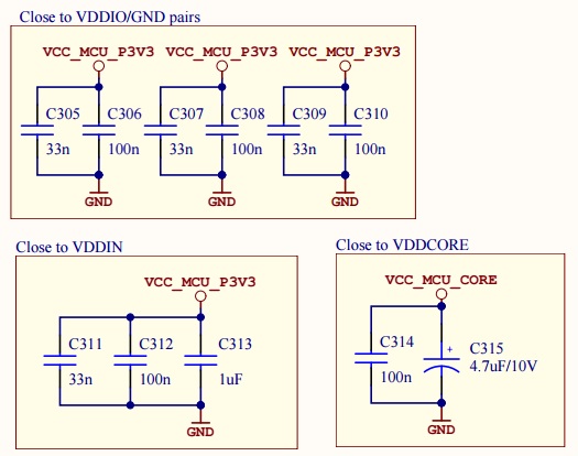
-
Thanks for the tip.. I took heavy inspiration from the arduino zero, which only has 100nF capacitors for decoupling.
I haven't seen any problems with stability on the prototype GW's that I have build, we also have 5 production sample GW's out in the wild, at a couple of the core group members, and I have not heard any problems from them either.
Anyways, I have noted it, and will take it into consideration if I/we decide to do a new revision of the schematic / layout.
-
@tbowmo said:
@kalina
I haven't seen any problems with stability on the prototype GW's that I have build...Of course, your device may work perfectly without additional capacitors. This is just my experience.
In my devices there are large number of impulse noises, because they contain FPGA... and one more interesting thing, I have compared two datasheets on SAMD20 and noticed that in new revision they have increased the VDDCORE capacitor from 100 nF to 1 uF
-
Is there any news about selling this PCB ?
-
As mentioned in the latest announcement, pre-sales have just opened up over at itead.cc, so head over there to order it
-
Is there an option for a WiFi connection?
-
You can have mysensors running natively on the esp8266, so we decided not to support WiFi on this gateway device.
-
I find it on Itead but no announcement on mysensors.org.
-
@Fabien do you mean the gateway? It is available on https://www.mysensors.org/hardware/sensebender-gateway
Where did you expect to find it? Maybe we need to update some documentation with a link?
-
Which exact RFM69 is the footprint for? Cause it says "RFM69HCW" in some places, and "RFM69HW" in others. The footprint looks a lot like HW (https://c1.staticflickr.com/1/563/20328459340_62fa380554_b.jpg).
-
@hek : strange, this afternoon I can't see it on "news history" !
-
I did some updates this afternoon (among them the news section).
We will continue updating the Sensebender Gateway article during the coming days.
-
Oh and another question, since I've never ordered anything from ITEAD before, how do they declare the customs value? Is it safe to order more than one gateway or should I order them one by one to be on the safe side? I'm talking about "SF E-Parcel" or "Registered Air Mail" of course, not TNT or DHL.
-
@bjornhallberg, I don't remember what the value was set to on the latest package from them.
Suggest you contact them here:
https://www.itead.cc/contact-us
-
@bjornhallberg they declare a very low customs value (for my last order only 12x0.89β¬ ...)
I juste order the gateway today.
-
I also just order my gateway
-
This is on my most wanted purchase list now.
FYI, I noticed the spelling of "Sensebender" is "Sensbender" for this gateway on openhardware.io, so you're breaking your brand name. Would it be possible to amend it? If you try to search for it with the original spelling you only find the two sensor Sensebenders.
-
Opps! Thanks for reporting @martinhjelmare.
-
This has been on my watch list for some time. Excellent work guys - I placed an order and looking forward upgrading my gateway.
-
Is this device capable of being a gateway for both nRF24L01+ radio and the Hope RF RFM69HCW radio simultaneously ?
I have some nRF24 nodes and see a lot of new goodies equiped with the RFM69 radio. One gateway to serve both would be excellent !
-
No, only one radio type or rs485 is possible at the moment.
-
The hardware supports both NRF and RFM69 at the same time, they share the same SPI bus, but has separate chip select lines etc.
Unfortunately the MySensors library doesn't support multiple transports, so this time it's the software that limits things.
-
Yes ! Itead send me the gateway today
-
@Fabien said in Sensebender Gateway:
Yes ! Itead send me the gateway today
I have got mine today. Very quick
-
@tbowmo
The fact, that MySensors doesn't support more then one radio, was the reason for me not to order the sensebender gateway.I am working on a gatewayβcontroller based on an arduino due, which supports at least up to 3 serial gateways via hardware serial. It handles ID and time (synced with ntp) requests and does pub/sub to mqtt with readable topics.(inspired by the old mqtt client gateway)
-
@FotoFieber this is a software limitation. Hardware wise I do not see why Sensebender GW cannot handle two (nrf24l01+ and rfm69/rfm95) GWs at the same time
-
@alexsh1
The question is: will the software restriction be solved? If not, I do not care if it is a software or a hardware restriction.
-
Well, you need to hack the core anyways, if you want to accomplish your goal.
You could also help out with the core development, so we can get support for multiple transport on one gateway
-
@tbowmo
No, I don't have to hack the core. I use the serial API. From an architectural point of view, I don't see the need to change anything in MySensors. A serial controller can be built for under 20β¬ Including the radio. Why should I add complexity to support more than one radio support with one cpu in MySensors, if I can have the functipnality with the abstraction layer of the serial API? Please keep MySensors s simple as possible.
-
@FotoFieber simple for who? Simplicity also involve maintenance and code complexity. What about testability and regression testing? Nobody gets paid for maintaining mysensors.
-
But you ditched the sensebender Gateway, as it doesn't support multiple radios at the same time? Now you are saying that you would keep it as one radio per gateway?
This doesn't make sense
-
@tbowmo
Maybe the design of the sensebender gateway doesn't make sense to my architectural viewpoint....
-
@FotoFieber This is a question for the MySensors dev team. Sensebender can handle both radios. Currently, there is a software restriction.
-
@FotoFieber No, you do have to hack the core if you want both radios to be handled properly, i.e. to handle message queues with corresponding radios. For example, sending a message is done via rfm69 only and not via nrf24l01+
-
The architecture we use would place this kind of situation to the controller to solve. One gw per network. So one gw for nrf and one for rfm.
HW is cheap, and library should be kept simple.
-
@Anticimex
One gateway per radio, that is what I think is best.What I try to do, is to implement a controller with arduino due for up to three serial gateways. If there would be a solution for ethernet&rfm69 I may not have invested time in this.
-
Well sensebender GW supports rfm69 with ethernet
-
@tbowmo
Yes, that is really nice.My other goal was to have a new MQTTClientGateway, as it existed with MySensors 1.1 (which is not only a gateway, but a controller too). It would have been really painful to add it to MySensors 2.1.x, as I would have to patch core files. It is much easier, to throw hardware at it.
-
@tbowmo More practical question. I have received the GW and it already has MySensors 2.1.0 software. Excellent service by Itead. Can you please help me how to map LEDs in the GW sketch? I can see that they are connected to pins 38, 41, 42, 39, 40 as LED1, LED2, LED3, LED4 and LED5. Thanks
-
you should be able to use LED_BLUE, LED_GREEN etc. defines (or even just LED_1, LED_2..) in your sketch, to access the different LED's on board the gateway. That is, if you are using the SenseBender GW hardware support files in arduino (installation instructions are here https://github.com/mysensors/ArduinoBoards)
Also, look at the board definition files, located here https://github.com/mysensors/ArduinoHwSAMD/blob/master/variants/mysensors_gw/variant.cpp
and here https://github.com/mysensors/ArduinoHwSAMD/blob/master/variants/mysensors_gw/variant.h
-
@tbowmo Excellent links, many thanks. BTW the board is working with the standard arduino samd, the problem I suppose comes with things LEDs.
-
You might be able to compile with the standard arduino zero BSP files. But the IO mapping is not the same at all.. I have swapped some pins to make routing a bit easier. Also the SPI channels are configured a bit differently than the standard arduino, if I remember right. So I will advise to use the mysensors gateway BSP files..