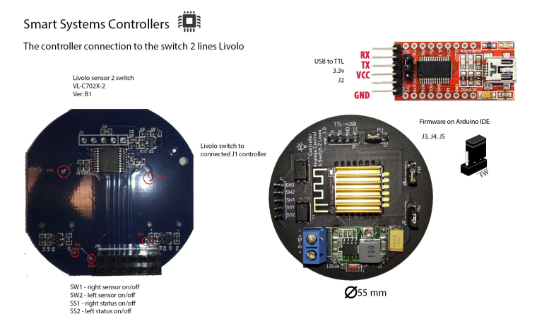
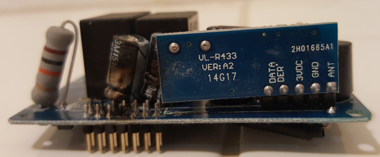
livolo Glass Panel Touch Light Wall Switch + arduino 433Mhz
-
@Nca78 Very interisting if the prices are the same and the design! You have a buyer :P Hope you ship to Portugal eheh I will be waiting for your solution for EU. Cause honestly i did not wanted to make too complicated adaptations on the circuit.
@Hugo-Pereira said:
@Nca78 Very interisting if the prices are the same and the design! You have a buyer :P Hope you ship to Portugal eheh I will be waiting for your solution for EU. Cause honestly i did not wanted to make too complicated adaptations on the circuit.
I think you misunderstood :P
I'm making only the PCB (electronic board on which to solder the components). So you still need to buy Livolo switches (with no radio) and then get my PCB done and solder components on it. Then replace the touch PCB from Livolo switch with it.
It won't be very expensive (about 5-6$ of parts per switch I think) but there's some work to do :P -
@Hugo-Pereira said:
@Nca78 Very interisting if the prices are the same and the design! You have a buyer :P Hope you ship to Portugal eheh I will be waiting for your solution for EU. Cause honestly i did not wanted to make too complicated adaptations on the circuit.
I think you misunderstood :P
I'm making only the PCB (electronic board on which to solder the components). So you still need to buy Livolo switches (with no radio) and then get my PCB done and solder components on it. Then replace the touch PCB from Livolo switch with it.
It won't be very expensive (about 5-6$ of parts per switch I think) but there's some work to do :PHi, I'm working on this one too. This Livolo stuff captured my attention a long time ago as I needed an in wall solution for controlling the lights(without using batteries and such). I wanted this to be integrated with the existing infrastructure also(the existing house electrical wiring for lights). I studied the power supply part before the Livolo switches era as I wanted to make one of my own but in the end it seemed not so an easy task because of the series circuit( to take power from the live wire only). Anyways if the power board from the existing Livolo switches will be capable of delivering the required power it will be really awesome(as the non radio switch is really cheap
).
In my case I'm using the rfm69 module(the CW variant as it's more compact) which requires a little bit more current(45 mA or so). I don't want to use the existing 3V line which the Livolo power board has because as I've seen from this thread pictures and schematics it uses a low current voltage regulator(30mA max or so from my investigations). This is fine for the nrf24l01 low power variant but for RFM69 it isn't. So currently I'm working on identifying the 12V line as my design uses a buck converter to get it as low as 3.0-3.3V.The project and progress is posted here: https://www.openhardware.io/view/306/Livolo-EU-switch-Mysensors-integration. Depending on my free time I will continue to work on it but I don't know when it will be finished.
Keep up the good work and congrats to the Mysensors creators for this wonderful project.
-
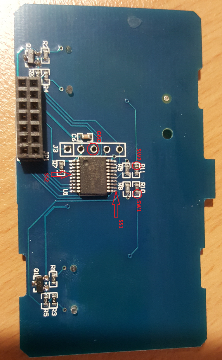
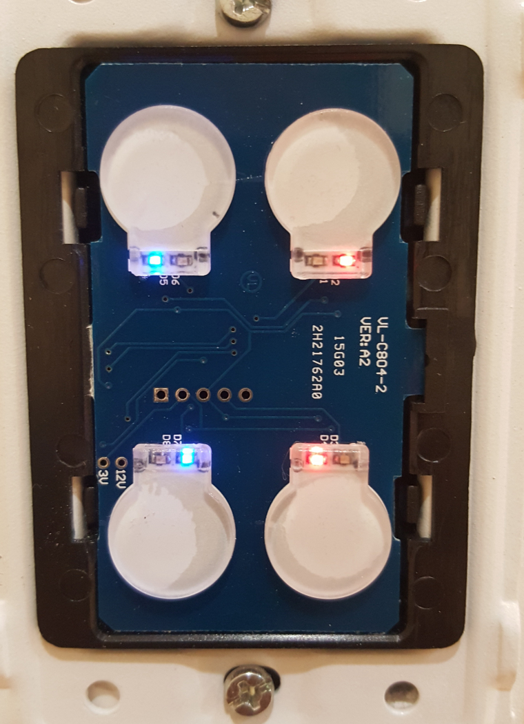
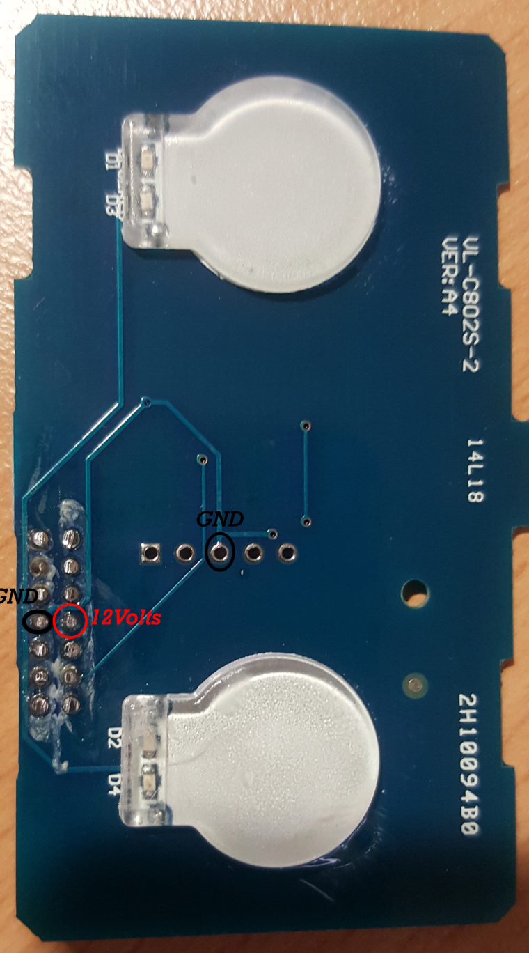
Hello, on the US/AU version there is a 12V pin on the 2*7 connector. It's opposite the GND

-
сегодня доделал Livolo+esp8266 пришлось помучаться с программой и схемой питания но все заработало[0_1485259118390_livolo_esp.mp4](Uploading 100%)
-
сегодня доделал Livolo+esp8266 пришлось помучаться с программой и схемой питания но все заработало[0_1485259118390_livolo_esp.mp4](Uploading 100%)
@DJONvl said in livolo Glass Panel Touch Light Wall Switch + arduino 433Mhz:
сегодня доделал Livolo+esp8266 пришлось помучаться с программой и схемой питания но все заработало[0_1485259118390_livolo_esp.mp4](Uploading 100%)
-
@DJONvl said in livolo Glass Panel Touch Light Wall Switch + arduino 433Mhz:
сегодня доделал Livolo+esp8266 пришлось помучаться с программой и схемой питания но все заработало[0_1485259118390_livolo_esp.mp4](Uploading 100%)
Yesss @DJONvl . Thats is !!!! .
You got it !!!Please can you post all the details about how you are do it ??
How you are managed to achieve enough power from Livolo ??
How you wired the esp8266 and where on the livolo switch ??
You can post the schematic ??
Please, all details you can...
Regards
-
@DJONvl said in livolo Glass Panel Touch Light Wall Switch + arduino 433Mhz:
сегодня доделал Livolo+esp8266 пришлось помучаться с программой и схемой питания но все заработало[0_1485259118390_livolo_esp.mp4](Uploading 100%)
-
-
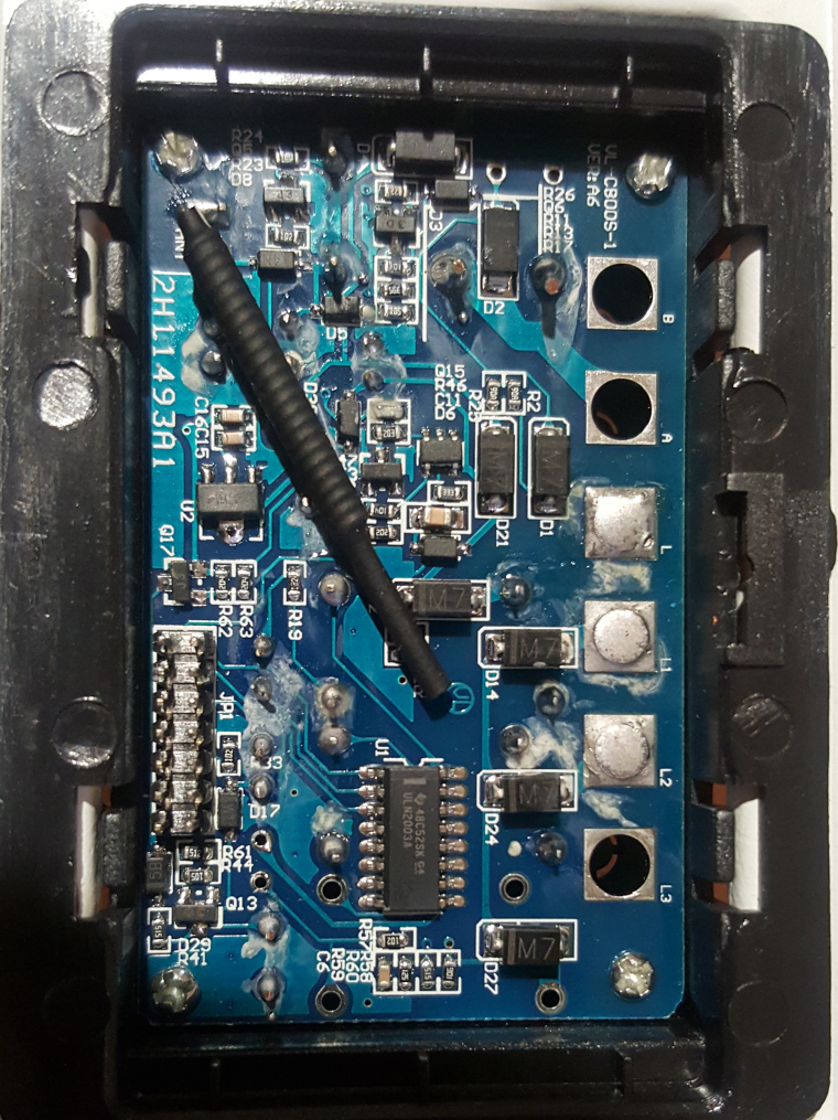
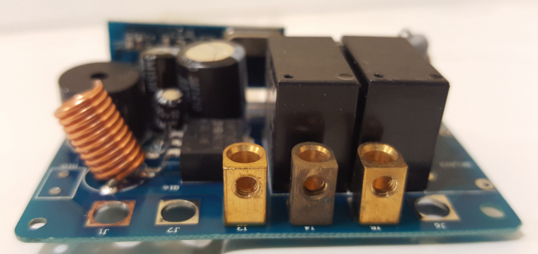
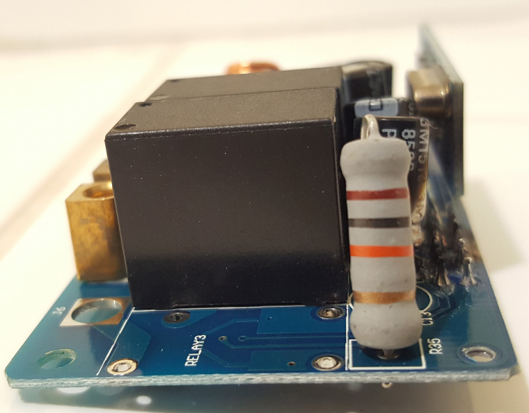
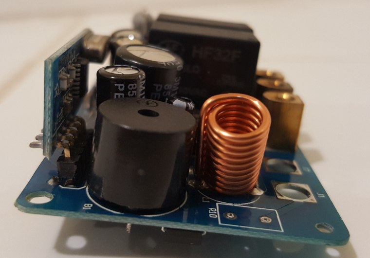
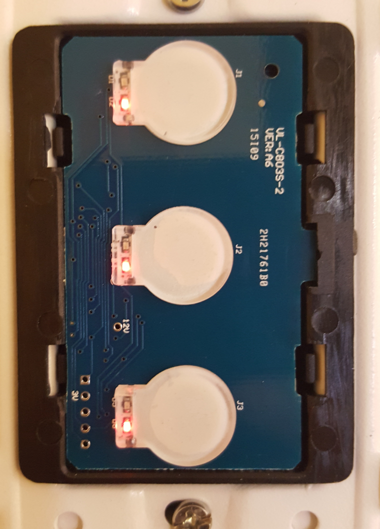
For power, I found these on the board. The 12V accutally read 14.86V for the two Switch gang and 14.10V for the 1 gang switch. This was me using the multimeter connecting with ground.
1 Gang Switch even have indication of the board
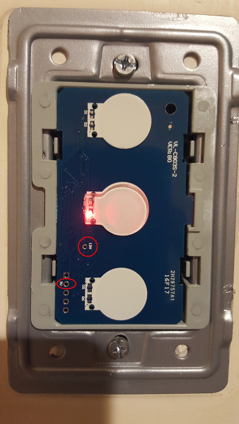
2 Gang Switch
-
@Markhill for switching on/off the relays it's not that simple. On the 'main' board there is a decoder connected to 3 pins or the MCU and on the 2x7 header.
Check in one of my messages above for the pin out on the header. -
@Markhill it cannot work, this board needs external power because the ESP8266 he is using is too power hungry, the switch cannot provide enough power. And this board is sized for EU switch it will not work with US or US/AU switch.
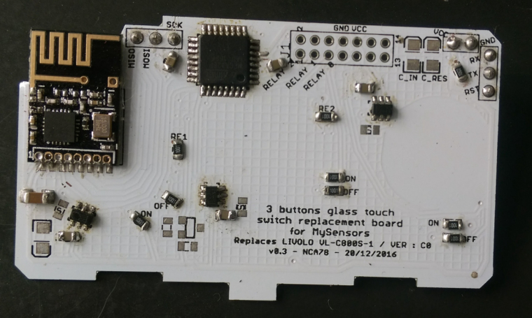
I'm working on 3 buttons and 4 buttons version with atmega and nrf24, power from the swith is enough so it's just a plug&play replacement. I'm testing the 3 buttons switch at the moment (same layout than 1 button in which only the center button is connected). It will be cheaper than 15$ if you solder it yourself, if you don't want to do smd soldering we can probably find a solution for pre-assembled boards.
-
@Markhill it cannot work, this board needs external power because the ESP8266 he is using is too power hungry, the switch cannot provide enough power. And this board is sized for EU switch it will not work with US or US/AU switch.
I'm working on 3 buttons and 4 buttons version with atmega and nrf24, power from the swith is enough so it's just a plug&play replacement. I'm testing the 3 buttons switch at the moment (same layout than 1 button in which only the center button is connected). It will be cheaper than 15$ if you solder it yourself, if you don't want to do smd soldering we can probably find a solution for pre-assembled boards.
@Nca78 I'm in. Plug and play, same size, no external power and cheaper too. When will it be ready?
Btw, your board will be able fit on a 3 buttons and 4 buttons too right? I got them.
Will it provide status feed back, control remotely on phone app or ioBroker and is there any coding required?
-
Keep us updated on your development, i'm working on a double relay module for lighting but i doubt its going to fit inside of a single gang wall box.
-
@Nca78 I'm in. Plug and play, same size, no external power and cheaper too. When will it be ready?
Btw, your board will be able fit on a 3 buttons and 4 buttons too right? I got them.
Will it provide status feed back, control remotely on phone app or ioBroker and is there any coding required?
@Markhill I have made 2 boards, one for 1/3 buttons, one for 4 buttons.
It will be a MySensors actuator so yes status feedback etc.I'll make a script for basic switch function and probably a few extra things two. I'm planning to use 3 button switches in my home to command 2 light circuits with the top and bottom buttons, and AC with center button (not using the relay). I have included 2 extra leds on center button for that, to select different modes of AC.
The 4 buttons version uses sx1509 extender to have more advanced feedback like breathing/flashing LEDs but it's probably not in a final form yet, it will take more time to be ready.
-
@Markhill I have made 2 boards, one for 1/3 buttons, one for 4 buttons.
It will be a MySensors actuator so yes status feedback etc.I'll make a script for basic switch function and probably a few extra things two. I'm planning to use 3 button switches in my home to command 2 light circuits with the top and bottom buttons, and AC with center button (not using the relay). I have included 2 extra leds on center button for that, to select different modes of AC.
The 4 buttons version uses sx1509 extender to have more advanced feedback like breathing/flashing LEDs but it's probably not in a final form yet, it will take more time to be ready.
@Nca78 said in livolo Glass Panel Touch Light Wall Switch + arduino 433Mhz:
buttons version uses sx1509 extender to have more advanced feedback like breathing/flashing LEDs but it's probably not in a final form y
Can you send me the 1/3 buttons so I can test it?
The switch I use at home is a 3 gang 2 way. That is one light control by two switches. Will your board still work with these?
Thanks.
-
@Nca78 said in livolo Glass Panel Touch Light Wall Switch + arduino 433Mhz:
buttons version uses sx1509 extender to have more advanced feedback like breathing/flashing LEDs but it's probably not in a final form y
Can you send me the 1/3 buttons so I can test it?
The switch I use at home is a 3 gang 2 way. That is one light control by two switches. Will your board still work with these?
Thanks.
I don't know about the 2 way switches so don't have one to check. But in my home I will just connect one side to a normal switch and use switch on the other side as radio switch only without the relay.
You want a 1/3 switch PCB ? Where do you live ?
-
Do you guys happen to know what the capacitive touch button part is called? I'm trying to look for some of these on the internet and getting nothing relevant coming up. Just the little glass/acrylic parts of the livolo switches that recognise your touch.
MySensors 2.1.1
Controller - OpenHAB (Virtual Machine)
Gateway - Arduino Mega MQTT Gateway W5100