💬 NRF2RFM69
-
@Markus. You have an RF issue. Typically for nrf24l01+ I'd use a different power supply or a different module.
Are you sure both modules are set to the same channel and frequency? What antennas are you using?
Do you have HW modules? -
@alexsh1 I use at the Moment RFm69W 868 modules not NRF. Because the RFMs are mounted on the NRF connector on an EasyPCB. I use at the Moment single wire antennas with a lenght of 8,3 cm.
-
@alexsh1 should be, becaus ist not defined explicit in the Sketch. By Default in the MYS Lib 2.2 dev is it 868 mhz. And when i try to define the frequency in the Sketch. Like
#define MY_RFM69_FREQUENCY RF69_868MHZ
I get the error message.'RF69_868MHZ' was not declared in this scope -
@alexsh1 should be, becaus ist not defined explicit in the Sketch. By Default in the MYS Lib 2.2 dev is it 868 mhz. And when i try to define the frequency in the Sketch. Like
#define MY_RFM69_FREQUENCY RF69_868MHZ
I get the error message.'RF69_868MHZ' was not declared in this scope -
@mfalkvidd you are right... Ist now added in the GW and node Sketch, but still the same Problem.
-
I think at the end will it be a power problem. It seems that the sensor node powered with 2x AA cells can not handle the Radio on TX/RX. The same on the Gateway site which is also a Easy PBB powered fom the FTDI Connector connected to USB. The question now is how can i fix this power Problems ? Or more, how can i make sure that this is definitly not the reason.
-
@gohan 10uF electrolyt cap direct on the radios already tierd beside the 4,7uF on the Radio socket.
@gohan ohhhh helllll... its working.. As usual.. the Problem was infront of the Monitor... :-) So, two Problems. the first mistake i did was to use a HW module as Gateway. The power source was a FTDI adaptor which has only max Output current of 50mA (HW module Needs 120mA Minimum). The result was randomly reboot of the Gateway. The second and main Problem was the Jumper of the IRQ on the Easy PCB boards. I checked only the domumentation and there is the Jumper wrong descriped. So i placed the Jumper wrong. I have corrected this now on my two test boards and use a W module on the Gateway.. now its working :-)
Many thanks for all the Patience... :-) -
@Markus. said in 💬 NRF2RFM69:
I checked only the domumentation and there is the Jumper wrong descriped
Where is it wrong described?
@gohan the arrow goes to the Jumper close to the cap on the NRF socket.
[link text]https://www.openhardware.io/view/4/EasyNewbie-PCB-for-MySensors(link url)
But the other Jumper isthe right one . Well, could be also wrong interpreted frommy site, however ist now working and the range is also fine so far... -
you are right, the picture has an error, but the pcb has the right labels. Maybe @sundberg84 may fix the picture :)
-
@Markus. Sorry, this is because it was changed from Rev 8 to Rev 9 and the location of the IRQ jumper is changed. I will try to update to REV 9 pictures only.
-
@tbowmo said in 💬 NRF2RFM69:
I've added the panel design to dirtypcb's store.. So just order it from the following link
http://dirtypcbs.com/view.php?share=16378&accesskey=4e199dccdf623eab0c90fddbc4786f80
I ordered PCBs from dirtypcbs via the link above. But just now I got this message from dirtypcb:
"Problems Drill holes don't match with the solder pads."
Do you know why?Thanks for your help!
-
@gohan But then I guess you didn't use the panel version?
From what I can see it looks like the drill file in the panel version is missing the drill holes on the board itself. It looks like it only contains the drill holes between the cards? I am not sure, and has little experience with drill files and pcb design, but it looks like this when I open the drill file (and the profile layer, .gml-file) in gerbview in kicad:
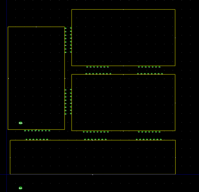
From what I can see the drill holes on the boards itself is missing, but I guess there are others that have ordered this panel version from dirtypcbs, so I find it strange that there should be an error.