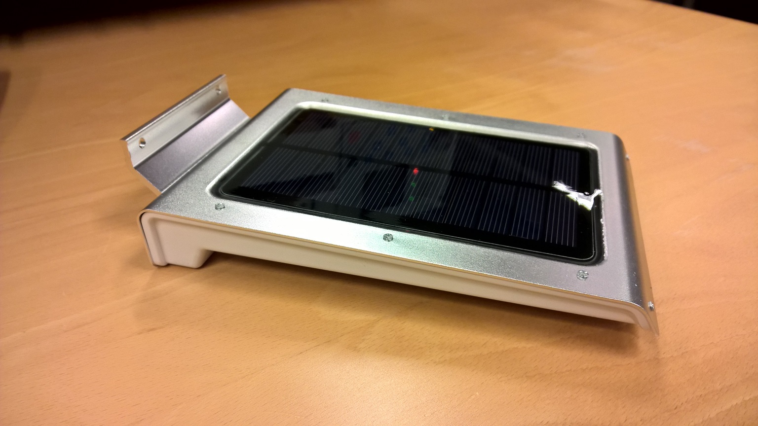
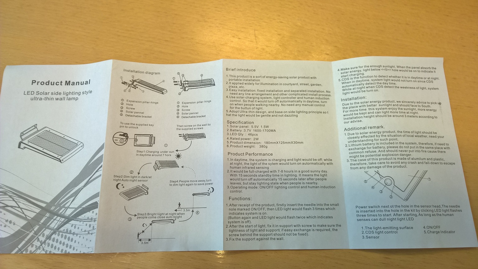
Chinese Solar Lipo powered PIR led lamp.
-
higher math for me...
Great...Can you use the motion seperate from the liight?
And can u use the light with a switch option? [ i will turn on the light when there is motion.. ]
Or is the light switching only on lux?Domoticz, with a lot of working hardware, include mysensors :-)
OpenPLI, RuneAudio, Solarmeter, etc......Not a great builder of software and hardware, more a user...
Only i try to do my best :-( -
higher math for me...
Great...Can you use the motion seperate from the liight?
And can u use the light with a switch option? [ i will turn on the light when there is motion.. ]
Or is the light switching only on lux?@GertSanders thanks, you have motivated my research
@Dylano the purpose of this project was exactly what you have asked.
The lamp is now mysensors aware.
Every task can be operated separately.-
When there is dark, the trigger is send, when the sun shines, the trigger is send. (transistor as switch). In scetch i use it as magnet switch part of code. When trigger is received (can wake up arduino), than you decide with controller what you want to do .
-
PIR acts as classic PIR sensor and can also be used as trigger. (can wake up arduino), than you decide with controller what you want to do.
-
The Lamp have two phases and can be controlled with controller (i control it over mqtt for now)
-
phase one is dimmed light (relay 1)
-
phase two is high bright light (relay 2)
Below is code that works for now. I wil improve it in next few days
// Enable debug prints #define MY_DEBUG #define MY_NODE_ID 11 // Enable and select radio type attached #define MY_RADIO_NRF24 //#define MY_RADIO_RFM69 #include <SPI.h> #include <MySensor.h> #include <Bounce2.h> //unsigned long SLEEP_TIME = 120000; // Sleep time between reports (in milliseconds) #define DIGITAL_INPUT_SENSOR 2 // The digital input you attached your motion sensor. (Only 2 and 3 generates interrupt!) //#define INTERRUPT DIGITAL_INPUT_SENSOR-2 // Usually the interrupt = pin -2 (on uno/nano anyway) #define CHILD_ID 12 // Id of the sensor child boolean lastMotion = false; // Initialize motion message - start MyMessage msg(CHILD_ID, V_TRIPPED); //trigger solar power day on/off -start #define CHILD_ID_SW 5 #define BUTTON_PIN 5 // Arduino Digital I/O pin for button/reed switch Bounce debouncer = Bounce(); int oldValue = -1; // Change to V_LIGHT if you use S_LIGHT in presentation below MyMessage SolarMsg(CHILD_ID_SW, V_TRIPPED); // trigger solar - end #define RELAY_1 3 // Arduino Digital I/O pin number for first relay (second on pin+1 etc) #define NUMBER_OF_RELAYS 2 // Total number of attached relays #define RELAY_ON 1 // GPIO value to write to turn on attached relay #define RELAY_OFF 0 // GPIO value to write to turn off attached relay void setup() { //trigger solar power day on/off - start // Setup the button pinMode(BUTTON_PIN, INPUT); // Activate internal pull-up digitalWrite(BUTTON_PIN, HIGH); // After setting up the button, setup debouncer debouncer.attach(BUTTON_PIN); debouncer.interval(5); //trigger solar - end pinMode(DIGITAL_INPUT_SENSOR, INPUT); // sets the motion sensor digital pin as input for (int sensor = 1, pin = RELAY_1; sensor <= NUMBER_OF_RELAYS; sensor++, pin++) { // Then set relay pins in output mode pinMode(pin, OUTPUT); // Set relay to last known state (using eeprom storage) digitalWrite(pin, loadState(sensor) ? RELAY_ON : RELAY_OFF); } } void presentation() { // Send the sketch version information to the gateway and Controller sendSketchInfo("Motion Sensor and light", "1.0"); // Register all sensors to gw (they will be created as child devices) present(CHILD_ID, S_MOTION); for (int sensor = 1, pin = RELAY_1; sensor <= NUMBER_OF_RELAYS; sensor++, pin++) { // Register all sensors to gw (they will be created as child devices) present(sensor, S_LIGHT); // Register binary input sensor to gw (they will be created as child devices) // You can use S_DOOR, S_MOTION or S_LIGHT here depending on your usage. // If S_LIGHT is used, remember to update variable type you send in. See "msg" above. present(CHILD_ID_SW, S_DOOR); } } void loop() { // Read digital motion value boolean tripped = digitalRead(DIGITAL_INPUT_SENSOR) == HIGH; if (lastMotion != tripped) { Serial.println(tripped); lastMotion = tripped; send(msg.set(tripped ? "1" : "0")); // Send tripped value to gw } // Sleep until interrupt comes in on motion sensor. Send update every two minute. //sleep(INTERRUPT,CHANGE, SLEEP_TIME); //trigger solar power day on/off - start debouncer.update(); // Get the update value int value = debouncer.read(); if (value != oldValue) { // Send in the new value send(SolarMsg.set(value == HIGH ? 1 : 0)); oldValue = value; //trigger solar power day on/off - stop } } void receive(const MyMessage &message) { // We only expect one type of message from controller. But we better check anyway. if (message.type == V_LIGHT) { // Change relay state digitalWrite(message.sensor - 1 + RELAY_1, message.getBool() ? RELAY_ON : RELAY_OFF); // Store state in eeprom saveState(message.sensor, message.getBool()); // Write some debug info Serial.print("Incoming change for sensor:"); Serial.print(message.sensor); Serial.print(", New status: "); Serial.println(message.getBool()); } }``` -
-
mmm i ordered 1...
So i hope i gonna ix this...
It is looking higher mathematicsWill see... when i have time..
Thanks for the sketch!!!
Give it a try in a uno ... -
guess what...
I do have a:
http://www.ebay.com/itm/161885080971?_trksid=p2057872.m2749.l2649&ssPageName=STRK%3AMEBIDX%3AIT
Exact the same board in of this light...
I think i going to try the make this work...Only i do not understand exact the wiring of your example.
Will you please make a list of exact stuff to buy.
And make some more pictures, from the good places..And a thing that i see.
You use D2 from the arduino.
Is that not a one for the radio? -
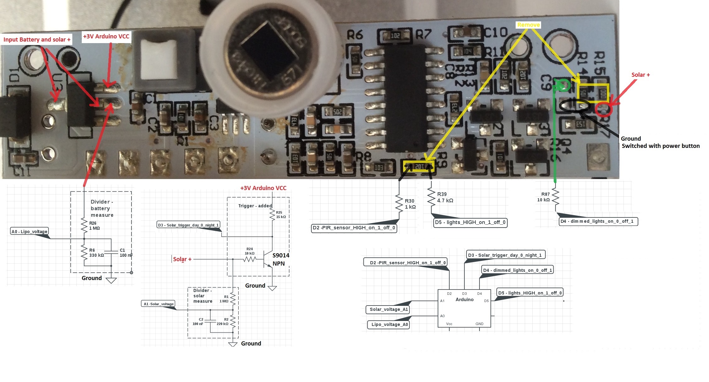
@GertSanders I think i managed to successfully connect arduino with solar lamp.
My prototype is working, and has the following functions:
- Measure battery voltage (when charging it is alway 100% - makes sense)
- Measure solar voltage (can be omitted - but resistor should be there for a transistor to work properly)
- Solar power day/night trigger with transistor as a switch (can be used wake up arduino from sleep)
- PIR sensor (can be used wake up arduino from sleep)
- Lights on/off dimmed brightness
- Lights on/off high brightness ( original resistor R9 -1k was replaced with 4.7k - i think it draws to much current and sometimes hangs arduino)
I will post the code later, but every part works with default "mysensor" examples
How to connect and how to add elements see picture:
-
mmm i ordered 1...
So i hope i gonna ix this...
It is looking higher mathematicsWill see... when i have time..
Thanks for the sketch!!!
Give it a try in a uno ...@Dylano Great to hear that the light has the same board...please post a picture.
My light is still protoype connected together on protoboard - connected to arduino pro mini - i can post only a picture connected elements on protoboard for now.
I am trying to put all together in openhab now.
I will try to make a list of exact elements.
I have free D2 pin on arduino pro mini. -
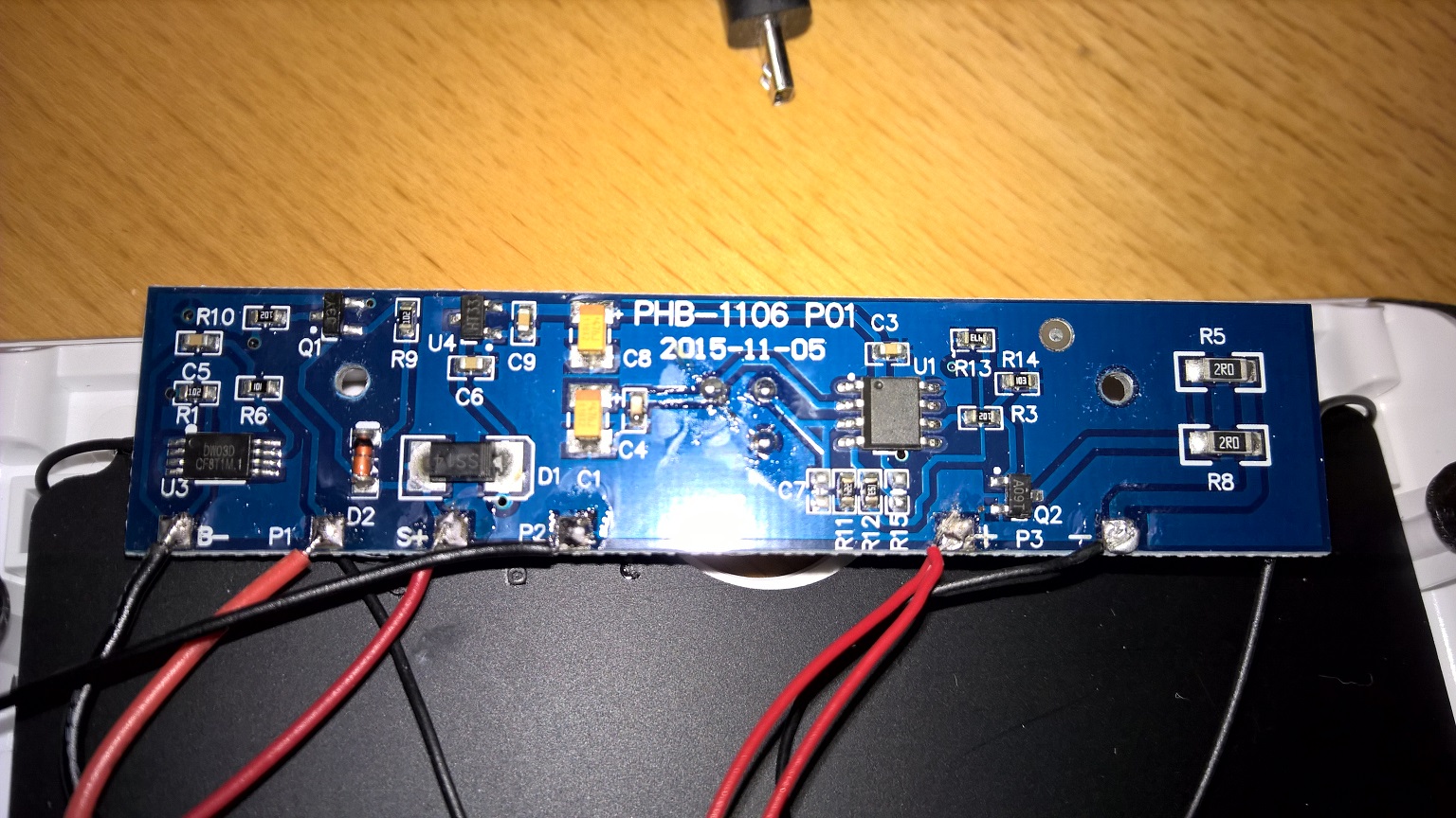
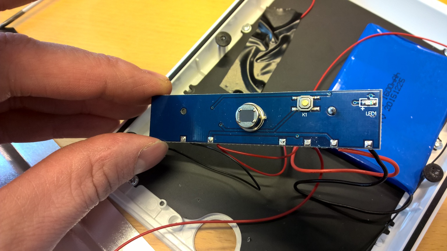
Got myself a similar PIR LED lamp. The functionality seems like it is the same but the circuit board is different.
@korttoma
Nice to see some interest in smart solar lamps :)
It looks like an updated version (at least i like it more from your pictures). Could you post an order link.
I think this one should be even easier to intercept with "mysensors", beacause i see only two transistors and circuit connectios are clearly visible.so lets try to understand the circuit:
-U3 is probably battery protection circuit- Q1 i think is voltage regulator HT33 - to power arduino wih 3.3V (meassure voltage)
- take a photo of PIR sensor from front side (is there any ic elements)?
- U1 - i would guess PIR sensor IC logic - leg 6 (count from dot on IC) should be output (meassure voltage - high 3,3 V when motion detected):
-if it is output from PIR just remove R3 and IC ouput goes over resistor to you arduino input. - the output goes over resistor to Q2
-whats is left - you have to figure out what drives resistor Q1(J3y) : - i gues its driven by solar cell, than collector is connected to resistor R10, resesitor is than connected over board to the other side.......
-
I guess you meant U4 is the 3.3V regulator. I measured it to 3.3V and HT33 should be a regulator. Q1 and Q2 I think are transistors. U3 handles the solar charging. U1 is for the PIR but unfortunately there is no text on the chip. I will get you the link tomorrow but it is quite easy to find on aliexpress.
- Tomas
-
I guess you meant U4 is the 3.3V regulator. I measured it to 3.3V and HT33 should be a regulator. Q1 and Q2 I think are transistors. U3 handles the solar charging. U1 is for the PIR but unfortunately there is no text on the chip. I will get you the link tomorrow but it is quite easy to find on aliexpress.
@korttoma
sorry my typo: you are correct- U4 - HT33 is voltage regulator
- yes Q1 and Q2 are transistors
- U1 - PIR out test - measure voltage between PIN 6 and R3 when PIR is OF and ON. I think this drives Q2 (high brightness / low brightnes)
also take picture of other side of circuit board, beause i think Q1 is conected to R10 and
then further on the other side -
Here is the link to the one I got but it seems like the prize is allot higher now since I paid 23,84$ including shipping -> http://www.aliexpress.com/item/1-Set-1200-Lumens-46-pcs-LED-Solar-Power-Motion-Sensor-Lamp-Ultra-thin-PIR-Outdoor/32354254209.html
Also it took like 10 weeks for it to arrive so maybe another seller would be a better fit.
-
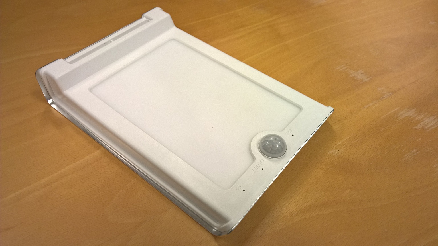
There is not much on the other side of the board, just a status LED, a button to turn it on and the PIR.
-
I'm sorry I did not test the device I just read the manual so I think that yes it has 2 modes for LED brightness.
@korttoma
Don't be sorry.I am not an circuits expert, I just try help you figure things out.
You wil have to test this lamp a little bit.
it looks that Q1 drives U1 active/not active when there is sun, but how/what turns on dimm lights in dark?Did you measure U1 pin 6 when pir active/not active?
-
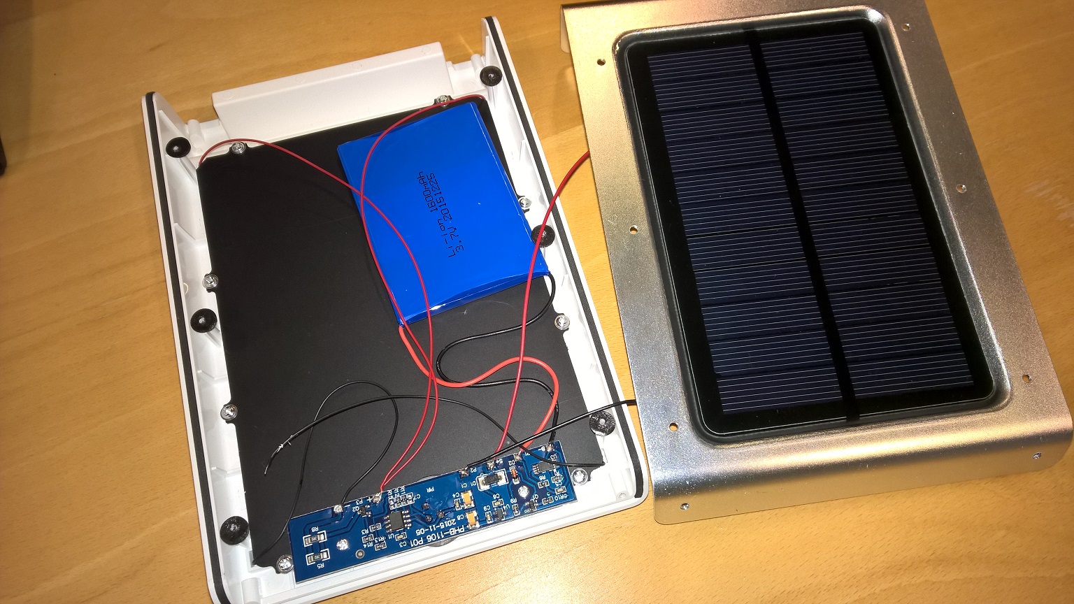
In the application I will use this one I actually do not care so much for the built in PIR and LED, I just see it as a smart enclosure with a solar battery power-supply built in. I will tap in to the 3.3V regulator to power a pro mini that has an external PIR and (LDR) Light sensor. In addition to this I would like to add voltage measurement for the battery. BTW, did you komplette your sketch? I would like to copy the battery voltage sensor part. I will look att figuring out the circuit later, it does not look to complicated.
- Tomas
-
In the application I will use this one I actually do not care so much for the built in PIR and LED, I just see it as a smart enclosure with a solar battery power-supply built in. I will tap in to the 3.3V regulator to power a pro mini that has an external PIR and (LDR) Light sensor. In addition to this I would like to add voltage measurement for the battery. BTW, did you komplette your sketch? I would like to copy the battery voltage sensor part. I will look att figuring out the circuit later, it does not look to complicated.
@korttoma
I did try some battery measurement variants. The following code works best for me. I suggest that you first try the following sketch.- measure the voltage with voltmeter on VCC pin and correct #define VREF value so it will be a close as possible to measured value before you integrate into case specific code
// define values for the battery measurement
#define R1 1e6
#define R2 330e3
#define VMIN 2.8
#define VMAX 4.2
#define ADC_PRECISION 1023
#define VREF 1.13


int oldBatteryPcnt = 0;
int batteryVoltage = 0;
int BATTERY_SENSE_PIN = 0;
int val = 0;

void setup()
{
     // use the 1.1 V internal reference
  #if defined(__AVR_ATmega2560__)
     analogReference(INTERNAL1V1);
  #else
     analogReference(INTERNAL);
  #endif
  Serial.begin(9600);
}

void loop()
{
   //float batteryPcnt = getBatteryPercentage();

  //val = analogRead(BATTERY_SENSE_PIN);
  //Serial.println(batteryVoltage);
  float batteryVoltage = getBatteryPercentage();
  Serial.println(batteryVoltage);
  float batteryV= batteryVoltage;

  float batteryVmap = fabs(fmap(batteryV, 2.5, 4.2, 0.0, 1000.0));
  int batteryPcnt = batteryVmap / 10;
  if (batteryPcnt >= 100) {
	  batteryPcnt = 99;
  }
   Serial.print("Battery voltage: ");
   Serial.print(batteryPcnt);
   Serial.println(" %");
delay(2000);
   /*if (oldBatteryPcnt != batteryPcnt) {
     // Power up radio after sleep
     //gw.sendBatteryLevel(batteryPcnt);
     oldBatteryPcnt = batteryPcnt;
   }*/

  // totally random test values

}

float getBatteryPercentage() {

  // read analog pin value
  int inputValue = analogRead(BATTERY_SENSE_PIN);

  // calculate the max possible value and therefore the range and steps
  float voltageDividerFactor = (R1 + R2) / R2;
  float maxValue = voltageDividerFactor * VREF;
  float voltsPerBit = maxValue / ADC_PRECISION;

  float batteryVoltage = voltsPerBit * inputValue;
  float batteryPercentage = ((batteryVoltage-VMIN)/(VMAX-VMIN))*100;
  //int batteryPercentage = map(batteryVoltage, 0, maxValue, 0, 100);

  //return batteryPercentage;
  return batteryVoltage;
}
float fmap(float x, float in_min, float in_max, float out_min, float out_max) {
	return (x - in_min) * (out_max - out_min) / (in_max - in_min) + out_min;
}