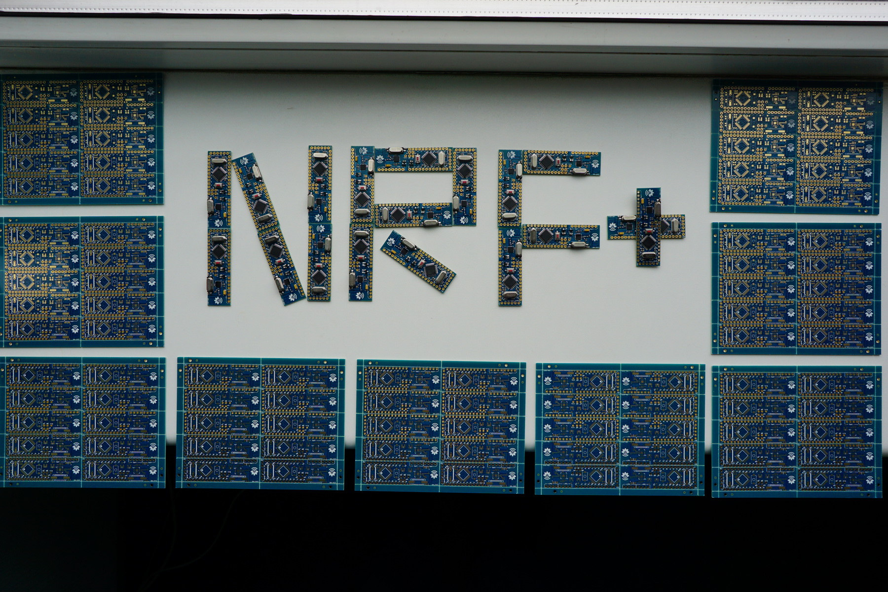
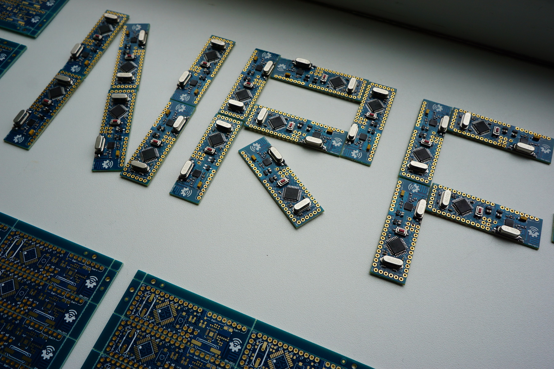
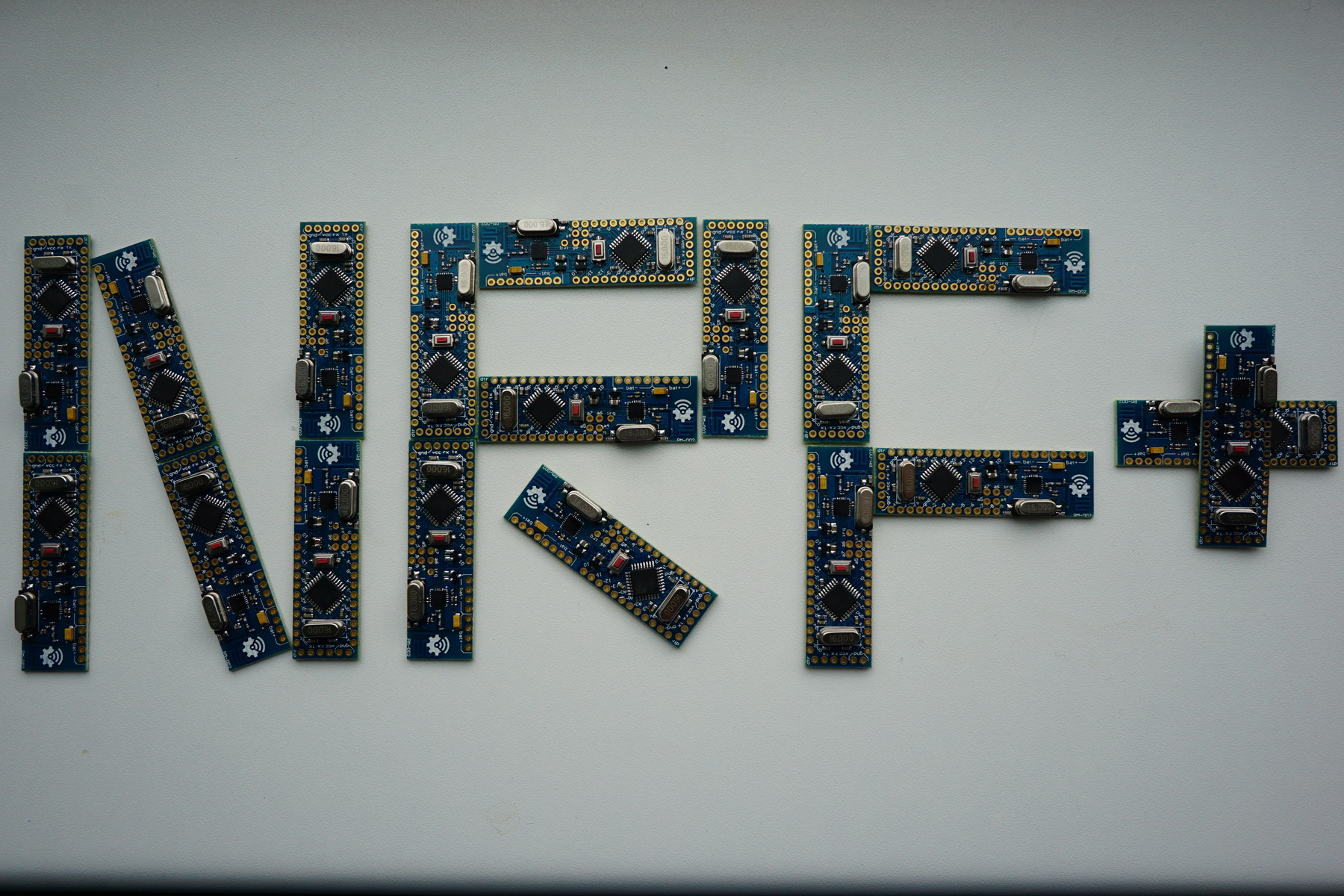
💬 MySensors Stable Node
-
Manually mounted, as in hand soldered? 1$ per board? I think that is a very optimistic price!
I've looked through old emails from various smd assembly houses.. I got one that states setup fee for around 140$ (per batch), and then 4-5$ per unit.. add to that stencil price 60$ (Can be used for multiple batches). and don't forget the BOM price as well..
I know that they are spitting out cheap arduino nano's for 1-2$.. but they are probably not quality checked, just smd assembly, bagged and shipped.. (and they probably make 5000 - 50.000 units per batch)
I think that people need to be realistic on what they can get, at what prices..
-
also, check this blogpost out..
-
@tbowmo
Thanks for information. But you are painting a bleak pictiure, I think.@tbowmo said:
add to that stencil price 60$ (Can be used for multiple batches)
No. Size(widthxlength) Useful area(width×length) Price Weight/pc
1 37.0cm×47.0cm 19.0cm×29.0cm usd17/pc 1.5KG
2 30.0cm×40.0cm 13.0cm×21.0cm usd15/pc 1KG
3 42.0cm×52.0cm 24.0cm×34.0cm usd30/pc 1.8KGThese are prices from my latest china pcb partner (hard stencil with frame)
@tbowmo said:
setup fee for around 140$ (per batch)
My latest local pcba partner offered 50$ price for SMT machine set up (automatic assebmbly, ultra low quantity batch)
@tbowmo said:
Manually mounted, as in hand soldered? 1$ per board? I think that is a very optimistic price!
I hope it's not far from reality. My latest local pcba partner has assembled board with 2.2cent for solder point (manual assembly, ultra low quantity batch)
It would be perfect to find a PCBA partner (maybe with pcb production and components stock, turn-key service) in China (with perfect logistics)
-
Of course prices do vary between manufacturers, The prices that I listed was a couple of years old, so they have probably changed a bit..
I just want to point out that pcb assembly can not be done for 'free' As there is a lot of factors that has to be calculated into the price..
-
Looks like what I have been looking for !
Any progress on the gerber files ? ( so I can order pcb's )
I was looking through the list of materials, but getting confusion while looking on Aliexpress, is it possible to share the links to the parts on Aliexpress/eBay ?
Thanks !
Alex
-
@Slorf Sorry for delay. I've uploaded gerber files (100% correct - first batch was produced according to them).
I ordered 0402 components in these shops:
http://www.aliexpress.com/store/1171142
http://www.aliexpress.com/store/821060
-
Sorry, i am confused
How do i recognize the 4.7uf polarised capacitor ?
Thanks !!
Alex
-
-
This would be the first pcb's i order, how do i know which component goes where on the pcb ?
-
How do i know it;s a polarized version ?
There are these ( which i think are the wrong ones )
http://www.aliexpress.com/item/Free-shipping-0805-SMD-capacitor-4-7uf-50V-475Z-100PCS/32376068362.html?spm=2114.01010208.3.40.rvV9hM&ws_ab_test=searchweb201556_9,searchweb201644_4_505_506_503_504_10020_502_10001_10002_10017_10010_10005_10011_10006_10003_10021_10004_10022_10009_10008_10018_10019,searchweb201560_2,searchweb1451318400_-1,searchweb1451318411_6452&btsid=833ff5df-930f-4fd8-8530-cb280a1b9c7fand there are these:
-
@Slorf OK. Use non-polarized (ceramic) capacitor 0805 4.7uF and polarized 10uf (yellow 3216) capacitor. I've changed bom.
I've uploaded assembly pdf too :).
-
Thanks, i found everything on Aliexpress, except:
Push Button SPDT
Resistor 1M ( which package size )Alex
-
@Slorf
Resistor 1M ( which package size ) - unnecessary element (R1 can be mounted for backward compatibility with nRF24L01, nevermind)
Push Button - use any buttons like these http://ru.aliexpress.com/item/10-Pcs-x-Sealed-SMD-Momentary-Tact-Tactile-Push-Button-Switch-3mm-x-6mm-x-2/32600602500.html?spm=2114.30010708.3.10.QkNxnX&ws_ab_test=searchweb201556_6,searchweb201644_3_505_506_503_504_301_10020_502_10001_10002_10017_10010_10005_10006_10011_10003_10021_10004_10022_10009_10007_10008_10018_10019,searchweb201560_3,searchweb1451318400_-1,searchweb1451318411_6451&btsid=efafd213-4a02-41ac-8d40-b5e9982a58f1
-
-
Hi,
When I try and order the pcb's from dirtypcb I get the following error:
PCB #17568: No board outline (.GML/.GKO/.GBR) file found.
I made a zip file with cam.drl, main.gbl, main.gbo, main.gbs, main.gtl, main.gto, main.gts
when I try to upload this on dirtypcb I get the error message that there is no board outline.regards
Alex
-
@Slorf It's openhardware.io engine problem. Engine had removed some files from my zip. Use files from this complete archive (gm2 - mechanical layer, rename it if its nessesary).
0_1456686721977_nrf_17_01_fabr.zip
-
.gm2 was a new extension I didn't know about.
I've updated the file extraction engine. When you get a chance, please try uploading it again.
-
@hek
Thanks for quick fix
gm2 = gerber mechanic layer2. So there are many variations of file extensions. I think it would be perfect to add ability to attach a file with custom extension or raw zip\rar without extraction.
-
I renamed the gm2 file to gml ( see: http://jrainimo.com/build/?p=642 ), and was able to order it from dirtypcb.
Alex
-
@Slorf One detail.... If it is not so late - please change your order (sorry...). Board thikness must be 1.6mm (antenna tunned for this value). I've changed board description.
-
I mailed the people at dirtypcb, hopefully they can change it for me.
If they cannot change it, would it be possible to get rid of the antenna and mount a pa/lna antenna ?
Regards
Alex
-
@Slorf Do not worry. Antenna will work with any board thikness, but with 1.6mm (with current geomerty configuration) it will be optimal. Almost all china nrf modules (I've seen) have non optimal antenna geometry.
PS
I'am sorry I hope dirtypcb will change you order.@Slorf said in MySensors Stable Node:
it be possible to get rid of the antenna and mount a pa/lna antenna ?
It is possible, but its very non technologically...
-
Great board.
Did you test the performance ? Like number of recieved packets per second ?
-
Let's hope the change it
Would it be possible to mount something like this on the pcb ?
-
Couple of questions
How to mount the second Quartz crystal ?, there are no holes in the pcb
The LDO regulators are mounted next to 4.7uf capacitors, is it correct that the regulators and capacitors are connected to eachother on both sides ?
On the photo of the assembled pcb it looks like this, but on the photo of the plain pcb and the schematic it look different.
| Pin 1 IC3 Pin2 | | Pin 3 Are pin 2 and 3 also connected to the capacitor left and right pin ? Left pin | C14 | Right pin
Thanks !!
Alex
-
@Slorf
Q1? Q1 is smd quartz. Q2 can be smd too but it can be difficult to mount it (so I've placed holes).I do not understand about LDO. You can check pinout in datasheet http://www.torexsemi.com/products/voltage_regulators/data/XC6206.pdf . May be datasheet schematic model (picture) is different from my library schematic model. But schematic and layout are correct.
-
Hi, the bom says 2 x quartz crystal
I did not know they where different and one should be smd.
Could you tell me which quartz crystals I should get ?
Will check out the datasheet for the LDO
Thanks
Alex
-
-
@Slorf I've left the package field in bom blank, so you can use any crystal you have. All components on the board are smd, so crystal should be smd too if you have it. But it may be difficult to place smd crystal as Q2 (too small area) and I've placed holes. I have both SMD and THD crystals but I will put holes in Q1 crystal pads in the next version too. Now you can simply mount THD crystal on the pads, it's not difficult.
@Slorf said:
Would it be possible to mount something like this on the pcb?
It's possible. But I want this board to be as compact as possible.
@ahmedadelhosni said:
Great board.
Did you test the performance ? Like number of recieved packets per second ?Thanks. I've tested stability (for some months without troubles in typical applications) and RF range. I think it doesn't make sense to test performance with low performance mcu, but you can propose the sketch and I test with it.
-
I have both versions ( SMD and THD ) crystals on order with aliexpress now
As for the LDO regulators, I will wait for the PCB's to arrive before making assumptions
Now I have to wait some weeks before everything arrives ........and then my first smd soldering experience !
Alex
-
-
Hi,
Very nice project. Do you have a plan to sell assembled piece of the boards?
Soldering such small SMD is out of my skills
-
@fisher Thanks. I'm looking for good PCBA service.
-
@Koresh I'm looking forward. What do you think, what will be the price of a assembled piece?
-
@fisher The production of the first small batch is underway (manual mounting). So I wil have 20 boards for test next week. I will provide price estimate in a week.
-
@Koresh post pictures please
-
Hi @Koresh,
Sorry if this is a dumb question but I'm new to this. What's the minimum voltage to power this board? Is it the 1.9V from the NRF?
I'm thinking of building a node with this using a LiPo battery with a protected TP4056 charging module.
If me idea isn't impossible I'd be highly interested to buy some assembled units of this PCB.
Thanks!
-
@flozsc
Hi. Minimum operating voltage depends on clock frequency. Boards contain standard 16MHz crystal oscillator to full pro mini compatibility. If you use default bootloader and 16Mhz clock frequency, the board will work with a voltage above 2.7v (on the verge of stability). But you can use internal oscillator (custom arduino boards settings, for example 8MHz or 1MHz for lowerst operating voltage) with some limitations (like slower serial). In this case operating voltage should be above 2--2.1v (do not forget a little dropout of LDO regulator).
-
@Koresh Thanks for your quick reply.
Sleeping sometimes helps. After thinking over it again, I think I'll prepend a step-up converter to 5V behind the battery as most sensors at least require 3.3V or even 5V...
Looking forward to your update on the 20 test boards!
-
So far betatests for two modules soldered manually two weeks ago are good. I was using two analog inputs and 5 digital outputs. Radio is rock stable also.
-
Impressive !!
did you reflow the board, or did you REALLY manually solder the nrf24l chip with an iron ???
-
@fifipil909 Thanks.
I've soldered these boards using simple soldering iron and hot air fan (lukey 702).
-
First small batch is completed
-
excellent
-
Nice !!!
I am still waiting for some parts to arrive from china
Alex
-
Wow ! I really like the color and design.
Waiting for alpha testing of the nrf chip.
Is soldering it more difficult than soldering the atmega as they are not the same package type ?
-
@Koresh what about price for assembled boards?
-
@robosensor So far 9-10$ for each board. Small batch and not mass production soldering... Negotiating smd services for PCBA. Hope to reduce costs by $2 final. Will see what happens.
-
@ahmedadelhosni said:
Is soldering it more difficult than soldering the atmega as they are not the same package type ?
3 steps process:
- tin-plating the board contacts
- tin-plating the chip contacts
- apply flux-gel and place chip on the board and heat it with soldering Heat Blower - pre-heat-wait-heat-wait . Like standard soldering profile http://www.renesas.eu/products/lead/specific_info/rt/heatproof/index.jsp .
also need to have a good ayes ))) the flux-gel should be the one you do not have to remove after.
-
You make some... I'll buy some... great work!
-
Alfa testing:
Checking radios as various nodes. Currently working as 2 relay nodes, DHT 22 temperature node and gateway.
All is good . Range 1-2 meters less than NRF24 with big antenna in apartment surrounding.
Digital pins cheeked like in the video: https://youtu.be/00fy9amZnt4
Analog pins tested with generic arduino light sensor. So radios and pins are OK.
-
@Sander-Teunissen said:
You make some... I'll buy some... great work!
So far still negotiating\finding reliable PCBA. First batch of 17 boards Koresh and me we were not impressed.
-
Keep me posted!
Will order when board comes soldered and ready to use!
-
Congratulations !!! Best hardware project indeed !
-
I would be all over this (would get a dozen!) if using RF69. Should be handy enough to modify? I better start watching those KiCad tutorials!
-
@GertSanders Thanks!
@shabba I've almosted completed new ultrasmall radionode based on rfm69. I'am very busy now but I hope to finish all tests in a week. I will post board asap
-
@Koresh wow looks promising I can't wait!!! I thought that sub Ghz antenna is bigger than 2.4ghz??
-
I would think we would solder on out own antenna.
-
oh maybe I didn't understand well, I thought that semtech ic (rfm69) would be onboard?? because if we wire our antenna, I don't see well why not use rfm69 module instead. In case of pcb antenna trace, ic onboard makes more sense imho. but maybe I'm wrong..I thought to give a try to this sometimes ago but had this reflexion,..and good design of pcb antenna trace for 433-915mhz is a lot bigger than 2.4ghz nrf. and smaller trace, lower range..+ need to be tuned for each design (in theory, I'm not expert)
that's cool because koresh is skilled at this lot of thing to learn! so I can't wait to see or try one board!
-
Hi,
I got all the parts, but I think the NRF24L01 is the normal version and not the + version, there is no + to be found on the chip.
Would the older NRF24L01 ( without plus ) work on the board ?, or do I have to use the R1 resistor ?
( Resistor 1M ( which package size ) - unnecessary element (R1 can be mounted for backward compatibility with nRF24L01, nevermind)Alex
-
@Slorf It depends on crystal. If oscillator starts and works correctly some days you can omit it.
-
Ermm... how do I know it works correctly ?, and if it doesn't work correctly which 1M resistor do I have to use ?
Thanks for your help !!!
Alex
-
@Slorf NRF oscillator can work or not (or could stop after some time). If problems appear use any 1m resistor (0402 or 0603 if you can solder it). Do not worry. It is the last stage (after nrf soldering and atmega programming).
Can you provide link to your nrf chip(where you buy it)? I want to check it.
-
Sorry for the late reply, our second son was born just 2 weeks ago.... no sleep anymore
It looks like this one, except mines it labelled: 0935VI, the one on the link 0935VJ
-
-
-
@koresh Just created a light sensor from one of the boards I bought from you. It works great !
I had to do some tweaking with the serial monitor speed from my arduino IDE (I had to double the speed which was set in the code or something)
I also had to press the reset button just before uploading of the sketch started.
Apart from that: Great !
Thanks !
-
@Sander-Teunissen
Thanks to your responce.
I'm sorry to hear you faced some hardware problem. Of course the board must restart itself. It may be couse of low quality of mounting first boards or it was damaged during delivery
May be you used incorrect usb-ttl converters boards without correct dtr line? I faced them year ago.. it was bad surprise )
-
@Koresh No problems. I am happy working with them.
-
@Koresh I guess I already know the answer, but this board works with 3.3 volts ? If I want to connect something like this:
https://www.mysensors.org/build/motion ,which works only on 5V I'd need to add a step up converter ?Sander.
-
@Sander-Teunissen said:
@Koresh I guess I already know the answer, but this board works with 3.3 volts ? If I want to connect something like this:
https://www.mysensors.org/build/motion ,which works only on 5V I'd need to add a step up converter ?Sander.
Board contains two 3.3v LDO. You can change one of them to 5v (do not forget check schematic).
-
@Sander-Teunissen you can modify the motion sensor to work on 3.3V (see http://www.instructables.com/id/Convert-a-5v-PIR-Motion-Sensor-to-33v-for-ESP8266/)
-
@Koresh can you give us an ETA of the sensor? I'm looking forward to buy some
-
Hi,
I aasembled your node, but the radio chip version is not the + one. After burning the MYS bootloader is prints the debug in serial:
60110 TSM:FAIL:RE-INIT
60112 TSM:INIT
60119 !TSM:INIT:TSP FAIL
60123 TSM:FAIL:CNT=7
60125 TSM:FAIL:PDTAny suggestions?
-
@Tigroenot said:
Hi,
I aasembled your node, but the radio chip version is not the + one. After burning the MYS bootloader is prints the debug in serial:
60110 TSM:FAIL:RE-INIT
60112 TSM:INIT
60119 !TSM:INIT:TSP FAIL
60123 TSM:FAIL:CNT=7
60125 TSM:FAIL:PDTAny suggestions?
For not the + version you should mount 1M resistor (R21). And check all soldering points of course.
-
I checked everything twice of course. I don't have 0402 1M resistor, the smallest I have is 0805
-
@Tigroenot said:
I checked everything twice of course. I don't have 0402 1M resistor, the smallest I have is 0805
You can easily solder THD resistor in parallel with Q2
-
@Koresh Did that. No luck.
0 MCO:BGN:INIT NODE,CP=RNNNA--,VER=2.1.0-beta
4 TSM:INIT
4 TSF:WUR:MS=0
12 !TSM:INIT:TSP FAIL
14 TSM:FAIL:CNT=1
16 TSM:FAIL:PDT
-
Allright, I have replaced the nrf chips to those with + and... that was it, everything is working very well now
Here they are, freshly handmade
-
@Tigroenot
I'm really happy to see your success with these boards. Congratulations!
-
Very nice design ! I wish it was available for sale !
I have a question, though. Would it make sense to mutualize the Crystal between the NRF and the Atmel ?
-
@qqlapraline Thanks for your attention to this project. A small batch of these boards is ready. Boards are under tests (individually) and almost ready for sale. Unfortunatelly I have "small" technical troubles with ebay but hope to solve them soon. Otherwise you will be able to buy them via paypal directly soon
-
@qqlapraline said in MySensors Stable Node:
I have a question, though. Would it make sense to mutualize the Crystal between the NRF and the Atmel ?
(I love to quote myself )
-
@qqlapraline said in MySensors Stable Node:
I have a question, though. Would it make sense to mutualize the Crystal between the NRF and the Atmel ?
(I love to quote myself )
I saw your question the first time, but it is a relatively hard question so I read documentation before writing the answer. I think this is a not good idea, very many inconsistencies. First, NRF24L01+ chip has a requirement:
Input crystal amplitude and current consumption
The input signal should not have amplitudes exceeding any rail voltage. Exceeding rail voltage excites the
ESD structure and consequently, the radio performance degrades below specification. You must use an
external DC block if you are testing the nRF24L01+ with a reference source that has no DC offset (which is
usual with a RF source).If you want to be able to share atmega's crystal you must use Full Swing Crystal Oscillator mode (by default arduino uses Low Power Crystal Oscillator mode). You can set this mode without any problems via fuses, but in this case you can't power atmega from 5V (according nrf24L01+ requirement).
However in this case you can't use 16Mhz crystal because 3.3v/16Mhz is overclocked mode for the atmega 328p (I do not say your device will not work, I say atmel do not garantee stability in this case)
As you can see on the latest photo, I didn't solder atmega328p crystals at all and the chip uses an internal oscillator and is powered from 5V
-
Unfortunately I can't open my ebay shop right now. While I'm trying to open it, you can buy this board here: https://www.ebid.net/eu/for-sale/arduino-ide-compatible-controller-with-the-nordic-nrf24l01-radio-transceiver-156695123.htm
-
@koresh is it still possible to purchase this board? The ebid link doesn't work anymore.
-
@koresh is it still available for purchase? I tried the link that you posted i couldn't find there
-
I'm wondering what the minimum input voltage is. The description only says max. 6.5V input voltage from the battery, but does not say what the minimum is. Both the nrf24l01+ as well as the atmega328P work with 3.3V, so if I use three AA batteries, that should be fine, right? I suppose using two AA batteries is not enough?