💬 MySensors Stable Node
-
@Koresh I guess I already know the answer, but this board works with 3.3 volts ? If I want to connect something like this:
https://www.mysensors.org/build/motion ,which works only on 5V I'd need to add a step up converter ?Sander.
-
@Koresh I guess I already know the answer, but this board works with 3.3 volts ? If I want to connect something like this:
https://www.mysensors.org/build/motion ,which works only on 5V I'd need to add a step up converter ?Sander.
@Sander-Teunissen said:
@Koresh I guess I already know the answer, but this board works with 3.3 volts ? If I want to connect something like this:
https://www.mysensors.org/build/motion ,which works only on 5V I'd need to add a step up converter ?Sander.
Board contains two 3.3v LDO. You can change one of them to 5v (do not forget check schematic).
-
@Sander-Teunissen you can modify the motion sensor to work on 3.3V (see http://www.instructables.com/id/Convert-a-5v-PIR-Motion-Sensor-to-33v-for-ESP8266/)
-
Hi,
I aasembled your node, but the radio chip version is not the + one. After burning the MYS bootloader is prints the debug in serial:
60110 TSM:FAIL:RE-INIT
60112 TSM:INIT
60119 !TSM:INIT:TSP FAIL
60123 TSM:FAIL:CNT=7
60125 TSM:FAIL:PDTAny suggestions?
-
Hi,
I aasembled your node, but the radio chip version is not the + one. After burning the MYS bootloader is prints the debug in serial:
60110 TSM:FAIL:RE-INIT
60112 TSM:INIT
60119 !TSM:INIT:TSP FAIL
60123 TSM:FAIL:CNT=7
60125 TSM:FAIL:PDTAny suggestions?
@Tigroenot said:
Hi,
I aasembled your node, but the radio chip version is not the + one. After burning the MYS bootloader is prints the debug in serial:
60110 TSM:FAIL:RE-INIT
60112 TSM:INIT
60119 !TSM:INIT:TSP FAIL
60123 TSM:FAIL:CNT=7
60125 TSM:FAIL:PDTAny suggestions?
For not the + version you should mount 1M resistor (R21). And check all soldering points of course.
-
I checked everything twice of course. I don't have 0402 1M resistor, the smallest I have is 0805 :)
@Tigroenot said:
I checked everything twice of course. I don't have 0402 1M resistor, the smallest I have is 0805 :)
You can easily solder THD resistor in parallel with Q2 ;)
-
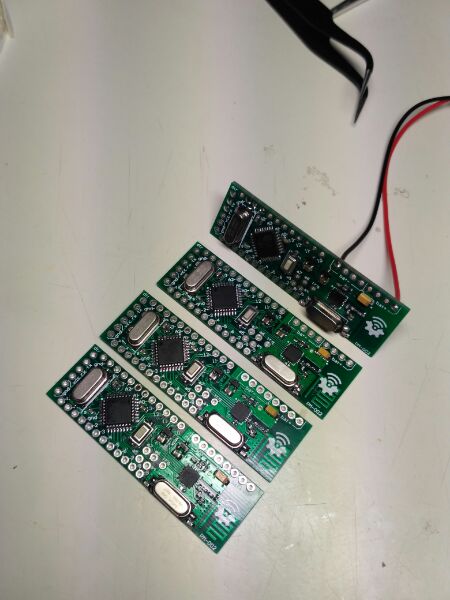
Allright, I have replaced the nrf chips to those with + and... that was it, everything is working very well now :)
Here they are, freshly handmade :)
@Tigroenot
I'm really happy to see your success with these boards. Congratulations! :thumbsup: -
Very nice design ! I wish it was available for sale !
I have a question, though. Would it make sense to mutualize the Crystal between the NRF and the Atmel ?
-
Very nice design ! I wish it was available for sale !
I have a question, though. Would it make sense to mutualize the Crystal between the NRF and the Atmel ?
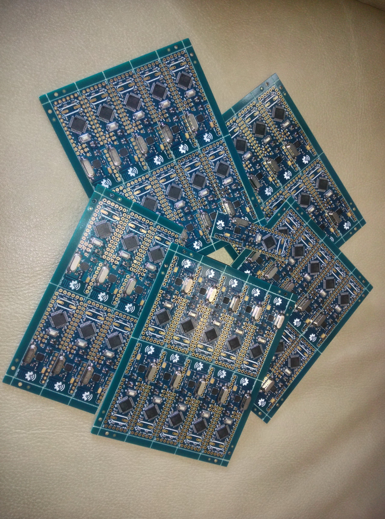
@qqlapraline Thanks for your attention to this project. A small batch of these boards is ready. Boards are under tests (individually) and almost ready for sale. Unfortunatelly I have "small" technical troubles with ebay :anguished: but hope to solve them soon. Otherwise you will be able to buy them via paypal directly soon :wink:
-
@qqlapraline said in 💬 MySensors Stable Node:
I have a question, though. Would it make sense to mutualize the Crystal between the NRF and the Atmel ?
(I love to quote myself :grin: )
-
@qqlapraline said in 💬 MySensors Stable Node:
I have a question, though. Would it make sense to mutualize the Crystal between the NRF and the Atmel ?
(I love to quote myself :grin: )
@qqlapraline said in 💬 MySensors Stable Node:
@qqlapraline said in 💬 MySensors Stable Node:
I have a question, though. Would it make sense to mutualize the Crystal between the NRF and the Atmel ?
(I love to quote myself :grin: )
I saw your question the first time, but it is a relatively hard question so I read documentation before writing the answer. I think this is a not good idea, very many inconsistencies. First, NRF24L01+ chip has a requirement:
Input crystal amplitude and current consumption
The input signal should not have amplitudes exceeding any rail voltage. Exceeding rail voltage excites the
ESD structure and consequently, the radio performance degrades below specification. You must use an
external DC block if you are testing the nRF24L01+ with a reference source that has no DC offset (which is
usual with a RF source).If you want to be able to share atmega's crystal you must use Full Swing Crystal Oscillator mode (by default arduino uses Low Power Crystal Oscillator mode). You can set this mode without any problems via fuses, but in this case you can't power atmega from 5V (according nrf24L01+ requirement).
However in this case you can't use 16Mhz crystal because 3.3v/16Mhz is overclocked mode for the atmega 328p (I do not say your device will not work, I say atmel do not garantee stability in this case)
As you can see on the latest photo, I didn't solder atmega328p crystals at all and the chip uses an internal oscillator and is powered from 5V :)
-
Unfortunately I can't open my ebay shop right now. While I'm trying to open it, you can buy this board here: https://www.ebid.net/eu/for-sale/arduino-ide-compatible-controller-with-the-nordic-nrf24l01-radio-transceiver-156695123.htm
-
Unfortunately I can't open my ebay shop right now. While I'm trying to open it, you can buy this board here: https://www.ebid.net/eu/for-sale/arduino-ide-compatible-controller-with-the-nordic-nrf24l01-radio-transceiver-156695123.htm
-
I'm wondering what the minimum input voltage is. The description only says max. 6.5V input voltage from the battery, but does not say what the minimum is. Both the nrf24l01+ as well as the atmega328P work with 3.3V, so if I use three AA batteries, that should be fine, right? I suppose using two AA batteries is not enough?