AC light dimmer with 2x TRIAC
-
Hello,
My name is Dovydas. This is my first post in this forum. When I start to interest in MySensors and started to connect wires, I was thinking that I want to control my AC bulb remotely. I start to looking info about it and I found description in Instructables about Arduino controlled AC light dimmer: http://www.instructables.com/id/Arduino-controlled-light-dimmer-The-circuit/?ALLSTEPS
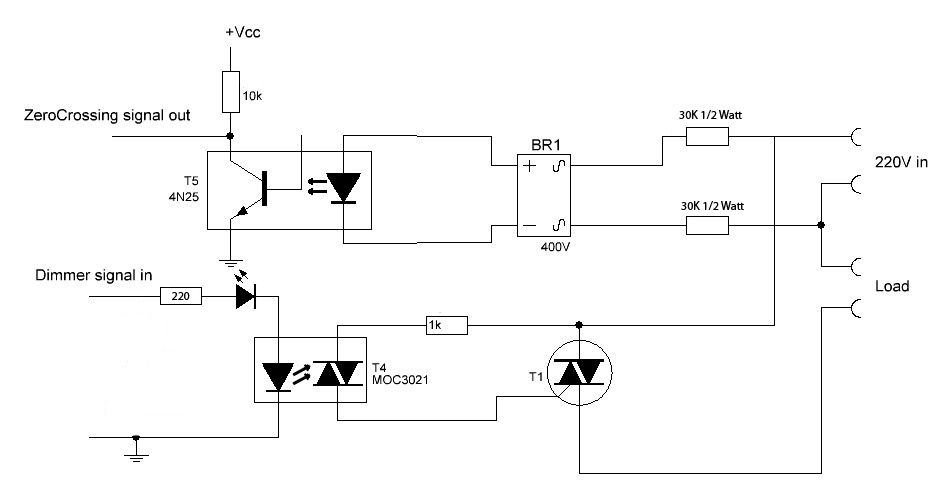
I connect the circuit on my breadboard (on the LOAD I connect AC light bulb):
Then I upload code to Arduino from STEP 4 in Instructables:
/*

AC Voltage dimmer with Zero cross detection
Author: Charith Fernanado <a href="http://www.inmojo.com">  http://www.inmojo.com

</a>
Adapted by DIY_bloke
License: Creative Commons Attribution Share-Alike 3.0 License.
Attach the Zero cross pin of the module to Arduino External Interrupt pin
Select the correct Interrupt # from the below table
(the Pin numbers are digital pins, NOT physical pins:
digital pin 2 [INT0]=physical pin 4 and digital pin 3 [INT1]= physical pin 5)
check: <a href="http://arduino.cc/en/Reference/attachInterrupt">  http://www.inmojo.com

</a>

Pin    |  Interrrupt # | Arduino Platform
---------------------------------------
2      |  0            |  All -But it is INT1 on the Leonardo
3      |  1            |  All -But it is INT0 on the Leonardo
18     |  5            |  Arduino Mega Only
19     |  4            |  Arduino Mega Only
20     |  3            |  Arduino Mega Only
21     |  2            |  Arduino Mega Only
0      |  0            |  Leonardo
1      |  3            |  Leonardo
7      |  4            |  Leonardo
The Arduino Due has no standard interrupt pins as an iterrupt can be attached to almosty any pin.

In the program pin 2 is chosen
*/
int AC_LOAD = 3;    // Output to Opto Triac pin
int dimming = 128;  // Dimming level (0-128)  0 = ON, 128 = OFF

void setup()
{
  pinMode(AC_LOAD, OUTPUT);// Set AC Load pin as output
  attachInterrupt(0, zero_crosss_int, RISING);  // Choose the zero cross interrupt # from the table above
}

//the interrupt function must take no parameters and return nothing
void zero_crosss_int()  //function to be fired at the zero crossing to dim the light
{
  // Firing angle calculation : 1 full 50Hz wave =1/50=20ms
  // Every zerocrossing thus: (50Hz)-> 10ms (1/2 Cycle)
  // For 60Hz => 8.33ms (10.000/120)
  // 10ms=10000us
  // (10000us - 10us) / 128 = 75 (Approx) For 60Hz =>65

  int dimtime = (75*dimming);    // For 60Hz =>65
  delayMicroseconds(dimtime);    // Wait till firing the TRIAC
  digitalWrite(AC_LOAD, HIGH);   // Fire the TRIAC
  delayMicroseconds(10);         // triac On propogation delay
				 // (for 60Hz use 8.33) Some Triacs need a longer period
  digitalWrite(AC_LOAD, LOW);    // No longer trigger the TRIAC (the next zero crossing will swith it off) TRIAC
}

void loop()  {
  for (int i=5; i <= 128; i++){
    dimming=i;
    delay(10);
   }
}
When I test it with real AC light bulb, everything working perfectly.
Then I was looking in already made MyS examples and found "DimmableLEDActuator" example, which is theoricaly should be suitable for same AC circuit, becose A|C circuit is controled by optocoupler MOC3021. So in one side MOC3021 is connected to DC circuit and in other side is connected to AC circuit. With DimmableLEDActuator I need to control only DC circuit.
The main step is, that I need to integrate 'interrupt function' zero_cross_int to MyS DimmableLEDActuator exampe. I was trying to do it, but becose I have no skills in programming I have no luck with it.
So, maybe someone could help me and explain how I could merge/integrate code from Instructables STEP 4 to DimmableLEDActuator code?Thank You!
-
Hello again,
I still trying to do it on my own :)
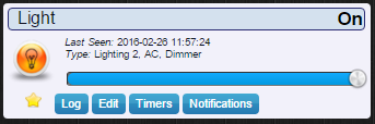
I combine 2 codes and I add sensor to Domoticz:
It is great, that I can control it: turn on or off. But if I set dim by percentage for example 14% - my AC light bulb is fully ON, like 100% and it's flickering. It seems like zero_crosss_int function not working.
My changed code:
/**
 * The MySensors Arduino library handles the wireless radio link and protocol
 * between your home built sensors/actuators and HA controller of choice.
 * The sensors forms a self healing radio network with optional repeaters. Each
 * repeater and gateway builds a routing tables in EEPROM which keeps track of the
 * network topology allowing messages to be routed to nodes.
 *
 * Created by Henrik Ekblad <henrik.ekblad@mysensors.org>
 * Copyright (C) 2013-2015 Sensnology AB
 * Full contributor list: https://github.com/mysensors/Arduino/graphs/contributors
 *
 * Documentation: http://www.mysensors.org
 * Support Forum: http://forum.mysensors.org
 *
 * This program is free software; you can redistribute it and/or
 * modify it under the terms of the GNU General Public License
 * version 2 as published by the Free Software Foundation.
 *
 *******************************
 *
 * REVISION HISTORY
 * Version 1.0 - February 15, 2014 - Bruce Lacey
 * Version 1.1 - August 13, 2014 - Converted to 1.4 (hek)
 *
 * DESCRIPTION
 * This sketch provides a Dimmable LED Light using PWM and based Henrik Ekblad
 * <henrik.ekblad@gmail.com> Vera Arduino Sensor project.
 * Developed by Bruce Lacey, inspired by Hek's MySensor's example sketches.
 *
 * The circuit uses a MOSFET for Pulse-Wave-Modulation to dim the attached LED or LED strip.
 * The MOSFET Gate pin is connected to Arduino pin 3 (LED_PIN), the MOSFET Drain pin is connected
 * to the LED negative terminal and the MOSFET Source pin is connected to ground.
 *
 * This sketch is extensible to support more than one MOSFET/PWM dimmer per circuit.
 * http://www.mysensors.org/build/dimmer
 */

#define SN "DimmableLED"
#define SV "1.1"

#include <MySensor.h>
#include <SPI.h>

#define LED_PIN 3      // Arduino pin attached to MOSFET Gate pin
#define FADE_DELAY 10  // Delay in ms for each percentage fade up/down (10ms = 1s full-range dim)
#define INTERRUPT 2  // The digital input you attached your sensor.  (Only 2 and 3 generates interrupt!)
int dimming = 128;  // Dimming level (0-128)  0 = ON, 128 = OFF

MySensor gw;

static int currentLevel = 0;  // Current dim level...
MyMessage dimmerMsg(0, V_DIMMER);
MyMessage lightMsg(0, V_LIGHT);


/***
 * Dimmable LED initialization method
 */
void setup()
{
  Serial.println( SN );
  gw.begin( incomingMessage );

  pinMode(LED_PIN, OUTPUT);// Set AC Load pin as output
  attachInterrupt(INTERRUPT, zero_crosss_int, RISING);  // Choose the zero cross interrupt # from the table above

  // Register the LED Dimmable Light with the gateway
  gw.present( 0, S_DIMMER );

  gw.sendSketchInfo(SN, SV);
  // Pull the gateway's current dim level - restore light level upon sendor node power-up
  gw.request( 0, V_DIMMER );

}


//the interrupt function must take no parameters and return nothing
void zero_crosss_int()  //function to be fired at the zero crossing to dim the light
{
  // Firing angle calculation : 1 full 50Hz wave =1/50=20ms
  // Every zerocrossing thus: (50Hz)-> 10ms (1/2 Cycle)
  // For 60Hz => 8.33ms (10.000/120)
  // 10ms=10000us
  // (10000us - 10us) / 128 = 75 (Approx) For 60Hz =>65


  int dimtime = (75*dimming);    // For 60Hz =>65
  delayMicroseconds(dimtime);    // Wait till firing the TRIAC
  digitalWrite(LED_PIN, HIGH);   // Fire the TRIAC
  delayMicroseconds(10);         // triac On propogation delay
         // (for 60Hz use 8.33) Some Triacs need a longer period
  digitalWrite(LED_PIN, LOW);    // No longer trigger the TRIAC (the next zero crossing will swith it off) TRIAC
}


/***
 *  Dimmable LED main processing loop
 */
void loop()
{
  gw.process();
}


void incomingMessage(const MyMessage &message) {
  if (message.type == V_LIGHT || message.type == V_DIMMER) {

    //  Retrieve the power or dim level from the incoming request message
    int requestedLevel = atoi( message.data );

    // Adjust incoming level if this is a V_LIGHT variable update [0 == off, 1 == on]
    requestedLevel *= ( message.type == V_LIGHT ? 100 : 1 );

    // Clip incoming level to valid range of 0 to 100
    requestedLevel = requestedLevel > 100 ? 100 : requestedLevel;
    requestedLevel = requestedLevel < 0   ? 0   : requestedLevel;

    Serial.print( "Changing level to " );
    Serial.print( requestedLevel );
    Serial.print( ", from " );
    Serial.println( currentLevel );

    fadeToLevel( requestedLevel );

    // Inform the gateway of the current DimmableLED's SwitchPower1 and LoadLevelStatus value...
    gw.send(lightMsg.set(currentLevel > 0 ? 1 : 0));

    // hek comment: Is this really nessesary?
    gw.send( dimmerMsg.set(currentLevel) );


    }
}

/***
 *  This method provides a graceful fade up/down effect
 */
void fadeToLevel( int toLevel ) {

  int delta = ( toLevel - currentLevel ) < 0 ? -1 : 1;

  while ( currentLevel != toLevel ) {
    currentLevel += delta;
    analogWrite( LED_PIN, (int)(currentLevel / 100. * 255) );
    delay( FADE_DELAY );
  }
}
I have add lines in DimmableLEDActuator Example:
- Before SETUP:
#define INTERRUPT 2 // The digital input you attached your sensor. (Only 2 and 3 generates interrupt!) int dimming = 128; // Dimming level (0-128) 0 = ON, 128 = OFF- In SETUP:
pinMode(LED_PIN, OUTPUT);// Set AC Load pin as output attachInterrupt(INTERRUPT, zero_crosss_int, RISING); // Choose the zero cross interrupt # from the table above- Function zero_crosss_int:
//the interrupt function must take no parameters and return nothing
void zero_crosss_int()  //function to be fired at the zero crossing to dim the light
{
  // Firing angle calculation : 1 full 50Hz wave =1/50=20ms
  // Every zerocrossing thus: (50Hz)-> 10ms (1/2 Cycle)
  // For 60Hz => 8.33ms (10.000/120)
  // 10ms=10000us
  // (10000us - 10us) / 128 = 75 (Approx) For 60Hz =>65


  int dimtime = (75*dimming);    // For 60Hz =>65
  delayMicroseconds(dimtime);    // Wait till firing the TRIAC
  digitalWrite(LED_PIN, HIGH);   // Fire the TRIAC
  delayMicroseconds(10);         // triac On propogation delay
         // (for 60Hz use 8.33) Some Triacs need a longer period
  digitalWrite(LED_PIN, LOW);    // No longer trigger the TRIAC (the next zero crossing will swith it off) TRIAC
}
Maybe there is some suggestions what I'm doing wrong?
-
Hello, again :)
It's working! Not very well, but at least its working.
Code bellow:
/**
 * The MySensors Arduino library handles the wireless radio link and protocol
 * between your home built sensors/actuators and HA controller of choice.
 * The sensors forms a self healing radio network with optional repeaters. Each
 * repeater and gateway builds a routing tables in EEPROM which keeps track of the
 * network topology allowing messages to be routed to nodes.
 *
 * Created by Henrik Ekblad <henrik.ekblad@mysensors.org>
 * Copyright (C) 2013-2015 Sensnology AB
 * Full contributor list: https://github.com/mysensors/Arduino/graphs/contributors
 *
 * Documentation: http://www.mysensors.org
 * Support Forum: http://forum.mysensors.org
 *
 * This program is free software; you can redistribute it and/or
 * modify it under the terms of the GNU General Public License
 * version 2 as published by the Free Software Foundation.
 *
 *******************************
 *
 * REVISION HISTORY
 * Version 1.0 - February 15, 2014 - Bruce Lacey
 * Version 1.1 - August 13, 2014 - Converted to 1.4 (hek)
 *
 * DESCRIPTION
 * This sketch provides a Dimmable LED Light using PWM and based Henrik Ekblad
 * <henrik.ekblad@gmail.com> Vera Arduino Sensor project.
 * Developed by Bruce Lacey, inspired by Hek's MySensor's example sketches.
 *
 * The circuit uses a MOSFET for Pulse-Wave-Modulation to dim the attached LED or LED strip.
 * The MOSFET Gate pin is connected to Arduino pin 3 (LED_PIN), the MOSFET Drain pin is connected
 * to the LED negative terminal and the MOSFET Source pin is connected to ground.
 *
 * This sketch is extensible to support more than one MOSFET/PWM dimmer per circuit.
 * http://www.mysensors.org/build/dimmer
 */

#define SN "DimmableLED"
#define SV "1.1"

#include <MySensor.h>
#include <SPI.h>

#define LED_PIN 3      // Arduino pin attached to MOSFET Gate pin
#define FADE_DELAY 10  // Delay in ms for each percentage fade up/down (10ms = 1s full-range dim)
//int dimming = 128;  // Dimming level (0-128)  0 = ON, 128 = OFF

MySensor gw;

static int currentLevel = 128;  // Current dim level...
MyMessage dimmerMsg(0, V_DIMMER);
MyMessage lightMsg(0, V_LIGHT);


/***
 * Dimmable LED initialization method
 */
void setup()
{
  Serial.println( SN );
  gw.begin( incomingMessage );

  pinMode(LED_PIN, OUTPUT);// Set AC Load pin as output
  attachInterrupt(0, zero_crosss_int, RISING);  // Choose the zero cross interrupt # from the table above

  // Register the LED Dimmable Light with the gateway
  gw.present( 0, S_DIMMER );

  gw.sendSketchInfo(SN, SV);
  // Pull the gateway's current dim level - restore light level upon sendor node power-up
  gw.request( 0, V_DIMMER );

}


//the interrupt function must take no parameters and return nothing
void zero_crosss_int()  //function to be fired at the zero crossing to dim the light
{
  // Firing angle calculation : 1 full 50Hz wave =1/50=20ms
  // Every zerocrossing thus: (50Hz)-> 10ms (1/2 Cycle)
  // For 60Hz => 8.33ms (10.000/120)
  // 10ms=10000us
  // (10000us - 10us) / 128 = 75 (Approx) For 60Hz =>65


  int dimtime = (75*currentLevel);    // For 60Hz =>65
  delayMicroseconds(dimtime);    // Wait till firing the TRIAC
  digitalWrite(LED_PIN, HIGH);   // Fire the TRIAC
  delayMicroseconds(10);         // triac On propogation delay
         // (for 60Hz use 8.33) Some Triacs need a longer period
  digitalWrite(LED_PIN, LOW);    // No longer trigger the TRIAC (the next zero crossing will swith it off) TRIAC
}


/***
 *  Dimmable LED main processing loop
 */
void loop()
{
  gw.process();
}


void incomingMessage(const MyMessage &message) {
  if (message.type == V_LIGHT || message.type == V_DIMMER) {

    //  Retrieve the power or dim level from the incoming request message
    int requestedLevel = atoi( message.data );

    // Adjust incoming level if this is a V_LIGHT variable update [0 == off, 1 == on]
    requestedLevel *= ( message.type == V_LIGHT ? 100 : 1 );

    // Clip incoming level to valid range of 0 to 100
    requestedLevel = requestedLevel > 100 ? 100 : requestedLevel;
    requestedLevel = requestedLevel < 0   ? 0   : requestedLevel;

    Serial.print( "Changing level to " );
    Serial.print( requestedLevel );
    Serial.print( ", from " );
    Serial.println( currentLevel );

    fadeToLevel( requestedLevel );

    // Inform the gateway of the current DimmableLED's SwitchPower1 and LoadLevelStatus value...
    gw.send(lightMsg.set(currentLevel > 0 ? 1 : 0));

    // hek comment: Is this really nessesary?
    gw.send( dimmerMsg.set(currentLevel) );


    }
}

/***
 *  This method provides a graceful fade up/down effect
 */
void fadeToLevel( int toLevel ) {

  int delta = ( toLevel - currentLevel ) < 0 ? -1 : 1;

  while ( currentLevel != toLevel ) {
    currentLevel += delta;
    analogWrite( LED_PIN, (int)(currentLevel / 100. * 255) );
    delay( FADE_DELAY );
  }
}
What I change:
- Comment line: int dimming = 128;
- Change 0 to 128 in line: static int currentLevel = 128; // Current dim level...
- After some reading, change interrupt line from defined comand to just 0 (it means arduino pin 2): attachInterrupt(0, zero_crosss_int, RISING); // Choose the zero cross interrupt # from the table above
- In zero_crosss_int function change dimming to currentLevel: int dimtime = (75***currentLevel); // For 60Hz =>65
Problems:
- When I set dim level from Domoticz - its beeing set upside down. For exampe: when I set 100% dim in Domoticz - light bulb is shining at the lowest power. When I set 7% - light bulb is shining at max power.
- There is no graceful dim up or dim down. When I change dim level, light bulb flicker few times until it reach dim level I set.
Again, maybe someone knows how to fix this? :D
Thanks!
Try changing this line (not tested):
int dimtime = (75*currentLevel); // For 60Hz =>65to
int dimtime = (75* ( 128-currentLevel) ); // For 60Hz =>65Also remove this line to avoid the flicker:
analogWrite( LED_PIN, (int)(currentLevel / 100. * 255) );... and finally add this line right before the "fadeToLevel( requestedLevel );" , in order to convert 0-100 range into 0-128 range:
requestedLevel = map( requestedLevel, 0 , 100 , 0 , 128 );Good luck!
-
Try changing this line (not tested):
int dimtime = (75*currentLevel); // For 60Hz =>65to
int dimtime = (75* ( 128-currentLevel) ); // For 60Hz =>65Also remove this line to avoid the flicker:
analogWrite( LED_PIN, (int)(currentLevel / 100. * 255) );... and finally add this line right before the "fadeToLevel( requestedLevel );" , in order to convert 0-100 range into 0-128 range:
requestedLevel = map( requestedLevel, 0 , 100 , 0 , 128 );Good luck!
Thank You!
Now there leaves only problem with flickering.
I made a video for beter understanding: https://goo.gl/photos/FPY5peSVfEsMAYvK6
-
Thank You!
Now there leaves only problem with flickering.
I made a video for beter understanding: https://goo.gl/photos/FPY5peSVfEsMAYvK6
-
Hey,
/** * The MySensors Arduino library handles the wireless radio link and protocol * between your home built sensors/actuators and HA controller of choice. * The sensors forms a self healing radio network with optional repeaters. Each * repeater and gateway builds a routing tables in EEPROM which keeps track of the * network topology allowing messages to be routed to nodes. * * Created by Henrik Ekblad <henrik.ekblad@mysensors.org> * Copyright (C) 2013-2015 Sensnology AB * Full contributor list: https://github.com/mysensors/Arduino/graphs/contributors * * Documentation: http://www.mysensors.org * Support Forum: http://forum.mysensors.org * * This program is free software; you can redistribute it and/or * modify it under the terms of the GNU General Public License * version 2 as published by the Free Software Foundation. * ******************************* * * REVISION HISTORY * Version 1.0 - February 15, 2014 - Bruce Lacey * Version 1.1 - August 13, 2014 - Converted to 1.4 (hek) * * DESCRIPTION * This sketch provides a Dimmable LED Light using PWM and based Henrik Ekblad * <henrik.ekblad@gmail.com> Vera Arduino Sensor project. * Developed by Bruce Lacey, inspired by Hek's MySensor's example sketches. * * The circuit uses a MOSFET for Pulse-Wave-Modulation to dim the attached LED or LED strip. * The MOSFET Gate pin is connected to Arduino pin 3 (LED_PIN), the MOSFET Drain pin is connected * to the LED negative terminal and the MOSFET Source pin is connected to ground. * * This sketch is extensible to support more than one MOSFET/PWM dimmer per circuit. * http://www.mysensors.org/build/dimmer */ #define SN "DimmableLED" #define SV "1.1" #include <MySensor.h> #include <SPI.h> #define LED_PIN 3 // Arduino pin attached to MOSFET Gate pin #define FADE_DELAY 10 // Delay in ms for each percentage fade up/down (10ms = 1s full-range dim) //int dimming = 128; // Dimming level (0-128) 0 = ON, 128 = OFF MySensor gw; static int currentLevel = 128; // Current dim level... MyMessage dimmerMsg(0, V_DIMMER); MyMessage lightMsg(0, V_LIGHT); /*** * Dimmable LED initialization method */ void setup() { Serial.println( SN ); gw.begin( incomingMessage ); pinMode(LED_PIN, OUTPUT);// Set AC Load pin as output attachInterrupt(0, zero_crosss_int, RISING); // Choose the zero cross interrupt # from the table above // Register the LED Dimmable Light with the gateway gw.present( 0, S_DIMMER ); gw.sendSketchInfo(SN, SV); // Pull the gateway's current dim level - restore light level upon sendor node power-up gw.request( 0, V_DIMMER ); } //the interrupt function must take no parameters and return nothing void zero_crosss_int() //function to be fired at the zero crossing to dim the light { // Firing angle calculation : 1 full 50Hz wave =1/50=20ms // Every zerocrossing thus: (50Hz)-> 10ms (1/2 Cycle) // For 60Hz => 8.33ms (10.000/120) // 10ms=10000us // (10000us - 10us) / 128 = 75 (Approx) For 60Hz =>65 int dimtime = (75* (128-currentLevel)); // For 60Hz =>65 delayMicroseconds(dimtime); // Wait till firing the TRIAC digitalWrite(LED_PIN, HIGH); // Fire the TRIAC delayMicroseconds(10); // triac On propogation delay // (for 60Hz use 8.33) Some Triacs need a longer period digitalWrite(LED_PIN, LOW); // No longer trigger the TRIAC (the next zero crossing will swith it off) TRIAC } /*** * Dimmable LED main processing loop */ void loop() { gw.process(); } void incomingMessage(const MyMessage &message) { if (message.type == V_LIGHT || message.type == V_DIMMER) { // Retrieve the power or dim level from the incoming request message int requestedLevel = atoi( message.data ); // Adjust incoming level if this is a V_LIGHT variable update [0 == off, 1 == on] requestedLevel *= ( message.type == V_LIGHT ? 100 : 1 ); // Clip incoming level to valid range of 0 to 100 requestedLevel = requestedLevel > 100 ? 100 : requestedLevel; requestedLevel = requestedLevel < 0 ? 0 : requestedLevel; Serial.print( "Changing level to " ); Serial.print( requestedLevel ); Serial.print( ", from " ); Serial.println( currentLevel ); requestedLevel = map( requestedLevel, 0 , 100 , 0 , 128 ); fadeToLevel( requestedLevel ); // Inform the gateway of the current DimmableLED's SwitchPower1 and LoadLevelStatus value... gw.send(lightMsg.set(currentLevel > 0 ? 1 : 0)); // hek comment: Is this really nessesary? gw.send( dimmerMsg.set(currentLevel) ); } } /*** * This method provides a graceful fade up/down effect */ void fadeToLevel( int toLevel ) { int delta = ( toLevel - currentLevel ) < 0 ? -1 : 1; while ( currentLevel != toLevel ) { currentLevel += delta; // analogWrite( LED_PIN, (int)(currentLevel / 100. * 255) ); delay( FADE_DELAY ); } } -
You must declare variables as 'volatile' to ensure they will be updated during interrupts. Try changing:
static int currentLevel = 128; // Current dim level...into
volatile int currentLevel = 128; // Current dim level...And to ensure no triac firing at zero level, try something like this at beginning of zero_cross_int() (before the "int dimtime"):
if ( currentLevel == 0 ) return;Good luck again!
-
Thanks!
Now when light bulb shining in 100% and I turn it off, it graceful goes to 0% with fading.
When I turn it on, bulb also graceful goes to 100%, but when max power had been reached - power instantly goes to 0% and in Domoticz status leaves as ON.
But if I use slipper to set 100% - dim level leaves and light bulb is shining as 100%.When I use slipper to set dim between 0% and 100% there still shows up flickering.
What about that line which one we used before:
analogWrite( LED_PIN, (int)(currentLevel / 100. * 255) );Maybe this line marks the end, when ligh bulb is going up from 0% to 100%?
Is this possible? -
Thanks!
Now when light bulb shining in 100% and I turn it off, it graceful goes to 0% with fading.
When I turn it on, bulb also graceful goes to 100%, but when max power had been reached - power instantly goes to 0% and in Domoticz status leaves as ON.
But if I use slipper to set 100% - dim level leaves and light bulb is shining as 100%.When I use slipper to set dim between 0% and 100% there still shows up flickering.
What about that line which one we used before:
analogWrite( LED_PIN, (int)(currentLevel / 100. * 255) );Maybe this line marks the end, when ligh bulb is going up from 0% to 100%?
Is this possible?The analogWrite will fire the triac based on PWM concept, and not synched to zero_cross detection, so in my opinion it would bring more problems than solutions.
You might be suffering from electrical problems at your zero-cross circuit. It might be not detecting all zero-crosses (or false triggering).
Maybe if you have a oscilloscope you could check the activity in "zero-cross signal out" pin, it should give you precisely 100 pulses in one second, if working good.
Another try is to change the '75' constant at dimtime calculation, try increase and/or decrease it a bit, and watch the results...
-
Thank You for Your help! Unfortunately I don't have oscilloscope so I can't check the signal either.
I will try to change dimtime constant values :)
Thanks!
-
I wanted to post this topic in the general discussion as I want to make a "safe" AC control circuit and wanted some ideas.
I have already designed this circuit 2 years ago but every while I gain some new experience. I was programming the dimmer using PIC and I was using Real Time Operating System (RTOS) + using (delay) to create an accurate timing for firing the TRIAC after the Zero crossing is detected. It worked very fine. Ofcourse using delay is bad and blocks your code.
Afterwards I changed my code to use time interrupts instead of RTOS, and flickering was happening sometimes.
I am telling you this because this may be something wrong in your coding. So this is the first issue you have to revise.Second. A few months ago I found a better design in this link . It is also a dimmer circuit but I read the comments and people said that there is no choke component in the circuit. I read later and new that this means that an inductor must be added ( don't know where exactly ) but I knew later that pulsing in such circuits is not safe without a choke components. This may also cause this flicker as I have on some sites.
Third. I had a friend of mine who used to run his Home Automation for 3 years. He used the same simple design as you and he never reported any bad issues :) This really made me confused, as the link which I have shared above contains more componets ( capactitors + snubber circuit ) for safety, while my friend didn't add them. I have also to add that snubber circuits are needed with inductive loads only, and maybe this is way he didn't face any problem.
ohhh what a long reply :)
-
Hey,
@ahmedadelhosni
Thanks for long post ;)Safety is in first place. This circuit should be safer with snubber circuit, inductor and varistor. I miss something? DIAC is same purpose like varistor?
I look at few already made products in China. Im not realy sure about whats that in pictures, is that inductor or antenna for rf module :)
First smart switch from China:
Second smart switch from China:
Even more cheaper: Cheap smart switch
But theese switches are with relays.
@rvendrame
I was trying to change around dimtime constant values - and with no any good luck.Today I move last modified code to Arduino Mini Pro and test it. When I test it - there was no flickering at all. Only there is same problem with:
When I turn it on, bulb also graceful goes to 100%, but when max power had been reached - power instantly goes to 0% and in Domoticz status leaves as ON.
But if I use slipper to set 100% - dim level leaves and light bulb is shining as 100%.I will check it and try to figure out why this is happening. :)))
@jacikaas said:
When I turn it on, bulb also graceful goes to 100%, but when max power had been reached - power instantly goes to 0% and in Domoticz status leaves as ON.
But if I use slipper to set 100% - dim level leaves and light bulb is shining as 100%.I saw you still using 'static int' instead 'volatile int' for currentLevel . Did you try 'volatile int' ?
Apart from that, I don't see any other reason for that. Perhaps something into controller side (domoticz)? I use Vera Lite with similar arduino circuit as yours, and I never had this behavior in my setup.
-
If I understand, sometimes when you think you should be seeing 100%, the light is actually off?
You are counting on the triac to latch and hold until the next Zero Crossing. However a triac needs a certain level of current in order to latch. If you try to trigger it too early in the AC cycle (while the AC voltage is still close to zero, just starting to rise), the load may not provide enough current to latch the triac. This is especially true with some kinds of loads. For example, LED Xmas lisghts don't conduct until the AC instantaneous voltage rises above the combined Vfwd of 25-50 series LEDs.
One way to test this hypothesis is to lengthen the pulse. Or you could adjust your timing multiplier.
-
@jemish which module do you mean exactly?
The schematic in the first post is not suitable for inductive loads. -
@jemish maybe have a look at following blog-post: http://www.homemade-circuits.com/2012/04/how-to-use-triacs-for-inductive-loads.html
With this information you should be able to "improve" above schematic to be also able to handle inductive loads.If you have no clue about all that... maybe have a look at this module:
https://www.kemo-electronic.de/en/Light-Sound/Effects/Modules/M028-Power-control-110-240-V-AC-2600-VA.php
It can control AC Motors,
in combination with this module:
https://www.kemo-electronic.de/en/Transformer-Dimmer/Converter/M150-DC-pulse-converter.php
You can connect it safely to the arduino. -
@jemish maybe have a look at following blog-post: http://www.homemade-circuits.com/2012/04/how-to-use-triacs-for-inductive-loads.html
With this information you should be able to "improve" above schematic to be also able to handle inductive loads.If you have no clue about all that... maybe have a look at this module:
https://www.kemo-electronic.de/en/Light-Sound/Effects/Modules/M028-Power-control-110-240-V-AC-2600-VA.php
It can control AC Motors,
in combination with this module:
https://www.kemo-electronic.de/en/Transformer-Dimmer/Converter/M150-DC-pulse-converter.php
You can connect it safely to the arduino.@Oitzu i cant find the price of them on the site. Are they listed ?
Hello! It looks like you're interested in this conversation, but you don't have an account yet.
Getting fed up of having to scroll through the same posts each visit? When you register for an account, you'll always come back to exactly where you were before, and choose to be notified of new replies (either via email, or push notification). You'll also be able to save bookmarks and upvote posts to show your appreciation to other community members.
With your input, this post could be even better 💗
Register Login