-
@LastSamurai
If you look on the forum you should find my eagle library with footprints for the smd version. Otherwise just export it from my very narrow node designs.@GertSanders I tried to find the library here but I actually coudln't. Could you perhaps give me a hint where to find it? Thanks!
-
@LastSamurai for KiCad it's already in the mysensors repo: https://github.com/mysensors-kicad/mysensors_radios.pretty/blob/master/NRF24L01-SMD.kicad_mod
-
@GertSanders I tried to find the library here but I actually coudln't. Could you perhaps give me a hint where to find it? Thanks!
I have added my EAGLE library below:
0_1459411902291_NRF24L01plus.lbr
You can rename it because the forum adds the extra "0_1459411902291_" during upload.
-
Thank you for the help!
-
@GertSanders you can change the status of your node as "tested". It works just fine - one important thing to remember is to solder the 3.3v solderpad. A couple of observations:
-
I can no longer fit a single AAA battery holders, but a double one only (AA or AAA)
-
the holes for J1 are two small and I had to drill them out.
I have not tested ATSHA204A as I do not have all components yet.
-
-
@GertSanders you can change the status of your node as "tested". It works just fine - one important thing to remember is to solder the 3.3v solderpad. A couple of observations:
-
I can no longer fit a single AAA battery holders, but a double one only (AA or AAA)
-
the holes for J1 are two small and I had to drill them out.
I have not tested ATSHA204A as I do not have all components yet.
So you received the boards before I did :-)
I'm still waiting on them. They are "in the mail" or at least in the hands of my local mail service (any day now...).
Which type of header/connector did you use to mount in the J1 location ? If the holes are too narrow for the breakable two row male headers, I will adapt this (that is why it is still UNTESTED for me).
Indeed, one or two single AAA holders are not possible on this board. I found that the double battery holders actually are cheaper, and it allows avoiding two extra holes where the radio now sits.
Update: I checked the drill size of the part used in v3 to place the header, indeed this is 0,8mm (31 mil) instead of 1,016mm (40 mil).
In my v4 version I already switched to a wider header, and this one does have 40 mil drill diameter. It's good I did not do a panel with the v3 version. -
-
So you received the boards before I did :-)
I'm still waiting on them. They are "in the mail" or at least in the hands of my local mail service (any day now...).
Which type of header/connector did you use to mount in the J1 location ? If the holes are too narrow for the breakable two row male headers, I will adapt this (that is why it is still UNTESTED for me).
Indeed, one or two single AAA holders are not possible on this board. I found that the double battery holders actually are cheaper, and it allows avoiding two extra holes where the radio now sits.
Update: I checked the drill size of the part used in v3 to place the header, indeed this is 0,8mm (31 mil) instead of 1,016mm (40 mil).
In my v4 version I already switched to a wider header, and this one does have 40 mil drill diameter. It's good I did not do a panel with the v3 version.So you received the boards before I did :-)
Yes, I have got the boards in 3-4 days. Very quick
Which type of header/connector did you use to mount in the J1 location ? If the holes are too narrow for the breakable two row male headers, I will adapt this (that is why it is still UNTESTED for me).
I have used a single row header like this
http://www.protostack.com/connectors/headers/40-pin-2.54mm-snappable-single-row-header -
So you received the boards before I did :-)
Yes, I have got the boards in 3-4 days. Very quick
Which type of header/connector did you use to mount in the J1 location ? If the holes are too narrow for the breakable two row male headers, I will adapt this (that is why it is still UNTESTED for me).
I have used a single row header like this
http://www.protostack.com/connectors/headers/40-pin-2.54mm-snappable-single-row-header@alexsh1
Ordered from OSHPark ? -
@alexsh1
Ordered from OSHPark ? -
Did anyone successfully used kicad footprint for these guys?
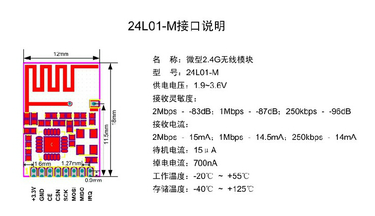
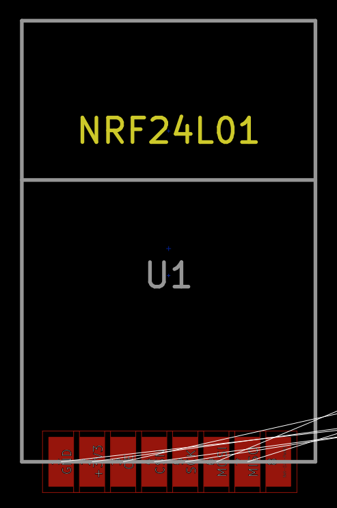
I received today my first PCB designed for the SMD version, did not work and overheated quite badly. After trying to troubleshoot it, frying a few things on the way, it seems to me that VCC / GND pad are switched between schematics and footprint:"Datasheet" from one of many aliexpress / ebay seller (all seems to be the same)
KiCad PCB view
I changed it on a local lib to reorder a new PCB and try, but if others can have a look at it, especially @tbowmo to update the official github repo if needed.
-
Did anyone successfully used kicad footprint for these guys?
I received today my first PCB designed for the SMD version, did not work and overheated quite badly. After trying to troubleshoot it, frying a few things on the way, it seems to me that VCC / GND pad are switched between schematics and footprint:"Datasheet" from one of many aliexpress / ebay seller (all seems to be the same)
KiCad PCB view
I changed it on a local lib to reorder a new PCB and try, but if others can have a look at it, especially @tbowmo to update the official github repo if needed.
-
@emc2 You have to be careful with these. As I discovered myself recently there are ones with PIN1 and PIN2 as VCC and GND and others with PIN1 and PIN8 as VCC and GND.
This is not well documented!@alexsh1 Damnit...
Never encountered a PIN1/PIN8 module yet. Are those with blob? I saw a few modules with black blob, often a big cristal and very cheap but I never ordered them.I have a few of this exact module, it has a datasheet on the website and wiring it as described work on a breadboard.
Did you encounter any PIN1 - GND, PIN2 - VCC so far?Problem may be somewhere else, probability that I screwed up my PCB design is high. I will see with the next PCB, with pin switched, if it's working.
-
@alexsh1 Damnit...
Never encountered a PIN1/PIN8 module yet. Are those with blob? I saw a few modules with black blob, often a big cristal and very cheap but I never ordered them.I have a few of this exact module, it has a datasheet on the website and wiring it as described work on a breadboard.
Did you encounter any PIN1 - GND, PIN2 - VCC so far?Problem may be somewhere else, probability that I screwed up my PCB design is high. I will see with the next PCB, with pin switched, if it's working.
-
Sorry about that, it was made in a jiffy one dark night, and I never got around to verify the footprint myself :(
I'll update the footprint later today (or you can make a PR on github and change it your self).
@tbowmo
Hey no worries, it's still a great ressource and so far I used it without any problem.I'm always confused by github when it came to PR etc but it should work. I just switched the coordinates of pad 1 and 2 it should do the trick.
Thanks!
Hello! It looks like you're interested in this conversation, but you don't have an account yet.
Getting fed up of having to scroll through the same posts each visit? When you register for an account, you'll always come back to exactly where you were before, and choose to be notified of new replies (either via email, or push notification). You'll also be able to save bookmarks and upvote posts to show your appreciation to other community members.
With your input, this post could be even better 💗
Register Login