PIR am312
-
-
Not sure if this is the same as the SR501 lens. Really hard to tell from the photo:
https://www.aliexpress.com/item-img/5Pcs-Lot-PIR-human-body-infrared-sensor-lens-Mini-lens-high-quality/32563535500.html?spm=2114.10010108.1000017.1.oavh25
If anyone finds a confirmed source for SR501 lenses, please post. -
SR501 lens is referenced as 8002-2. But it seems all those big fresnel lenses with 4 pins are the same, I suppose one original maker and a bunch of copycats.
-
sensitivity can be adapted in sw
For am312 ? How would you do that when all you have are Vcc, GND and signal pin ?
with timers. but, it's a bit more power hungry if using simple 8bits mcu, not a problem with more powerful mcus like ARM etc. which have more low power features.
-
sensitivity can be adapted in sw
For am312 ? How would you do that when all you have are Vcc, GND and signal pin ?
with timers. but, it's a bit more power hungry if using simple 8bits mcu, not a problem with more powerful mcus like ARM etc. which have more low power features.
with timers. but, it's a bit more power hungry if using simple 8bits mcu, not a problem with more powerful mcus like ARM etc. which have more low power features.
Still not getting it :)
This sounds more like a solution to manage "on" time when triggered but I don't get how this could make your sensor detect at 5m instead of 3m ? -
@Nca78
oki. lol i messed a bit with terms too :blush: yes for "on" time.
for 5m instead of 3m, this will depends of sensor quality and its lens. I think in datasheet they give a max range for an ideal lens, or that wouldn't make sense to get long range with a crappy lens.. -
@Nca78
oki. lol i messed a bit with terms too :blush: yes for "on" time.
for 5m instead of 3m, this will depends of sensor quality and its lens. I think in datasheet they give a max range for an ideal lens, or that wouldn't make sense to get long range with a crappy lens..@Nca78
oki. lol i messed a bit with terms too :blush: yes for "on" time.
for 5m instead of 3m, this will depends of sensor quality and its lens. I think in datasheet they give a max range for an ideal lens, or that wouldn't make sense to get long range with a crappy lens..So, Scalz, are you saying that out of the box, the am312 is hard-wired for max sensitivity, and then to get lower sensitivity, you add impairments, such as a lower duty cycle (less "ON" time) and/or a crappier lens? Wow, is that how this stuff is actually meant to work? I was hoping that maybe the am612 could be optionally tweaked for more sensitivity than the am312. If I'm understanding you (and if you're right), though, then I guess that won't be possible. I had assumed (perhaps wrongly) that the am312 defaulted to a "medium" amount of sensitivity, not a maximum amount of sensitivity. Do you happen to know whether am312 defaults to maximum sensitivity or not?
-
Anyhow, looking at the reference circuit design in the am612 "sensor manual" (see page 7 of http://akizukidenshi.com/download/ds/senba/Pir-Am612.pdf), I see that there is a photoresistor (a GL5528) there. Is it somehow adjusting the sensitivity based on the ambient light level? The GL5528 appears to be sensitive to 540nm light (i.e. green light) according to its datasheet
(http://akizukidenshi.com/download/ds/senba/GL55 Series Photoresistor.pdf). I'm not sure that's a trick that the am312 can do. Can it?I just love these Ford vs. Chevy debates. :)
By the way, where should that photoresistor be positioned? Under the IR lens, or should it have its own window? I'm guessing under the IR lens to keep things "tidy".
I just love these Ford vs. Chevy debates. :)
We are French, we only have Peugeot vs Citroën debates, or Renault vs Peugeot :D
Else @scalz misunderstood what we were talking about, he was just talking about changing the "on" duration of the sensor by software (as it's fixed on the am312). No the sensitivity.
About the photoresistor in the doc is connected to the OEN pin (Output ENable) of the AM612 (one more pin the am312 doesn't have), so that with the reference design it will only trigger and switch on the light when it's dark.
-
I recieved mine today and changed a HC-SR501 on a working Slim node to this but I failed to make it work.
I then tried to remove the voltage regulator (red arrow) and solder the jumper (blue) to power it from the bat but even with fresh batterys... no go! I watched the circuit to make sure i found VCC/GND and out but maybe i understood something wrong.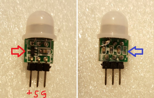
The second i put the old HC pir back that one worked again.
Any ideas?Controller: Proxmox VM - Home Assistant
MySensors GW: Arduino Uno - W5100 Ethernet, Gw Shield Nrf24l01+ 2,4Ghz
MySensors GW: Arduino Uno - Gw Shield RFM69, 433mhz
RFLink GW - Arduino Mega + RFLink Shield, 433mhz -
I recieved mine today and changed a HC-SR501 on a working Slim node to this but I failed to make it work.
I then tried to remove the voltage regulator (red arrow) and solder the jumper (blue) to power it from the bat but even with fresh batterys... no go! I watched the circuit to make sure i found VCC/GND and out but maybe i understood something wrong.The second i put the old HC pir back that one worked again.
Any ideas?Any chance you hooked up the polarity wrong when you tried it out? I did that to one of my three and completely fried it. It's dead.
Your PCB looks the same as mine, but the silkscreen is different. The polarity you marked on your photo looks correct to me, and it agrees with the "+" sign on your silkscreen. Mine didn't come with a "+" on the silkscreen.
Unrelated to your question, but I notice that yours came with a different lens. Do you have a link to where you bought yours?
-
Any chance you hooked up the polarity wrong when you tried it out? I did that to one of my three and completely fried it. It's dead.
Your PCB looks the same as mine, but the silkscreen is different. The polarity you marked on your photo looks correct to me, and it agrees with the "+" sign on your silkscreen. Mine didn't come with a "+" on the silkscreen.
Unrelated to your question, but I notice that yours came with a different lens. Do you have a link to where you bought yours?
@NeverDie http://www.ebay.com/itm/262527326905?_trksid=p2057872.m2749.l2649&ssPageName=STRK%3AMEBIDX%3AIT
I had two and tested them, maybe I fried them... but i dont think so.
Controller: Proxmox VM - Home Assistant
MySensors GW: Arduino Uno - W5100 Ethernet, Gw Shield Nrf24l01+ 2,4Ghz
MySensors GW: Arduino Uno - Gw Shield RFM69, 433mhz
RFLink GW - Arduino Mega + RFLink Shield, 433mhz -
@NeverDie http://www.ebay.com/itm/262527326905?_trksid=p2057872.m2749.l2649&ssPageName=STRK%3AMEBIDX%3AIT
I had two and tested them, maybe I fried them... but i dont think so.
Check to see how much current it's drawing when you have it powered up. If it's fried, it will be drawing more than expected.
Also, try connecting a voltmeter between the middle pin and ground with it powered on. When it detects motion, you'll notice a change in voltage.
-
@NeverDie http://www.ebay.com/itm/262527326905?_trksid=p2057872.m2749.l2649&ssPageName=STRK%3AMEBIDX%3AIT
I had two and tested them, maybe I fried them... but i dont think so.
The lens in your photo doesn't appear to match the lens in the ebay listed where you got it from. The lens in the ebay listing is the kind I have, which I'm not happy with. I hope you get yours working, as it would be nice to know if your lens works better than mine.
-
The lens in your photo doesn't appear to match the lens in the ebay listed where you got it from. The lens in the ebay listing is the kind I have, which I'm not happy with. I hope you get yours working, as it would be nice to know if your lens works better than mine.
@NeverDie thanks for your tips!
Will try it out and let you know about the lens. -
I just now threw together a primitive barebones breakout board for the AM612:
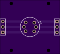
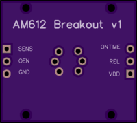
It wastes a lot of space because of the large SR501 lens cover that it's meant to go with. Also, it's really just "Plan B", as I'm hoping Version 1 of NCA78's PIR shield will work.
Nonetheless, if anyone wants the PCB files for my primitive breakout board, I can post them.
-
I just now threw together a primitive barebones breakout board for the AM612:
It wastes a lot of space because of the large SR501 lens cover that it's meant to go with. Also, it's really just "Plan B", as I'm hoping Version 1 of NCA78's PIR shield will work.
Nonetheless, if anyone wants the PCB files for my primitive breakout board, I can post them.
@NeverDie - well both modules draw 12uA and changes to 111uA on motion... reading on VCC. That would suggest they are working... strange I cant get an interupt then... I also see the battery voltage in motion and 0v when not on signal out... so thanks for the tips... the module is working. I just need to figure out why it doesnt trigger the interrupt.
I will work some more on this later... only thing that can trigger a interrupt is me touching the metal pinheader. Tried adding a capcitor but no luck.
Controller: Proxmox VM - Home Assistant
MySensors GW: Arduino Uno - W5100 Ethernet, Gw Shield Nrf24l01+ 2,4Ghz
MySensors GW: Arduino Uno - Gw Shield RFM69, 433mhz
RFLink GW - Arduino Mega + RFLink Shield, 433mhz -
@NeverDie - well both modules draw 12uA and changes to 111uA on motion... reading on VCC. That would suggest they are working... strange I cant get an interupt then... I also see the battery voltage in motion and 0v when not on signal out... so thanks for the tips... the module is working. I just need to figure out why it doesnt trigger the interrupt.
I will work some more on this later... only thing that can trigger a interrupt is me touching the metal pinheader. Tried adding a capcitor but no luck.
@sundberg84 said in PIR am312:
@NeverDie - well both modules draw 12uA and changes to 111uA on motion... reading on VCC. That would suggest they are working... strange I cant get an interupt then... I also see the battery voltage in motion and 0v when not on signal out... so thanks for the tips... the module is working. I just need to figure out why it doesnt trigger the interrupt.
I will work some more on this later... only thing that can trigger a interrupt is me touching the metal pinheader. Tried adding a capcitor but no luck.
Maybe your circuit needs a pull-up or pull-down resistor on the interrupt pin to make it work? That's what it sounds like.
-
@sundberg84 said in PIR am312:
@NeverDie - well both modules draw 12uA and changes to 111uA on motion... reading on VCC. That would suggest they are working... strange I cant get an interupt then... I also see the battery voltage in motion and 0v when not on signal out... so thanks for the tips... the module is working. I just need to figure out why it doesnt trigger the interrupt.
I will work some more on this later... only thing that can trigger a interrupt is me touching the metal pinheader. Tried adding a capcitor but no luck.
Maybe your circuit needs a pull-up or pull-down resistor on the interrupt pin to make it work? That's what it sounds like.
@NeverDie - A good idea again... just took for granted that was handeled in the sensor since im used to that with the other pirs... silly me. I will give it a shot later.
-
I got my am312 and I confirm the blind spots and a range of about 3 meters. I'll have to try to use a bigger lens from the 501 and see what happens.
PS I also compared side by side with a radar sensor and have to say I am impressed with the sensibility and the "all-around" visibility