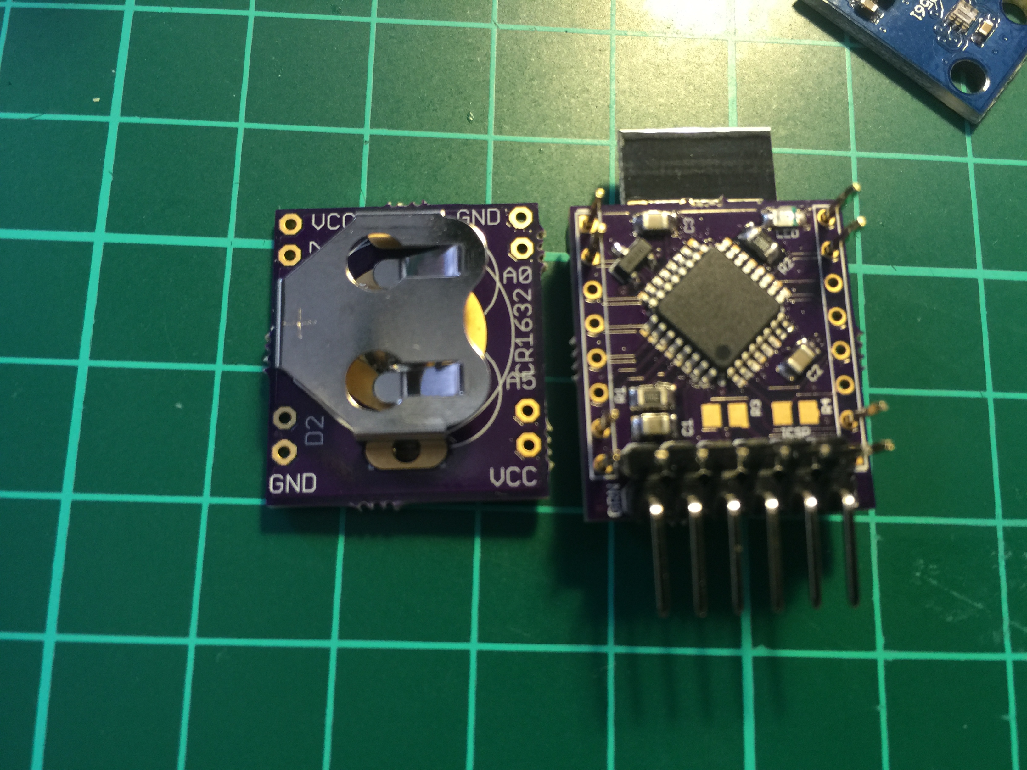
💬 Stamp size MySensor node
-
@GertSanders You are welcome :) Btw, if you just patch in support to generate random data for a nonce, you can use the soft signing backend on rPi.
Do you feel secure today? No? Start requiring some signatures and feel better tomorrow ;)
-
@GertSanders You are welcome :) Btw, if you just patch in support to generate random data for a nonce, you can use the soft signing backend on rPi.
@Anticimex
Well that sounds simple, but I'm more a hardware contributer, this is beyond my capabilities :-), especially in unix arena. I manage software developers for a living, so I know how much I do not know. -
Hello guys,
I am about to solder first PCB of this version. Just to be 100% sure, regarding C4 - what is the best value to use 1uF or 10uF, because I can see we can choose.
Regards,
MaciekRPI2 + RFLink + PiFace D2 + Aeon Z-Wave Gen5 + Foscams FI9821P&R2 + MySensors + UPS APC Back-UPS 950VA
RPI2 + RFXtrx433e + Foscams FI9821P + MySensors + UPS APC Back-UPS 950VA
RPIB+ + TP-Link MR3420 + Huawei E173 GarageDomoticz :) -
Hello guys,
I am about to solder first PCB of this version. Just to be 100% sure, regarding C4 - what is the best value to use 1uF or 10uF, because I can see we can choose.
Regards,
MaciekBetter to use 10uF. The schematic needs to be updated (still shows 1uF, I use 10uF now).
-
Thank you for the update,
Last part what I am missing is battery holder. I was trying to search it in many stores located in my country however I was not able to get it. Is there any internet shop when I can buy online? I have one workaround to soldier different CR battery holder and connect via wires.RPI2 + RFLink + PiFace D2 + Aeon Z-Wave Gen5 + Foscams FI9821P&R2 + MySensors + UPS APC Back-UPS 950VA
RPI2 + RFXtrx433e + Foscams FI9821P + MySensors + UPS APC Back-UPS 950VA
RPIB+ + TP-Link MR3420 + Huawei E173 GarageDomoticz :) -
Thank you for the update,
Last part what I am missing is battery holder. I was trying to search it in many stores located in my country however I was not able to get it. Is there any internet shop when I can buy online? I have one workaround to soldier different CR battery holder and connect via wires. -
@macieiks I bought the battery holder on http://www.ebay.co.uk/
-
@AWI I just put a link to an eBay. You put "Keystone 3013" in the search and hit search :-)
-
@alexsh1 do you plan to use this so small coincell with rfm69? very curious to see results regarding internal res during RX-Tx times...1.8V brownout should not be far i think..or maybe not :) because the voltage won't stay at 3v ;) but to counter effect, a nice capa at input with a current limiting resistor could help. reading/waiting voltage stabilize before transmitting can help too (I'm doing this with some CR2032 based nodes)
-
-
@alexsh1 do you plan to use this so small coincell with rfm69? very curious to see results regarding internal res during RX-Tx times...1.8V brownout should not be far i think..or maybe not :) because the voltage won't stay at 3v ;) but to counter effect, a nice capa at input with a current limiting resistor could help. reading/waiting voltage stabilize before transmitting can help too (I'm doing this with some CR2032 based nodes)
@scalz Yes, that's the plan, but I think I'll come across many difficulties. For now I have the nrf24l01+ version fully working. And started scratching the surface with RFM69. This is nrf24l01+ SMD version and swapping it for RFM69 is not going to be easy. So far I have not seen any adapters for the SMD version.
-
I have just updated a stamp size node to MySensors 2.1.1 and had to include the following into the sketch:
#define MY_RF24_CE_PIN 9
#define MY_RF24_CS_PIN 10
#define MY_SOFTSPI
#define MY_SOFT_SPI_SCK_PIN 13
#define MY_SOFT_SPI_MISO_PIN 12
#define MY_SOFT_SPI_MOSI_PIN 11The fist two lines are not required (it is in the MyConfig.h), but for me to understand how nrf24l01+ is connected.
I hope it helpsRegards
Alex -
Hi @GertSanders, @alexsh1
I'm considering to build a few nodes with this design, could anyone that have done and tested these give some feedback on how it work? Battery life etc. In my case I will mostly use it as window/door sensor and water leakage sensor so it would not send data to frequently.
Thanks for any input.
-
@GertSanders,
Thank you for the nice, small design. I'm trying to build one myself, but I'm running into issues burning the bootloader using the ArduinoISP sketch on an Arduino Nano (328). Looking at the schematics, the pins of the ICSP header (from left to right, if the headers are facing you) are:
Reset => Pin 10 of Nano
SCK => Pin 13 of Nano
MISO => Pin 12 of Nano
MOSI => Pin 11
VCC => VCC on Nano
GND => Gnd on NanoI set the board to Arduino Pro or Pro Mini in the Arduino IDE, selected Arduino as ISP and tried to burn the bootloader, but there always is the error message:
avrdude: Expected signature for ATmega328P is 1E 95 0F
Double check chip, or use -F to override this check.
Error while burning bootloader.Any idea what's wrong?
I built two copies of the board, and I get the same message with both. (mirroring the connectors of the ICSP header doesn't work, either).
Thanks a lot!
@reinhold
Hi, the first thing I would check is to see if you can burn a boot loader on a standard 328P DIP format with the Nano. I'm not sure the ISP sketch, when running on a Nano matches the exact physical pins for MISO, MOSI and SCK. So check that.
I also burnt the boot loader with the sketch, but on a classic Arduino UNO as ISP. Never tried to do this from a Nano as ISP. -
@reinhold
Hi, the first thing I would check is to see if you can burn a boot loader on a standard 328P DIP format with the Nano. I'm not sure the ISP sketch, when running on a Nano matches the exact physical pins for MISO, MOSI and SCK. So check that.
I also burnt the boot loader with the sketch, but on a classic Arduino UNO as ISP. Never tried to do this from a Nano as ISP.@reinhold
Something else I was thinking about. I did burn the boo loader before I mounted a NRF24L01+ board on my stamp size board.
I made another board recently and found that burning a boot loader while the radio is connected, gives me issues like the one you mention: sometimes an unexpected signature error, sometimes it starts and stop loading midway ... That was on a different board, but with basically the same connections between processor and radio.
So I think that you do need to load the boot loader before mounting the radio on the board. As for my newer board where I first found this issue, it was a robot control board I now need to redesign so that I can refresh the boot loader (ro anything else via ISP) with a mounted radio, by providing a "switch" of some kind to isolate the radio when I do not want it to interfere with the ISP loading. -
Hi @GertSanders, @alexsh1
I'm considering to build a few nodes with this design, could anyone that have done and tested these give some feedback on how it work? Battery life etc. In my case I will mostly use it as window/door sensor and water leakage sensor so it would not send data to frequently.
Thanks for any input.
@henninne sorry for a late reply. The battery life is excellent. I have one node working as a door sensor and another one I'm testing as a battery voltage sensor - just sends voltage every 60 mins. The door sensor is powered by two AAA batteries and has been working for 5-6 months and still shows 3.1V+
The battery sensor is running on a coin cell and consumes around 6uA while sleeping.