Controlling an inductive AC load
-
Martin, Thanks for the response. I just wired up a serial gateway last night and now I need to build me a sensor to test it with. I may try some kind of multi-sensor node to test this
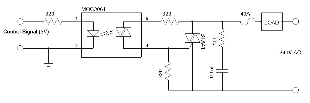
@dbemowsk I agree with @m26872 to have it save . There are many different types of ceiling fan types. Most available where I live are multiple (3) speed types which can easily be controlled with 3 "on/off" triac circuis (do include a snubber for the inductive load).
I suppose you are familiar with building triac circuits, make sure you have galvanic isolation (optocoupler). -
@m26872 I have never taken a dimmer apart myself. Is the circuit complex? I would prefer a schematic, but if the circuit is as simple as the one above I may be able to figure it out.
Vera Plus running UI7 with MySensors, Sonoffs and 1-Wire devices
Visit my website for more Bits, Bytes and Ramblings from me: http://dan.bemowski.info/ -
@m26872 I have never taken a dimmer apart myself. Is the circuit complex? I would prefer a schematic, but if the circuit is as simple as the one above I may be able to figure it out.
@dbemowsk You need to get the SSR relay connected to your arduino. I have it hooked up to my raspberry to remotely control 240V devices. You need to apply 3V to it in order to relay to switch on. Crydom is the top name though expensive. The same relay I have to control my hot water tank, which is heated at night (due to lower electricity cost).
This is a link to a similar relay. I have 50A one as I need to control 3kW heater:
http://uk.farnell.com/crydom/d2425/ssr-25a-24-280vac-3-32vdc-zero/dp/1200241 -
@alexsh1 An SSR will only turn the fan on and off. It will not allow any speed control which is what I am looking for. I currently have them connected to X10 inductive load dimmers and they work, but I am trying to see if I can move away from my X10 setup.
Vera Plus running UI7 with MySensors, Sonoffs and 1-Wire devices
Visit my website for more Bits, Bytes and Ramblings from me: http://dan.bemowski.info/ -
@alexsh1 An SSR will only turn the fan on and off. It will not allow any speed control which is what I am looking for. I currently have them connected to X10 inductive load dimmers and they work, but I am trying to see if I can move away from my X10 setup.
-
These are the dimmers I use: https://www.x10.com/xpdi3-dimmer-120-vac-500w-inductive.html . I never pulled the dimmer apart and scoped it or anything like that, so I am not sure. Could use PWM for all I know.
Vera Plus running UI7 with MySensors, Sonoffs and 1-Wire devices
Visit my website for more Bits, Bytes and Ramblings from me: http://dan.bemowski.info/ -
These are the dimmers I use: https://www.x10.com/xpdi3-dimmer-120-vac-500w-inductive.html . I never pulled the dimmer apart and scoped it or anything like that, so I am not sure. Could use PWM for all I know.
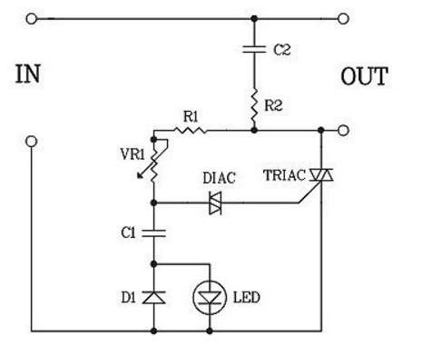
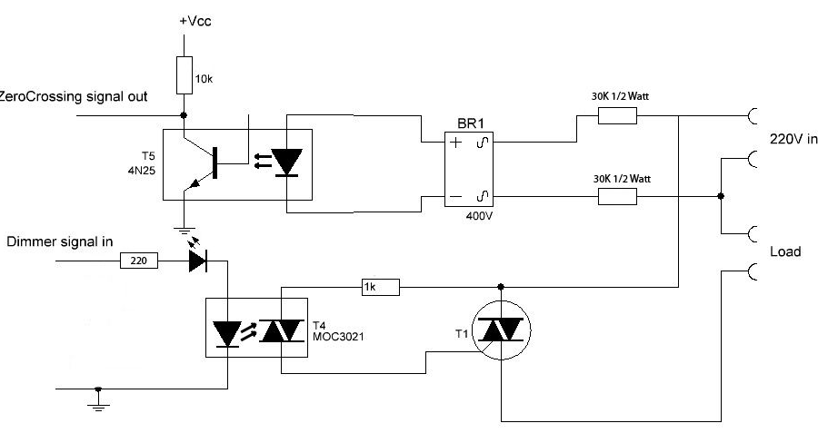
@dbemowsk this article describes how to build triac dimmers for inductive loads. The x10 dimmer you use is most probably like the type 2. And thus a phase cutting dimmer.
The circuit above is for on/off (SSD) and would need to be switched synchronized with the net frequency. There are a few examples on the forum on how to let the Arduino take care of that.
All assuming that your fan can take phase cutting dimming. -
So, do you think it would be possible to use something like this:
http://www.ebay.com/itm/DIMMER-AC-MOTOR-for-Fan-Light-Bulb-electric-1000-WATT-electronic-circuit-board-k-/282042936124?hash=item41ab11ab3c:g:2VMAAOSwxehXPWC3
and control it with something like an AD5171 Digital Pot in place of the pot that comes with the kit? -
So, do you think it would be possible to use something like this:
http://www.ebay.com/itm/DIMMER-AC-MOTOR-for-Fan-Light-Bulb-electric-1000-WATT-electronic-circuit-board-k-/282042936124?hash=item41ab11ab3c:g:2VMAAOSwxehXPWC3
and control it with something like an AD5171 Digital Pot in place of the pot that comes with the kit?@dbemowsk No... looking at the diagram there is no galvanic isolation.. .
This one requires to be isolated with plastic (including knob).The AD5171 is a nice piece of circuit but is not isolated either, would need a seperate power supply from your arduino and is not suited for high voltage/current AC environment. (and would make an expensive solution)
If you want to meet you expected lifetime (I don't want to contribute to someone death) you better take a safer approach..
A few options:
-
Another option mentioned by @m26872 was modifying an existing switch. I was thinking a switch like this:
http://www.menards.com/main/electrical/light-switches-dimmers-outlets/dimmer-fan-control-combination/legrand-2-5-amp-300-watt-de-hummer-fan-single-pole-control-dimmer/p-1444451193535-c-6322.htm?tid=1329371385801776297
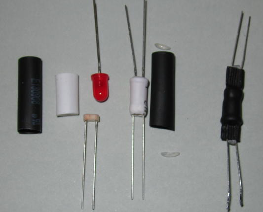
I could use the LED, LDR and shrink tube solution to get isolation as I would imagine that the switch just has 2 VR sliders. With that I would already have a combination switch that is designed to do what I want, I would just have to MySensorize it as @m26872 says. -
These are the dimmers I use: https://www.x10.com/xpdi3-dimmer-120-vac-500w-inductive.html . I never pulled the dimmer apart and scoped it or anything like that, so I am not sure. Could use PWM for all I know.
-
Another option mentioned by @m26872 was modifying an existing switch. I was thinking a switch like this:
http://www.menards.com/main/electrical/light-switches-dimmers-outlets/dimmer-fan-control-combination/legrand-2-5-amp-300-watt-de-hummer-fan-single-pole-control-dimmer/p-1444451193535-c-6322.htm?tid=1329371385801776297
I could use the LED, LDR and shrink tube solution to get isolation as I would imagine that the switch just has 2 VR sliders. With that I would already have a combination switch that is designed to do what I want, I would just have to MySensorize it as @m26872 says.@dbemowsk what you will find is a circuit very comparable to the ones mentioned.
To "MySensor"ize you you still need to control it from an arduino with (safe) stable power supply and isolation.Maybe easier to dismantle your x10 device.
It's hard to determine your experience level from your questions but you need to be able to:
- Build a (semi) digital motor control.
- Have little experience with an arduino MySensors device.
3.tie these together
-
@awi I have one of the X10 switches that I dismantled the other day and the issue with trying to use that is that there is so much circuitry for the X10 portion of the thing that without having a schematic, I wouldn't know exactly what to disconnect to only leave the triac motor control circuit. Also where and how to connect in my galvanic isolation circuit.
Hello! It looks like you're interested in this conversation, but you don't have an account yet.
Getting fed up of having to scroll through the same posts each visit? When you register for an account, you'll always come back to exactly where you were before, and choose to be notified of new replies (either via email, or push notification). You'll also be able to save bookmarks and upvote posts to show your appreciation to other community members.
With your input, this post could be even better 💗
Register Login