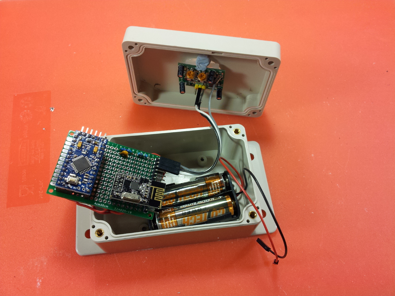
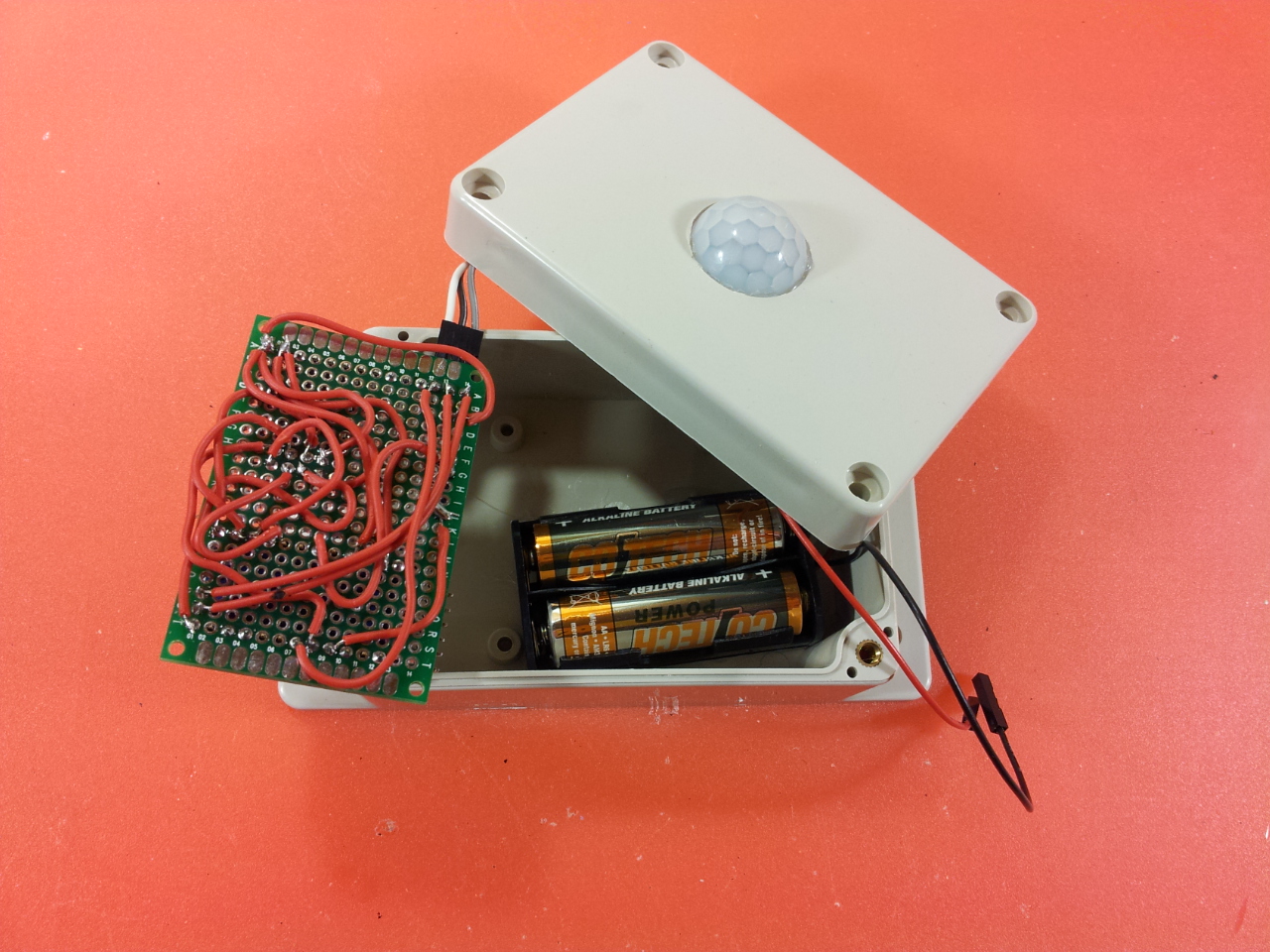
Battery Powered Motion Sensor
-
Did you follow this guide?
http://forum.mysensors.org/topic/225/hc-sr501-motion-sensor/11 -
I am using the following sleep time
unsigned long SLEEP_TIME = 1800000; // Sleep time between wakeup and voltage reporting (in milliseconds)
// Sleep until interrupt comes in on motion sensor. Send update every thirty minutes
gw.sleep(INTERRUPT,CHANGE,SLEEP_TIME);@lininger And you're not getting a ton of false positives from the sensor either I take it? Can you check if the sensor is actually sleeping reliably between interrupts/timers (even if it isn't detecting motion / HIGH)?
Looking at the forum I found two posts which may suggest that getting the motion sensor to work isn't entirely straightforward:
New interrupt: http://forum.mysensors.org/topic/225/hc-sr501-motion-sensor/18
Debouncer: http://forum.mysensors.org/topic/115/implementing-multiple-sensors/47
I'm not experienced enough with interrupts, debouncers and this particular sensor to make any suggestions but it seems likely that the solution is related. -
@lininger And you're not getting a ton of false positives from the sensor either I take it? Can you check if the sensor is actually sleeping reliably between interrupts/timers (even if it isn't detecting motion / HIGH)?
Looking at the forum I found two posts which may suggest that getting the motion sensor to work isn't entirely straightforward:
New interrupt: http://forum.mysensors.org/topic/225/hc-sr501-motion-sensor/18
Debouncer: http://forum.mysensors.org/topic/115/implementing-multiple-sensors/47
I'm not experienced enough with interrupts, debouncers and this particular sensor to make any suggestions but it seems likely that the solution is related.@bjornhallberg said:
And you're not getting a ton of false positives from the sensor either I take it? Can you check if the sensor is actually sleeping reliably between interrupts/timers (even if it isn't detecting motion / HIGH)?
3.3v modification of the HC-SR501. No floating, just make sure you run the HC-GND to the Arduino-GND close to the RAW Pin (I read about this somewhere on this board I believe). If I placed the HC-GND at any other point (including the Arduino-GND next to pin 2) the HC-OUT would float all over the place. Also allow a few seconds for the sensor to settle after applying power.
-
@lininger And you're not getting a ton of false positives from the sensor either I take it? Can you check if the sensor is actually sleeping reliably between interrupts/timers (even if it isn't detecting motion / HIGH)?
Looking at the forum I found two posts which may suggest that getting the motion sensor to work isn't entirely straightforward:
New interrupt: http://forum.mysensors.org/topic/225/hc-sr501-motion-sensor/18
Debouncer: http://forum.mysensors.org/topic/115/implementing-multiple-sensors/47
I'm not experienced enough with interrupts, debouncers and this particular sensor to make any suggestions but it seems likely that the solution is related.@bjornhallberg said:
Can you check if the sensor is actually sleeping reliably between interrupts/timers
Yep it is sleeping correctly. I output the trigger event to the console when testing locally and it only triggers on motion detect (1) and motion timeout (0) and when I exit sleep with a (0) I send the battery level back to the gateway when I exit sleep mode.
I just replaced the DC/DC Input 0.8-3V, Output 3.3V. Step Up Power Converter - it was outputting 5v. The last batch of 5 DC/DC Input 0.8-3V, Output 3.3V I ordered 3 had 5v output and 2 had 3.3v output. I am surprised it did not fry the pro mini as I bypass the regulator. Maybe this will fix my battery drain issue.
Be sure to check the components you get from china to make what you get is what you ordered.
-
@bjornhallberg said:
Can you check if the sensor is actually sleeping reliably between interrupts/timers
Yep it is sleeping correctly. I output the trigger event to the console when testing locally and it only triggers on motion detect (1) and motion timeout (0) and when I exit sleep with a (0) I send the battery level back to the gateway when I exit sleep mode.
I just replaced the DC/DC Input 0.8-3V, Output 3.3V. Step Up Power Converter - it was outputting 5v. The last batch of 5 DC/DC Input 0.8-3V, Output 3.3V I ordered 3 had 5v output and 2 had 3.3v output. I am surprised it did not fry the pro mini as I bypass the regulator. Maybe this will fix my battery drain issue.
Be sure to check the components you get from china to make what you get is what you ordered.
@lininger Hope it really was that simple.
I just got around to making my first battery powered motion sensor (with the voltage divider to read battery level) and it does indeed seem to be working as intended for now. Knock on wood. Detection seems to work. Battery level hasn't changed since last night and it is doing its regular reporting per default example just as intended. No change to the interrupt or anything. I have no step-up in the circuit, just 2xAA that powers the NRF24 directly and then the HC-SR501 is powered from the Arduino Pro Mini, not grounded next to the RAW pin but it seems to work anyway. No idea at what voltage the HC-SR501 will start to experience problems but I guess we'll find out as the battery level drops.
-
@bjornhallberg said:
I have no step-up in the circuit, just 2xAA that powers the NRF24 directly and then the HC-SR501 is powered from the Arduino Pro Mini, not grounded next to the RAW pin but it seems to work anyway. No idea at what voltage the HC-SR501 will start to experience problems but I guess we'll find out as the battery level drops.
Are the 2xAA that power the NRF24 also powering the Pro Mini or are you using another power source?
Are you running the HC-SR501 in its 4.5v mode or the 3.3v modification?I believe it was the step up converter in my case as it has been 3 days, working fine, and the 2-AA's still report 3.3v when not connected to the sensor.
Thanks
@lininger Yep, 2xAA power everything. But only the HC-SR501 get its power from the APM. 3.3V soldered to the H-pad. I used an older design that I bought by mistake so it has no convenient H pin.


Don't know how smart this looks, but I have very little experience with electronics and soldering. Would kill for some printed PCBs or the official MySensors battery powered sensor. I have the components to build three proper boost circuits but these TI chips are just so hopelessly tiny. And I still have no idea if the inductors and capacitors I bought are up to the task or AliExpress junk :-/
-
This looks great. Are you still happy with it? Any chance you could post the sketch and wiring diagram/schematic?
thanks
-
I was working on something like this about 2 years ago and it still works for me for about 6months or so on 2xAA.
Please, check the following github project page
https://github.com/endysh/Wireless-PIR-sensor
With some improvements (I did not have a chance to finish yet) the power consumption in detection mode can be reduced down to 60 - 70 uA, which can give you 1+ year, but it depends on traffic and how often it will send notifications
