💬 Insulated Whole House Fan
-
Thank you very much. Star Over. Rewire display and change the code. Never thought I would be excited to see the word ”Error” on display :).
I got five NRF24L01+. Two of them are not working at all. Looks like the one on the gateway working ok, but the node is unstable.
Do I need to create an additional device for Fan in Vera or, it will be displayed within the MySensors serial gateway?@hard-shovel Thanks for the help.
@lis610 You are picking a very advanced project to start with. If you have the time I'd suggest an easier project like a motion sensor to get started. If you want to keep going I'd suggest doing some additional reading/watching on how this all works. Not trying to be critical but rather save you frustration.
I'm not running UI7 on my Vera so I haven't tested but it should automatically create your device as long as you are including it when first starting the node. For me I press the "Start" button then power up my node (the fan in this case).

However, if you don't have good communication it may not add correctly.
-
Replaced NRF24L01+ and it is working now.
Having trouble with DHT22 it is working on MEGA, but not on Pro Mini ATMega328P 3.3V 8MHz any suggestions@lis610 I find that at 3.3 some of my DHT22s are unreliable and at 3.2V it just gets worse..
The data sheet shows the minimum voltage as being 3.3V, and i suspect my Chinese supplied items are not within specification.
while you are using a 3.3V pro mini do you have a 5V supply for the DHT22?
You will find they are much more reliable at the higher voltage. -
Replaced NRF24L01+ and it is working now.
Having trouble with DHT22 it is working on MEGA, but not on Pro Mini ATMega328P 3.3V 8MHz any suggestions -
I am using 5V power supply and testing sensor with DHT example. DHT is working with MEGA power by 3.3 or 5 v. Maybe it is not working because of Pro Mini 8MHz?
-
I am using 5V power supply and testing sensor with DHT example. DHT is working with MEGA power by 3.3 or 5 v. Maybe it is not working because of Pro Mini 8MHz?
@lis610 DHT22 being a "one wire" protocol, are timing dependent. Make sure that you have defined #define F_CPU 8000000L or have selected the 8mhz option in the newer versions of the IDE. If #define F_CPU gives you an error, you have to do it in the IDE.
Are you using the Adafruit DHT library? Which version? To double check that your CPU frequency is correct, create a new sketch with the following:void setup() { pinMode(13, OUTPUT); } void loop() { digitalWrite(13,HIGH); delay(10000); digitalWrite(13,LOW); delay(10000); }Then time the speed of the blinks. it should be 10 seconds on and 10 seconds off. if you're getting 20 seconds on and 20 seconds off, your F_CPU is wrong.
-
@lis610 you can't just leave us hanging and say "it's working", tell us what the problem was. Was it wiring, was it the 8mhz, was it a wrong library setting, was it a bad sensor? What did you do to make it work? The next person will want to know because they could have the same issue and it teaches the rest of us which troubleshooting tips are working.
-
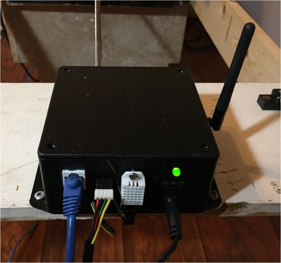
In the beginning, I connected the DHT sensor to Pro Mini A0 and separate power supply (5V) and ran DHT Example sketch and eading was "nan". Want to mention that all other wires (FAN setup ) attached to Pro Mini as well. Then I disconnect Pro Mini from setup and connect DHT to it (GND, VCC, and A0) got numbers by running DHT Example. Connect everything together (motor, display, radio) and connect DHT to Pro Mini (GND, VCC, and A0) turn on and got zeros for Temp and Hum. Got frustrated and left for a walk. When I come back, Temp: 85 and Hum 52. I was not patient enough. It takes 5 to 6 min for Temp to show on display. I also tried to connect DHT VCC to the external power supply 3.3 and 5 V, but leave GND connected to Pro Mini and it works.
-
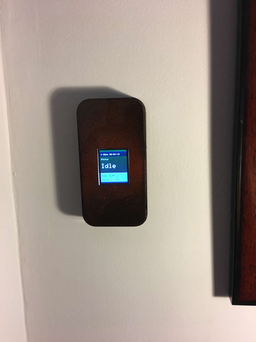
Display. I used old case from iPod. Sprayed a little red paint and top it with black. Push button at the bottom of the case.
-
I am using RCWL-0516 Microwave Radar Sensor for on/off the display. This sensor is very sensitive. I just want to activate the display in a close range. Any suggestions?
@lis610 said in 💬 Insulated Whole House Fan:
RCWL-0516
https://www.rogerclark.net/investigating-a-rcwl-9196-rcwl-0516-radar-motion-detector-modules/ shows some possible ways to read something other than a digital output of motion at 5 to 7 meters.
It doesn't look like there is a simple way to just make it less sensitive.
-
I am using RCWL-0516 Microwave Radar Sensor for on/off the display. This sensor is very sensitive. I just want to activate the display in a close range. Any suggestions?
@lis610 said in 💬 Insulated Whole House Fan:
I am using RCWL-0516 Microwave Radar Sensor for on/off the display. This sensor is very sensitive. I just want to activate the display in a close range. Any suggestions?
You could try the XYC-WB-DC radar sensor. This one allows the sensitivity to be adjusted by changing a resitor value. Here's a Youtube video about it:
https://www.youtube.com/watch?v=41rf6NbuhBs
I'm waiting for mine to come in from China, so no first hand experience yet on how these sensors work.
-
I am using RCWL-0516 Microwave Radar Sensor for on/off the display. This sensor is very sensitive. I just want to activate the display in a close range. Any suggestions?
@lis610 I have found with a 499K resistor the range is reduced to about 1.2m in a ABS box.
With a 1Mohm it was about 3m, I do not have many high value SMD resistors to experiment with but the lower the value the lower the range.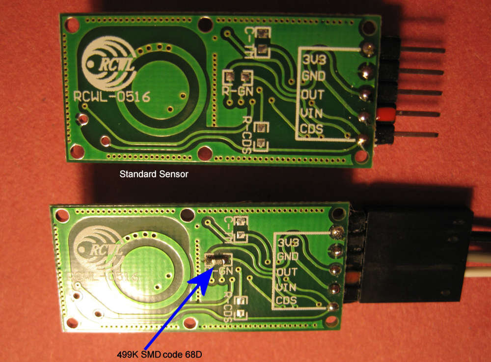
Just tried with a 333K and it operates about 0.8m in free air.